EP1453187A2 - Unité d'entrainement pour un véhicule électrique - Google Patents
Unité d'entrainement pour un véhicule électrique Download PDFInfo
- Publication number
- EP1453187A2 EP1453187A2 EP04004084A EP04004084A EP1453187A2 EP 1453187 A2 EP1453187 A2 EP 1453187A2 EP 04004084 A EP04004084 A EP 04004084A EP 04004084 A EP04004084 A EP 04004084A EP 1453187 A2 EP1453187 A2 EP 1453187A2
- Authority
- EP
- European Patent Office
- Prior art keywords
- motor
- refrigerant
- speed reducer
- inverter
- drive unit
- Prior art date
- Legal status (The legal status is an assumption and is not a legal conclusion. Google has not performed a legal analysis and makes no representation as to the accuracy of the status listed.)
- Granted
Links
Images




Classifications
-
- F—MECHANICAL ENGINEERING; LIGHTING; HEATING; WEAPONS; BLASTING
- F16—ENGINEERING ELEMENTS AND UNITS; GENERAL MEASURES FOR PRODUCING AND MAINTAINING EFFECTIVE FUNCTIONING OF MACHINES OR INSTALLATIONS; THERMAL INSULATION IN GENERAL
- F16H—GEARING
- F16H57/00—General details of gearing
- F16H57/04—Features relating to lubrication or cooling or heating
-
- B—PERFORMING OPERATIONS; TRANSPORTING
- B60—VEHICLES IN GENERAL
- B60L—PROPULSION OF ELECTRICALLY-PROPELLED VEHICLES; SUPPLYING ELECTRIC POWER FOR AUXILIARY EQUIPMENT OF ELECTRICALLY-PROPELLED VEHICLES; ELECTRODYNAMIC BRAKE SYSTEMS FOR VEHICLES IN GENERAL; MAGNETIC SUSPENSION OR LEVITATION FOR VEHICLES; MONITORING OPERATING VARIABLES OF ELECTRICALLY-PROPELLED VEHICLES; ELECTRIC SAFETY DEVICES FOR ELECTRICALLY-PROPELLED VEHICLES
- B60L1/00—Supplying electric power to auxiliary equipment of vehicles
- B60L1/02—Supplying electric power to auxiliary equipment of vehicles to electric heating circuits
-
- B—PERFORMING OPERATIONS; TRANSPORTING
- B60—VEHICLES IN GENERAL
- B60L—PROPULSION OF ELECTRICALLY-PROPELLED VEHICLES; SUPPLYING ELECTRIC POWER FOR AUXILIARY EQUIPMENT OF ELECTRICALLY-PROPELLED VEHICLES; ELECTRODYNAMIC BRAKE SYSTEMS FOR VEHICLES IN GENERAL; MAGNETIC SUSPENSION OR LEVITATION FOR VEHICLES; MONITORING OPERATING VARIABLES OF ELECTRICALLY-PROPELLED VEHICLES; ELECTRIC SAFETY DEVICES FOR ELECTRICALLY-PROPELLED VEHICLES
- B60L3/00—Electric devices on electrically-propelled vehicles for safety purposes; Monitoring operating variables, e.g. speed, deceleration or energy consumption
- B60L3/0023—Detecting, eliminating, remedying or compensating for drive train abnormalities, e.g. failures within the drive train
- B60L3/003—Detecting, eliminating, remedying or compensating for drive train abnormalities, e.g. failures within the drive train relating to inverters
-
- B—PERFORMING OPERATIONS; TRANSPORTING
- B60—VEHICLES IN GENERAL
- B60L—PROPULSION OF ELECTRICALLY-PROPELLED VEHICLES; SUPPLYING ELECTRIC POWER FOR AUXILIARY EQUIPMENT OF ELECTRICALLY-PROPELLED VEHICLES; ELECTRODYNAMIC BRAKE SYSTEMS FOR VEHICLES IN GENERAL; MAGNETIC SUSPENSION OR LEVITATION FOR VEHICLES; MONITORING OPERATING VARIABLES OF ELECTRICALLY-PROPELLED VEHICLES; ELECTRIC SAFETY DEVICES FOR ELECTRICALLY-PROPELLED VEHICLES
- B60L3/00—Electric devices on electrically-propelled vehicles for safety purposes; Monitoring operating variables, e.g. speed, deceleration or energy consumption
- B60L3/0023—Detecting, eliminating, remedying or compensating for drive train abnormalities, e.g. failures within the drive train
- B60L3/0061—Detecting, eliminating, remedying or compensating for drive train abnormalities, e.g. failures within the drive train relating to electrical machines
-
- B—PERFORMING OPERATIONS; TRANSPORTING
- B60—VEHICLES IN GENERAL
- B60L—PROPULSION OF ELECTRICALLY-PROPELLED VEHICLES; SUPPLYING ELECTRIC POWER FOR AUXILIARY EQUIPMENT OF ELECTRICALLY-PROPELLED VEHICLES; ELECTRODYNAMIC BRAKE SYSTEMS FOR VEHICLES IN GENERAL; MAGNETIC SUSPENSION OR LEVITATION FOR VEHICLES; MONITORING OPERATING VARIABLES OF ELECTRICALLY-PROPELLED VEHICLES; ELECTRIC SAFETY DEVICES FOR ELECTRICALLY-PROPELLED VEHICLES
- B60L50/00—Electric propulsion with power supplied within the vehicle
- B60L50/50—Electric propulsion with power supplied within the vehicle using propulsion power supplied by batteries or fuel cells
- B60L50/51—Electric propulsion with power supplied within the vehicle using propulsion power supplied by batteries or fuel cells characterised by AC-motors
-
- H—ELECTRICITY
- H02—GENERATION; CONVERSION OR DISTRIBUTION OF ELECTRIC POWER
- H02K—DYNAMO-ELECTRIC MACHINES
- H02K11/00—Structural association of dynamo-electric machines with electric components or with devices for shielding, monitoring or protection
- H02K11/30—Structural association with control circuits or drive circuits
- H02K11/33—Drive circuits, e.g. power electronics
-
- H—ELECTRICITY
- H02—GENERATION; CONVERSION OR DISTRIBUTION OF ELECTRIC POWER
- H02K—DYNAMO-ELECTRIC MACHINES
- H02K7/00—Arrangements for handling mechanical energy structurally associated with dynamo-electric machines, e.g. structural association with mechanical driving motors or auxiliary dynamo-electric machines
- H02K7/10—Structural association with clutches, brakes, gears, pulleys or mechanical starters
- H02K7/116—Structural association with clutches, brakes, gears, pulleys or mechanical starters with gears
-
- H—ELECTRICITY
- H02—GENERATION; CONVERSION OR DISTRIBUTION OF ELECTRIC POWER
- H02K—DYNAMO-ELECTRIC MACHINES
- H02K9/00—Arrangements for cooling or ventilating
- H02K9/19—Arrangements for cooling or ventilating for machines with closed casing and closed-circuit cooling using a liquid cooling medium, e.g. oil
- H02K9/197—Arrangements for cooling or ventilating for machines with closed casing and closed-circuit cooling using a liquid cooling medium, e.g. oil in which the rotor or stator space is fluid-tight, e.g. to provide for different cooling media for rotor and stator
-
- B—PERFORMING OPERATIONS; TRANSPORTING
- B60—VEHICLES IN GENERAL
- B60L—PROPULSION OF ELECTRICALLY-PROPELLED VEHICLES; SUPPLYING ELECTRIC POWER FOR AUXILIARY EQUIPMENT OF ELECTRICALLY-PROPELLED VEHICLES; ELECTRODYNAMIC BRAKE SYSTEMS FOR VEHICLES IN GENERAL; MAGNETIC SUSPENSION OR LEVITATION FOR VEHICLES; MONITORING OPERATING VARIABLES OF ELECTRICALLY-PROPELLED VEHICLES; ELECTRIC SAFETY DEVICES FOR ELECTRICALLY-PROPELLED VEHICLES
- B60L2210/00—Converter types
- B60L2210/40—DC to AC converters
-
- B—PERFORMING OPERATIONS; TRANSPORTING
- B60—VEHICLES IN GENERAL
- B60L—PROPULSION OF ELECTRICALLY-PROPELLED VEHICLES; SUPPLYING ELECTRIC POWER FOR AUXILIARY EQUIPMENT OF ELECTRICALLY-PROPELLED VEHICLES; ELECTRODYNAMIC BRAKE SYSTEMS FOR VEHICLES IN GENERAL; MAGNETIC SUSPENSION OR LEVITATION FOR VEHICLES; MONITORING OPERATING VARIABLES OF ELECTRICALLY-PROPELLED VEHICLES; ELECTRIC SAFETY DEVICES FOR ELECTRICALLY-PROPELLED VEHICLES
- B60L2240/00—Control parameters of input or output; Target parameters
- B60L2240/40—Drive Train control parameters
- B60L2240/42—Drive Train control parameters related to electric machines
- B60L2240/425—Temperature
-
- B—PERFORMING OPERATIONS; TRANSPORTING
- B60—VEHICLES IN GENERAL
- B60L—PROPULSION OF ELECTRICALLY-PROPELLED VEHICLES; SUPPLYING ELECTRIC POWER FOR AUXILIARY EQUIPMENT OF ELECTRICALLY-PROPELLED VEHICLES; ELECTRODYNAMIC BRAKE SYSTEMS FOR VEHICLES IN GENERAL; MAGNETIC SUSPENSION OR LEVITATION FOR VEHICLES; MONITORING OPERATING VARIABLES OF ELECTRICALLY-PROPELLED VEHICLES; ELECTRIC SAFETY DEVICES FOR ELECTRICALLY-PROPELLED VEHICLES
- B60L2240/00—Control parameters of input or output; Target parameters
- B60L2240/40—Drive Train control parameters
- B60L2240/52—Drive Train control parameters related to converters
- B60L2240/525—Temperature of converter or components thereof
-
- B—PERFORMING OPERATIONS; TRANSPORTING
- B60—VEHICLES IN GENERAL
- B60L—PROPULSION OF ELECTRICALLY-PROPELLED VEHICLES; SUPPLYING ELECTRIC POWER FOR AUXILIARY EQUIPMENT OF ELECTRICALLY-PROPELLED VEHICLES; ELECTRODYNAMIC BRAKE SYSTEMS FOR VEHICLES IN GENERAL; MAGNETIC SUSPENSION OR LEVITATION FOR VEHICLES; MONITORING OPERATING VARIABLES OF ELECTRICALLY-PROPELLED VEHICLES; ELECTRIC SAFETY DEVICES FOR ELECTRICALLY-PROPELLED VEHICLES
- B60L2270/00—Problem solutions or means not otherwise provided for
- B60L2270/10—Emission reduction
- B60L2270/14—Emission reduction of noise
- B60L2270/147—Emission reduction of noise electro magnetic [EMI]
-
- Y—GENERAL TAGGING OF NEW TECHNOLOGICAL DEVELOPMENTS; GENERAL TAGGING OF CROSS-SECTIONAL TECHNOLOGIES SPANNING OVER SEVERAL SECTIONS OF THE IPC; TECHNICAL SUBJECTS COVERED BY FORMER USPC CROSS-REFERENCE ART COLLECTIONS [XRACs] AND DIGESTS
- Y02—TECHNOLOGIES OR APPLICATIONS FOR MITIGATION OR ADAPTATION AGAINST CLIMATE CHANGE
- Y02T—CLIMATE CHANGE MITIGATION TECHNOLOGIES RELATED TO TRANSPORTATION
- Y02T10/00—Road transport of goods or passengers
- Y02T10/60—Other road transportation technologies with climate change mitigation effect
- Y02T10/64—Electric machine technologies in electromobility
-
- Y—GENERAL TAGGING OF NEW TECHNOLOGICAL DEVELOPMENTS; GENERAL TAGGING OF CROSS-SECTIONAL TECHNOLOGIES SPANNING OVER SEVERAL SECTIONS OF THE IPC; TECHNICAL SUBJECTS COVERED BY FORMER USPC CROSS-REFERENCE ART COLLECTIONS [XRACs] AND DIGESTS
- Y02—TECHNOLOGIES OR APPLICATIONS FOR MITIGATION OR ADAPTATION AGAINST CLIMATE CHANGE
- Y02T—CLIMATE CHANGE MITIGATION TECHNOLOGIES RELATED TO TRANSPORTATION
- Y02T10/00—Road transport of goods or passengers
- Y02T10/60—Other road transportation technologies with climate change mitigation effect
- Y02T10/70—Energy storage systems for electromobility, e.g. batteries
-
- Y—GENERAL TAGGING OF NEW TECHNOLOGICAL DEVELOPMENTS; GENERAL TAGGING OF CROSS-SECTIONAL TECHNOLOGIES SPANNING OVER SEVERAL SECTIONS OF THE IPC; TECHNICAL SUBJECTS COVERED BY FORMER USPC CROSS-REFERENCE ART COLLECTIONS [XRACs] AND DIGESTS
- Y02—TECHNOLOGIES OR APPLICATIONS FOR MITIGATION OR ADAPTATION AGAINST CLIMATE CHANGE
- Y02T—CLIMATE CHANGE MITIGATION TECHNOLOGIES RELATED TO TRANSPORTATION
- Y02T10/00—Road transport of goods or passengers
- Y02T10/60—Other road transportation technologies with climate change mitigation effect
- Y02T10/72—Electric energy management in electromobility
Definitions
- the present invention relates a drive unit for an electric vehicle which unit comprises a motor, an inverter and a speed reducer which are integrally supported by a structural member.
- Japanese Patent No. 3271416 discloses a drive unit for an electric vehicle, in which a motor and an inverter are coaxially and integrally arranged and are cooled by a cooling device built in the inverter using one kind of refrigerant.
- the cooling device of the inverter cools a surface of the motor which faces with the inverter, and therefore a cooling efficiency of the drive unit is not satisfactory.
- An aspect of the present invention resides in a drive unit which is for an electric vehicle and which comprises a motor; an inverter supplying alternating current electric power to the motor; a speed reducer reducing a revolution speed of a mechanical output of the motor; first refrigerant receiving heat of at least one of the motor and the inverter and outputting the heat into the atmosphere; second refrigerant receiving heat of at least one of the motor and the speed reducer and outputting the heat to the first refrigerant, a cooling performance of the first refrigerant being higher than a cooling performance of the second refrigerant; and a heat exchanger transferring the heat of the second refrigerant to the first refrigerant.
- the drive unit comprises a motor, an inverter, a speed reducer and a cooling system.
- the inverter is electrically connected to the motor, the inverter supplying alternating current electric power to the motor.
- the speed reducer is connected to the motor. The speed reducer reduces a revolution speed of a mechanical output of the motor.
- the cooling system comprises a first refrigerant passage in contact with at least one of the motor and the inverter, a second refrigerant passage in contact with at least one of the motor and the speed reducer, a heat exchanger connected to the first refrigerant passage and the second refrigerant passage, a radiating section connected to the first refrigerant passage and the heat exchanger and radiating heat into the atmosphere, first refrigerant circulating the first refrigerant passage, the heat exchanger and the radiating section, the first refrigerant receiving heat at the first refrigerant passage and the heat exchanger and radiating the heat at the radiating section, and second refrigerant circulating the second refrigerant passage and the heat exchanger, the second refrigerant receiving heat at the second refrigerant passage and radiating the heat at the heat exchanger.
- Fig. 1 is a cross sectional view showing a drive unit of a first embodiment according to the present invention.
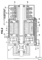
- Fig. 2 is a cross sectional view showing the drive unit of a second embodiment according to the present invention.
- Fig. 3 is a cross sectional view showing the drive unit of a third embodiment according to the present invention.
- Fig. 4 is a cross sectional view showing the drive unit of a fourth embodiment according to the present invention.
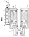
- Fig. 5 is a cross sectional view showing the drive unit of a fifth embodiment according to the present invention.
- Fig. 6 is a cross sectional view showing the drive unit of a sixth embodiment according to the present invention.
- Fig. 1 is a cross-sectional view of a drive unit of an electric vehicle according to a first embodiment of the present invention. Referring to Fig. 1, there is discussed the first embodiment of the drive unit.
- an inverter 50, a motor 60 and a differential speed reducer (speed reducer) 70 are aligned on an axis in the order of mentioned from a right hand side on Fig. 1.
- Inverter 50 supplies alternating-current electric power to motor 60 to drive motor 60.
- Differential speed reducer 70 reduces the speed of the mechanical output of motor 60 and distributes the mechanical output to left and right drive shafts 19 and 20.
- Stators 1 of motor 60 are fixed to a motor housing 8.
- Each stator 1 comprises a stator coil 1a and applies a torque to a rotor 2 according to the receipt of electric power to stator coils 2a.
- Rotor 2 is fixed to a motor shaft 3 of a cylindrical shape and transmits the torque to a sun gear 10.
- Both end portions of motor shaft 3 are supported by bearings 4 and 6. More specifically, bearing 4 is fixed to a left end bracket 5 constructing a left end wall of motor 60, and bearing 6 is fixed to a right end bracket 7 constructing a right end wall of motor 60.
- the arrangement of these bearing 4 and 6 function to equivalently maintain a clearance between stators 1 and rotor 2. This clearance is called an air gap and takes a value smaller than or equal to 1mm.
- the positions of bearings 4 and 6 are accurately maintained by positioning left and right end brackets 5 and 7 for respectively supporting bearings 4 and 6, with respect to an inner diameter of a motor housing 8 for fixing stator 1.
- Motor 60 is constructed by stator 1, rotor 2, motor shaft 3, bearings 4 and 6, eng brackets 5 and 7 and motor housing 8.
- differential speed reducer 70 which is disposed adjacent to motor 60.
- the drive unit of the first embodiment employs a planetary gear train type speed reducer as a speed reducer. That is, speed reducer 70 of the planetary gear train type comprises sun gear 10, planet gears 11, a planet carrier 13a, a ring gear 12 and a gear housing 23. By fixing ring gear 12 to gear housing 23, the motor speed inputted to sun gear 10 is reduced and outputted from planet carrier 13a.
- Planet carrier 13a is a part of a gear carrier 13 for a differential gear train which is constructed by four bevel gears 15, 16, 17 and 18. Bevel gears 15, 16, 17 and 18 are rotated according to the rotation of gear carrier 13.
- Gear carrier 13 is rotatably supported by gear housing 23 through a bearing 14.
- Bevel gear 15 of the differential gear train is integrally connected to a left drive shaft 19 extending in the leftward direction in Fig. 1.
- Bevel gear 17 is integrally connected to a right drive shaft 20 extending in the rightward direction in Fig. 1.
- the revolution speed of left drive shaft 19 is as same as that of right drive shaft 20
- four bevel gears 15 through 18 are integrally rotated with gear carrier 13 without generating relative revolutions thereamong.
- the differential gear train absorbs the difference by generating relative revolutions among bevel gears 15, 16, 17 and 18, and equivalently distributes torque to left and right drive shafts 19 and 20. That is, differential speed reducer 70 is constructed by a speed reducer of the planetary gear train type and a differential gear train.
- the speed reducer is constructed by a planetary gear train
- it may be constructed by a multiple planetary gear train type speed reducer or by a speed reducer constructed by spur gears.
- the differential gear train may be constructed by a planetary gear train type or other type.
- Right drive shaft 20 penetrates an inner space of motor shaft 3, a center hole of right end bracket 7, an inner space of a cylindrical portion 7a integral with right end bracket 7, and reaches a right end of the drive unit of the electric vehicle.
- a right end portion of right drive shaft 20 is supported by a bearing 24 attached to an end of cylindrical portion 7a.
- Right end bracket 7 is positioned with respect to the inner diameter of motor housing 8, and bearing 6 for supporting the end portion of motor shaft 3 is fixed to right end bracket 7. Therefore, right drive shaft 20 supported by bearing 24 is supported to maintain a coaxial relationship with motor shaft 3.
- Inverter 50 is adjacently disposed around an outer surface of cylindrical portion 7a which right drive shaft 20 penetrates.
- a protecting cover 26 of inverter 50 has a function of protecting the parts 25 of inverter 50 from stones bumped from a road surface and splashes, and a function of shielding electromagnetic noises produced by inverter 50.
- parts 25 of inverter 50 are attached to right end bracket 7 and cylindrical portion 7a as shown in Fig. 1 and integrally supported by right end bracket 7 and cylindrical portion 7a. Since parts 25 are not attached to protecting cover 26, protecting cover 26 may have a proper strength and is preferably made by an electro-conductive material so as to perform an electromagnetic shielding function. Accordingly, it is preferable that protecting cover 26 is made by resin and a metal plating film is attached on an inner surface of protecting cover 26 so as to perform an electromagnetic shielding effect.
- Protecting cover 26 may be produced by a thin metal sheet having a proper strength. By employing such a thin metal sheet, it also becomes possible to achieve the light weight of the drive unit of an electric vehicle and the electromagnetic shielding effect for inverter 50.
- a hole 7b is formed at an outer peripheral surface of right end bracket 7, and a connector 27 is attached to an outer end of hole 7b.
- Inverter 50 is electrically connected to an electric power source (such as a battery) through connecter 27 and a wire (not shown) penetrating hole 7b so that direct-current electric power necessary for generating a torque is supplied to parts 25 of inverter 50.
- a structural member 80 of the drive unit in the first embodiment comprises right end bracket 7 (including cylindrical portion 7a) which functions as a right end wall of motor 60 and surrounds right drive shaft 20 penetrating inverter 50, motor housing 8 which functions as an outer peripheral portion of motor 60, left end bracket 8 which functions as a left end wall of motor 60, and gear housing 23 which functions as an outer cover of differential speed reducer 70.
- This structural member 80 functions as a frame of the drive unit of the electric vehicle and integrally supports motor, 60, differential speed reducer 70 and inverter 50.
- cooling water antioxidant solution
- refrigerant cooling inverter 60 cooling water (antifreezing solution)
- a cooling performance includes a heat transfer characteristic.
- This cooling water is supplied to inverter 50 and heat exchanger 30 from a heat radiating section (radiator) 35 which is disposed outside of the drive unit and which radiates heat of cooling water into the atmosphere. More specifically, a cooling water inlet 31b is disposed at an outer periphery of right end bracket 7, a cooling water passage 7c is machined in right end bracket 7 and a cooling water passage 29 is disposed so as to directly cool heat generating portions of parts 25 of inverter 50, connected to cooling water passage 7c. Therefore, cooling water is supplied through cooling water inlet 31b to cooling water passage 7c and cooling water passage 29.
- Cooling water passing through cooling water passage 29 is fed to heat exchanger 30 integrally built in structural member 80 disposed under motor 60 and differential speed reducer 70. Cooling water fed to heat exchanger 30 absorbs heat of oil for cooling the motor 60 and differential speed reducer 70 and is then fed to heat radiating section 35 through a cooling water outlet 31a disposed at a cooling water output port. Cooling water is cooled by atmospheric air through heat radiating section 35. The circulation of cooling water is executed by a pump (not shown) disposed outside of the drive unit.
- differential speed reducer 70 is representatively explained through the explanation of cooling the gears of differential speed reducer 70.
- the cooling operation of motor 60 is representatively explained through the explanations of cooling the stator coils 1a which are the representative heat generating portions and of cooling the motor shaft 3 and bearings 4 and 6.
- the cooling of motor 60 means cooling of stator coils 1a, motor shaft 3 and bearings 4 and 6.
- Stator coils 1a which are main heat generating portions of motor 60, are cooled by oil.
- Oil cooling passages 34 are provided in slots of motor 60 as shown in Fig. 1.
- oil pump 32 By flowing oil through oil passages 34 by means of oil pump 32, the heat generated by stator coils 1a is transferred to oil.
- oil cooling passage 28 of heat exchanger 30 By the circulation of oil through an oil cooling passage 28 of heat exchanger 30, the heat transferred from stator coils 1a to oil is transferred into cooling water employed for cooling the inverter 50.
- differential speed reducer 70 motor shaft 3 and motor bearings 4 and 6.
- Lubrication and cooling of differential speed reducer 70, motor shaft 3 and motor bearings 4 and 6 are normally executed using oil.
- Oil is supplied to bevel gears 15 through 18 of the differential gear train, sun gear 10, planet gears 11 and ring gear 12 of the planetary gear train type speed reducer, motor shaft 3 and bearings 4 and 6 supporting motor shaft 3 to execute the lubrication and cooling of these elements.
- motor shaft 3 is not shown in Figures, this cooling is generally arranged to cool magnets embedded in rotor 2 and may be omitted herein.
- Oil circulated by oil pump 3 receives heat of the gears of differential speed reducer 70, motor shaft 3 and bearings 4 and 6 of motor shaft 3, and discharges the heat into cooling water by flowing oil through oil cooling passage 28 of heat exchange 30.
- Motor 60 and differential speed reducer 70 are cooled by oil.
- Oil for cooling the stator coils 1a may be commonly used with oil for cooling the differential speed reducer 70, motor shaft 3 and bearings 4 and 6 of motor shaft 3.
- a mechanical pump utilizing a rotational force of motor shaft 3 may be employed as an oil pump.
- heat exchanger 30 integrally built in structural member 80 can transfer the heat absorbed by oil into cooling water, it becomes possible to simplify a heat radiating line outside of the drive unit into one line. This enables heat radiating section 35 to be downsized and improves the easiness of mounting the drive unit on an electric vehicle.
- heat exchanger 30 is integrally assembled with structural member 80 at a lower portion of the drive unit, it becomes possible to effectively utilize a conventional wasted space of the drive unit, and therefore it is possible to downsize the drive unit totally. Further, since it is possible to dispose heat exchanger 30 in an oil pan set at a lowermost portion of the drive unit of the electric vehicle, heat exchanger 30 can effectively perform as an oil sump and heat exchanger.
- a cooling system is arranged such that cooling water cools stator coils 1a of motor 60 in addition to inverter 50.
- cooling water inlet 31b and motor cooling-water passages 8a are provided in motor housing 8.
- cooling water flows from cooling water inlet 31b through motor cooling water passages 8a, cooling water passage 29 and a cooling water passage 30a of heat exchanger 30 to cooling water output 31a in order of mention.
- Cooling water passage 29 may be extended toward motor 30.
- the cooling system may be arranged such that cooling water is first supplied to cooling water passage 29. Since stator coils 1a of motor 60 generate a large quantity of heat, by first flowing cooling water through cooling water passages 8a for motor 60, the cooling water effectively absorbs the heat generated by motor 60.
- the second embodiment has been shown and described such that cooling water passages are formed in motor housing 8, the cooling of motor 60 may be executed by providing passages in the slots as shown in Fig. 1 and flowing cooling water through the passages.
- oil lubricates and cools the gears of differential speed reducer 70, motor shaft 3, bearings 4 and 6 of motor shaft 3.
- Oil is fed to oil cooling passage 28 of heat exchanger 30 built in structural member 80 disposed at a lower portion of motor 30 and differential speed reducer 70 by means of oil pump 32, and radiates the heat into cooling water.
- the cooling water absorbs the heat from oil in heat exchanger 30 and is fed to heat radiating section 35 through cooling water outlet 31a to radiate the heat of the cooling water into the atmosphere.
- the second embodiment according to the present invention is arranged such that differential speed reducer 70, motor shaft 3 and bearings 4 and 6 of motor 60 are cooled by common oil and the heat of the oil is transferred to the cooling water for cooling inverter 50 and stator coils 1a of motor 60, the temperature of oil for cooling motor shaft 3 and bearings 4 and 6 is lowered. Accordingly, it becomes possible to combine the heat radiating lines into one line while improving the durability of parts. This enables heat radiating section (radiator) 35 to be downsized, and improves the mounting capability of the drive unit on the electric vehicle.
- the second embodiment is arranged such that stator coils 1a, which generates large quantities of heat, are cooled by cooling water, and that motor shaft 3, bearings 4 and 6 of motor shaft 3, which generate relatively small quantities of heat, are cooled by oil. Accordingly, it becomes possible to minimize the side of heat exchanger 30 integrally built in structural member 80.
- FIG. 3 there is discussed a third embodiment of the drive unit for the electric vehicle in accordance with the present invention.
- This third embodiment is specifically arranged such that heat exchanger 30 is disposed at four corners of a rectangle circumscribed about an outer peripheral circle of motor 60 as shown in Fig. 3, in contrast to the arrangement of the first and second embodiments wherein heat exchanger 30 is built in structural member 80 of a cylindrical shape.
- This arrangement of heat exchanger 30 at the four corners enables the effective utilization of an wasted space, and enables the downsizing of the drive unit.
- heat exchanger 30 at the four corners may be modified according to the desired performance of heat exchanger 30.
- heat exchanger 30 may be disposed at two or one corner of the rectangle.
- a fourth embodiment of the drive unit for the electric vehicle in accordance with the present invention.
- This forth embodiment is specifically arranged such that motor 60 and differential speed reducer (speed reducer) 70 are aligned on an axis and that parts 25 of inverter 50 are received in an inverter housing 51 which is attached on motor 60. More specifically, inverter 50 is disposed in parallel with motor 60.
- This arrangement also enables heat radiating section (radiator) 35 to be downsized, and improves the mounting capability of the drive unit on the electric vehicle.
- the fourth embodiment is further arranged such that structural member 81 comprises right end bracket 7 functioning as a right end wall of motor 60, motor housing 8 functioning as an outer peripheral portion of motor 60, left end bracket 6 functioning as a left end wall of motor 60, gear housing 23 functioning as an outer shell of differential speed reducer 70, and an inverter housing 51 surrounding inverter 50.
- This structural member 81 functions as a frame of the drive unit of the electric vehicle, and integrally supports motor 60, differential speed reducer 70 and inverter 50.
- inverter 50 and stator coils 1a of motor 60 are cooled by cooling water, and a flow pass of the cooling water is represented by arrows in Fig. 4. More specifically, the cooling water is fed from cooling water inlet 31 formed at inverter housing 51 through cooling water passage 29 for cooling inverter 50 to a passage in motor housing 8 for cooling the stator coils 1a of motor 60. Thereafter, cooling water cools oil which has received the heat of the gears of differential speed reducer 70, motor shaft 3 and bearings 4 and 6 of motor shaft 3 at heat exchanger 30. More specifically, heat of oil flowing through oil cooling passage 28 is transferred to cooling water flowing through cooling water passage in heat exchanger 30. Thereafter, the cooling water received the heat is supplied to heat radiating section 35 through cooling water outlet 31a and radiates the heat into the atmosphere through heat radiating section 35.
- the fourth embodiment according to the present also posses the advantages gained by the second embodiment.
- FIG. 5 there is shown a fifth embodiment of the drive unit of the electric vehicle in accordance with the present invention.
- the fifth embodiment is arranged such that motor 60 and differential speed reducer (speed reducer) 70 are adjacently aligned on an axis.
- Parts 24 of inverter 50 are received in inverter housing 51.
- Heat exchanger 30 is attached to a side wall of inverter housing 51 and is integrally built in structural member 81 so that inverter housing 51 is disposed in parallel with motor 60.
- cooling water cools inverter 50 and oil flowing through heat exchanger 30.
- Stator coil 1a which main generates heat in motor 60, is cooled by oil.
- oil passage 34 is provided at slots of motor 60, and oil circulated by oil pump 32 is fed to oil passage 34. By this oil flowing, the heat generated by stator coils 1a is transferred to oil flowing through oil passage 34. Further, the heat transferred to oil is transferred to cooling water in heat exchanger 30.
- Motor 60 and differential speed reducer 70 are cooled by oil through oil passage 34 at slots of motor 60.
- the oil flowing through heat exchanger 30 is commonly used with oil for cooling and lubricating the gears of differential speed reducer 70, motor shaft 3 and bearings 4 and 6 of motor shaft 3 and is circulated by oil pump 32.
- the heat transferred to oil from motor 60 and differential speed reducer 70 is radiated into cooling water through heat exchanger 30.
- cooling water is supplied from cooling water inlet 31b provided at inverter housing 51 and flows through cooling water passage 29 to cool parts 25 of inverter 50. Further, cooling water receives the heat from oil in heat exchanger 30 installed at a side portion of inverter housing 51, and radiates the received heat at heat radiating section 35 into the atmosphere by being fed to heat radiating section 35 through cooling water outlet 31a.
- the fifth embodiment according to the present also posses the advantages gained by the second embodiment.
- FIG. 6 there is discussed a sixth embodiment of the drive unit of the electric vehicle in accordance with the present invention.
- heat exchanger 30 is disposed between inverter 50 and motor 60.
- inverter 50, heat exchanger 30, motor 60 and differential speed reducer 70 are adjacently aligned on an axis, and are integrally supported by structural member 82.
- Structural member 82 comprises right end bracket 7 (including a cylindrical portion 7a) which functions as a right end wall of motor 60 and surrounds right drive shaft 30 penetrating inverter 50, motor housing 8 which functions as an outer peripheral portion of motor 60, left end bracket 5 which functions as a left end wall of motor 60, and a heat exchanger housing 33 which is a shell of heat exchanger 30.
- This structural member 82 functions as a frame of the drive unit and integrally supports motor 60, differential speed reducer 70, inverter 50 and heat exchanger 30 as an integral structure.
- heat exchanger 30 having a relatively heavy weight is employed as a structural member, it becomes possible to reduce a total weight of the drive unit.
- This arrangement eliminates the need for a new structural member for heat exchanger 30.
- cooling water is entered in the drive unit from cooling water inlet 31b and flows through a passage formed in heat exchanger housing 33 and cooling water passage 29 to cool inverter 50. Then, cooling water receives heat from oil cooling passage 28 at heat exchanger 30 and flows out from cooling water outlet 31a. Thereafter, the flowed-out cooling water is fed to heat radiating section 35 provided outside of the drive unit to radiate the heat of cooling water into the atmosphere.
- motor 60 and differential speed reducer 70 are cooled by oil, and oil for cooling stator coils 1a is commonly used with oil for cooling and lubricating a mechanical system including gears of differential speed reducer (speed reducer) 70, motor shaft 3 and bearings 4 and 6 of motor shaft 3.
- Oil pump 32 collects oil for cooling and lubricating a mechanical system including the gears of differential speed reducer 70, motor shaft 3 and bearings 4 and 6 of motor shaft 3, and fed the oil to oil passages 34 in the slots so that the oil is cooled by cooling water in heat exchanger 30.
- heat exchanger 30 integrally assembled with structural member of the drive unit is disposed at a lower portion of motor 60, aligned with motor 60, disposed at four corners of the rectangle circumscribed with an outer peripheral circle of motor 60 or at one of the four corners
- the arrangement of heat exchanger 30 is not limited to these arrangements and may employ the combination of these discussed arrangements.
- the size of heat exchanger 30 is basically determined according to the generated heat quantity of inverter 50, motor 60 and differential speed reducer 70 although it is varied according to the performance thereof.
Landscapes
- Engineering & Computer Science (AREA)
- Power Engineering (AREA)
- Mechanical Engineering (AREA)
- Transportation (AREA)
- Life Sciences & Earth Sciences (AREA)
- Sustainable Development (AREA)
- Sustainable Energy (AREA)
- General Engineering & Computer Science (AREA)
- Microelectronics & Electronic Packaging (AREA)
- Motor Or Generator Cooling System (AREA)
- Electric Propulsion And Braking For Vehicles (AREA)
- General Details Of Gearings (AREA)
- Arrangement Or Mounting Of Propulsion Units For Vehicles (AREA)
Applications Claiming Priority (2)
| Application Number | Priority Date | Filing Date | Title |
|---|---|---|---|
| JP2003047083A JP3794392B2 (ja) | 2003-02-25 | 2003-02-25 | 電気自動車の駆動ユニット |
| JP2003047083 | 2003-02-25 |
Publications (3)
| Publication Number | Publication Date |
|---|---|
| EP1453187A2 true EP1453187A2 (fr) | 2004-09-01 |
| EP1453187A3 EP1453187A3 (fr) | 2005-05-25 |
| EP1453187B1 EP1453187B1 (fr) | 2009-09-16 |
Family
ID=32767709
Family Applications (1)
| Application Number | Title | Priority Date | Filing Date |
|---|---|---|---|
| EP04004084A Expired - Lifetime EP1453187B1 (fr) | 2003-02-25 | 2004-02-23 | Unité d'entrainement pour un véhicule électrique |
Country Status (4)
| Country | Link |
|---|---|
| US (1) | US7775060B2 (fr) |
| EP (1) | EP1453187B1 (fr) |
| JP (1) | JP3794392B2 (fr) |
| DE (1) | DE602004023147D1 (fr) |
Cited By (12)
| Publication number | Priority date | Publication date | Assignee | Title |
|---|---|---|---|---|
| WO2018229507A1 (fr) * | 2017-06-15 | 2018-12-20 | Avid Technology Limited | Groupe motopropulseur électrique intégré |
| CN109075664A (zh) * | 2016-04-12 | 2018-12-21 | 戴姆勒股份公司 | 用于汽车动力传动系的混合动力模块 |
| DE102018209340B3 (de) | 2018-06-12 | 2019-04-25 | Bayerische Motoren Werke Aktiengesellschaft | Betriebsstrategie für einen Mehrphasensystem-Inverter einer elektrischen Antriebseinheit für ein Kraftfahrzeug |
| FR3086123A1 (fr) * | 2018-09-14 | 2020-03-20 | Valeo Equipements Electriques Moteur | Machine electrique tournante munie d'un module electronique de puissance integre a un carter d'un element reducteur |
| CN111211644A (zh) * | 2020-03-19 | 2020-05-29 | 温州市塔星电子科技有限公司 | 一种自动自我保护电机 |
| WO2021047718A1 (fr) * | 2019-09-10 | 2021-03-18 | Schaeffler Technologies AG & Co. KG | Dispositif d'entraînement électrique refroidissable et système d'entraînement |
| CN112821676A (zh) * | 2019-10-31 | 2021-05-18 | 布鲁萨电子公司 | 带有电动机的紧凑动力总成 |
| GB2605011A (en) * | 2019-05-31 | 2022-09-21 | Magnix Usa Inc | High-torque electric motor assembly |
| US12191722B2 (en) | 2019-05-31 | 2025-01-07 | MagniX USA, Inc. | High-torque electric motor assembly |
| FR3159068A1 (fr) * | 2024-02-07 | 2025-08-08 | Poclain Hydraulics Industrie | Ensemble pour moteur-roue |
| FR3158921A1 (fr) * | 2024-02-07 | 2025-08-08 | Poclain Hydraulics Industrie | Ensemble pour moteur-roue |
| EP4576519A4 (fr) * | 2022-11-16 | 2025-12-17 | Aisin Corp | Système de refroidissement |
Families Citing this family (81)
| Publication number | Priority date | Publication date | Assignee | Title |
|---|---|---|---|---|
| JP2004187437A (ja) * | 2002-12-05 | 2004-07-02 | Nissan Motor Co Ltd | モータ駆動ユニット |
| JP4501667B2 (ja) * | 2004-12-14 | 2010-07-14 | 三菱電機株式会社 | 車両駆動装置 |
| US7210304B2 (en) * | 2005-02-09 | 2007-05-01 | General Motors Corporation | Cooling arrangements for integrated electric motor-inverters |
| ITTO20050361A1 (it) * | 2005-05-27 | 2006-11-28 | Itw Ind Components Srl | Dispositivo e metodo di controllo della temperatura interna di una cella frigorifera in un frigorifero-congelatore di tipo combinato |
| JP2007218407A (ja) * | 2006-02-20 | 2007-08-30 | Ntn Corp | 自動車駆動ユニット |
| JP4069950B2 (ja) * | 2006-09-20 | 2008-04-02 | トヨタ自動車株式会社 | 車両の駆動装置及び車両 |
| JP2008215236A (ja) * | 2007-03-06 | 2008-09-18 | Mitsubishi Heavy Ind Ltd | 車載用電動圧縮機 |
| JP5013198B2 (ja) * | 2007-11-26 | 2012-08-29 | マツダ株式会社 | 車両の駆動装置 |
| JP5158418B2 (ja) * | 2008-01-17 | 2013-03-06 | マツダ株式会社 | 車両用駆動装置 |
| DE102008049238A1 (de) * | 2008-05-30 | 2009-12-03 | Wabco Gmbh | Vorrichtung zum Betreiben eines Hilfsaggregates eines Fahrzeuges, insbesondere Nutzfahrzeuges |
| CA2734784C (fr) * | 2008-08-22 | 2015-04-14 | Flsmidth A/S | Dispositif d'entrainement pour charges importantes et broyeur entraine par ce dispositif |
| JP5625565B2 (ja) * | 2010-07-13 | 2014-11-19 | 株式会社Ihi | 回転機及び車両 |
| US9118229B2 (en) | 2010-07-26 | 2015-08-25 | Nissan Motor Co., Ltd. | Electric drive unit |
| US20120112568A1 (en) * | 2010-11-04 | 2012-05-10 | Remy Technologies, L.L.C. | Cooling system for an electric machine system including an alternating current (ac) electric machine having an integrated switch assembly |
| JP2013038840A (ja) * | 2011-08-04 | 2013-02-21 | Nissan Motor Co Ltd | 永久磁石型電動モータの冷却構造 |
| JP5811335B2 (ja) * | 2011-09-08 | 2015-11-11 | 株式会社ジェイテクト | 軸受装置、これを備えた減速機構、及びモータ回転力伝達装置 |
| WO2013069128A1 (fr) * | 2011-11-10 | 2013-05-16 | 株式会社安川電機 | Machine électrique tournante |
| JP2013158161A (ja) * | 2012-01-31 | 2013-08-15 | Fuji Electric Co Ltd | 回転電機 |
| JP6194005B2 (ja) * | 2013-10-02 | 2017-09-06 | 川崎重工業株式会社 | 電動車両 |
| DE102014215758A1 (de) * | 2014-08-08 | 2016-02-11 | Siemens Aktiengesellschaft | Elektrische Maschine mit einem ersten Kreislauf und einem zweiten Kreislauf |
| JP6319049B2 (ja) * | 2014-10-31 | 2018-05-09 | 株式会社安川電機 | 駆動装置及びそれを備える乗り物 |
| KR101697592B1 (ko) * | 2014-12-16 | 2017-02-01 | 엘지전자 주식회사 | 회전전기기계 |
| KR101679761B1 (ko) | 2015-04-07 | 2016-11-28 | 주식회사 브이씨텍 | 냉각 구조 공유형 일체형 전기 동력 시스템 |
| US10644571B2 (en) * | 2015-09-29 | 2020-05-05 | Faraday & Future Inc. | Integrated drive and motor assemblies |
| JP2017145874A (ja) * | 2016-02-17 | 2017-08-24 | Ntn株式会社 | 車両駆動装置 |
| DE112017003994T5 (de) * | 2016-08-09 | 2019-04-18 | Nidec Corporation | Motoreinheit |
| WO2018030218A1 (fr) * | 2016-08-09 | 2018-02-15 | 日本電産株式会社 | Moteur |
| CN106505782B (zh) * | 2016-11-30 | 2019-02-01 | 浙江辰珂西传动机械有限公司 | 一种用于减速电机的散热保护罩 |
| US11011955B2 (en) | 2017-03-28 | 2021-05-18 | Lg Electronics Inc. | Motor |
| KR102177016B1 (ko) * | 2017-03-28 | 2020-11-10 | 엘지전자 주식회사 | 모터 |
| KR101927625B1 (ko) * | 2017-06-27 | 2019-03-07 | 현대위아 주식회사 | 감속기 및 인버터가 일체로 구비된 모터 |
| JP6628779B2 (ja) * | 2017-10-25 | 2020-01-15 | 本田技研工業株式会社 | 機電一体型回転電機装置 |
| US11515758B2 (en) * | 2017-12-28 | 2022-11-29 | Nidec Corporation | Motor unit |
| CN108258838A (zh) * | 2018-03-22 | 2018-07-06 | 合肥巨动力系统有限公司 | 一种电机系统一体化结构 |
| CN108691762B (zh) * | 2018-03-30 | 2022-12-06 | 中国北方车辆研究所 | 一种用于油泵的散热装置 |
| CN111869058B (zh) * | 2018-03-30 | 2023-06-09 | 本田技研工业株式会社 | 旋转电机的冷却结构 |
| US11685252B2 (en) * | 2018-04-11 | 2023-06-27 | Texa Dynamics S.R.L. | Suspension and traction system for vehicles |
| JP7006486B2 (ja) * | 2018-04-25 | 2022-01-24 | 株式会社アイシン | 車両用駆動装置 |
| KR102018231B1 (ko) * | 2018-07-11 | 2019-09-04 | 엘지전자 주식회사 | 전동기 |
| KR102076755B1 (ko) * | 2018-09-20 | 2020-02-12 | 엘지전자 주식회사 | 전동기 |
| DE102018131638B4 (de) * | 2018-12-10 | 2025-10-02 | Zollern Gmbh & Co. Kg | Motor-Getriebe-Einheit, insbesondere für eine Tunnelbohrmaschine oder zum Antrieb eines Zahnkranzes |
| US11125108B2 (en) * | 2018-12-17 | 2021-09-21 | Borgwarner Inc. | Liquid-cooled enclosure for turbocharger power module |
| DE102018222513A1 (de) * | 2018-12-20 | 2020-06-25 | Zf Friedrichshafen Ag | Getriebevorrichtung für einen Multicopter |
| JP7201710B2 (ja) * | 2018-12-28 | 2023-01-10 | 日立Astemo株式会社 | 演算装置 |
| DE112020001073T5 (de) * | 2019-03-06 | 2021-12-23 | Nidec Corporation | Motoreinheit |
| EP3944471A4 (fr) * | 2019-03-20 | 2022-11-02 | LG Magna e-Powertrain Co., Ltd. | Module de génération d'énergie intelligent |
| PE20212032A1 (es) | 2019-03-29 | 2021-10-20 | Tae Tech Inc | Sistemas de energia basados en modulos que pueden presentar configuraciones en cascada e interconectadas y metodos relacionados con los mismos |
| JP7318287B2 (ja) * | 2019-04-11 | 2023-08-01 | ニデック株式会社 | 駆動装置 |
| JP7278845B2 (ja) * | 2019-04-11 | 2023-05-22 | ニデック株式会社 | 駆動装置 |
| KR102710615B1 (ko) | 2019-04-25 | 2024-09-27 | 아메리칸 액슬 앤드 매뉴팩쳐링, 인코포레이티드 | 전기 구동 모듈 |
| DE102020207841B4 (de) * | 2019-06-28 | 2023-11-30 | Nidec Corporation | Motoreinheit |
| CN114556752B (zh) * | 2019-11-02 | 2024-07-12 | 博格华纳公司 | 具有提高效率的驱动模块 |
| KR102696291B1 (ko) | 2019-12-24 | 2024-08-20 | 엘지마그나 이파워트레인 주식회사 | 회전전기기계 |
| JP6828837B1 (ja) * | 2020-01-16 | 2021-02-10 | 株式会社明電舎 | 回転機システム |
| JP7419620B2 (ja) * | 2020-02-06 | 2024-01-23 | ジヤトコ株式会社 | 動力伝達装置 |
| US12005771B2 (en) * | 2020-05-20 | 2024-06-11 | Deere & Company | Lightweight high-efficiency, high temperature electric drive system |
| WO2021237539A1 (fr) * | 2020-05-27 | 2021-12-02 | 华为数字能源技术有限公司 | Groupe motopropulseur et véhicule électrique |
| US11827085B2 (en) * | 2020-08-12 | 2023-11-28 | Schaeffler Technologies AG & Co. KG | Electric transmission assembly including hydrodynamic bearing |
| EP3988261B1 (fr) * | 2020-10-26 | 2023-02-01 | Siemens Aktiengesellschaft | Articulation pour un robot |
| WO2022098636A1 (fr) | 2020-11-03 | 2022-05-12 | H3X Technologies Inc. | Moteur électrique à onduleur intégré et système de refroidissement partagé |
| JP7647276B2 (ja) * | 2020-11-19 | 2025-03-18 | ニデック株式会社 | 駆動装置、及び車両 |
| US11876433B2 (en) * | 2020-11-19 | 2024-01-16 | Nidec Corporation | Drive device |
| JP7733984B2 (ja) * | 2021-03-08 | 2025-09-04 | ニデック株式会社 | 駆動装置 |
| EP4307537A4 (fr) * | 2021-03-09 | 2024-09-18 | Jatco Ltd. | Composant |
| KR20250143856A (ko) | 2021-03-15 | 2025-10-02 | 아메리칸 액슬 앤드 매뉴팩쳐링, 인코포레이티드 | 전기 구동 유닛 |
| JP7631968B2 (ja) * | 2021-03-25 | 2025-02-19 | ニデック株式会社 | 駆動装置、及び車両 |
| JP7547023B2 (ja) * | 2021-06-24 | 2024-09-09 | ジヤトコ株式会社 | 車両 |
| WO2022270217A1 (fr) * | 2021-06-24 | 2022-12-29 | ジヤトコ株式会社 | Unité |
| EP4362298A4 (fr) * | 2021-06-24 | 2024-09-25 | Jatco Ltd. | Unité |
| JP7399603B2 (ja) | 2021-06-24 | 2023-12-18 | ジヤトコ株式会社 | ユニット |
| US20240227548A1 (en) * | 2021-06-24 | 2024-07-11 | Jatco Ltd | Unit |
| EP4361468A4 (fr) * | 2021-06-24 | 2024-10-02 | Jatco Ltd. | Système |
| JP2023042978A (ja) * | 2021-09-15 | 2023-03-28 | 日本電産株式会社 | 駆動装置 |
| US12009723B2 (en) * | 2021-09-21 | 2024-06-11 | Dana Automotive Systems Group, Llc | Electric motor with water jacket and oil-cooled stator and method for operation of the electric motor |
| CN118633229A (zh) | 2021-12-01 | 2024-09-10 | 美国轮轴制造公司 | 具有与通过壳体总成传递的梁载荷隔离的电机总成的电驱动单元 |
| WO2023127409A1 (fr) * | 2021-12-28 | 2023-07-06 | ニデック株式会社 | Dispositif d'entraînement |
| DE102022108456A1 (de) * | 2022-04-07 | 2023-10-12 | Schaeffler Technologies AG & Co. KG | Kühlungseinrichtung und Antriebsanordnung |
| JP7784073B2 (ja) * | 2022-09-06 | 2025-12-11 | 日産自動車株式会社 | 減速機構付きモータ |
| DE102022004132A1 (de) * | 2022-11-07 | 2024-05-08 | Mercedes-Benz Group AG | Elektrische Antriebsvorrichtung für ein elektrifiziertes Kraftfahrzeug |
| JP2024081490A (ja) * | 2022-12-06 | 2024-06-18 | トヨタ自動車株式会社 | 駆動装置 |
| WO2026023019A1 (fr) * | 2024-07-25 | 2026-01-29 | 日産自動車株式会社 | Dispositif d'entraînement |
Family Cites Families (28)
| Publication number | Priority date | Publication date | Assignee | Title |
|---|---|---|---|---|
| US3548612A (en) * | 1969-01-27 | 1970-12-22 | Tokyo Shibaura Electric Co | Refrigerating compressor with oil cooler |
| US3721108A (en) * | 1971-06-15 | 1973-03-20 | Vilter Manufacturing Corp | Refrigerant cooled compressor |
| US3830289A (en) * | 1972-05-18 | 1974-08-20 | D Olson | Oil cooler |
| GB1448824A (en) * | 1972-11-18 | 1976-09-08 | Lucas Industries Ltd | Dynamo electric machines |
| US4125345A (en) * | 1974-09-20 | 1978-11-14 | Hitachi, Ltd. | Turbo-fluid device |
| JPS569636A (en) * | 1979-07-02 | 1981-01-31 | Nissan Motor Co Ltd | Temperature controller for internal combustion engine |
| US4576555A (en) * | 1984-11-13 | 1986-03-18 | Tecumseh Products Company | Oil dispersing device |
| EP0364965B1 (fr) * | 1988-10-18 | 1993-08-18 | Nissan Motor Co., Ltd. | Suspension active de véhicule automobile avec commande en fonction de l'angle de dérive pour améliorer la réponse de la direction |
| DE4139997A1 (de) * | 1990-12-06 | 1992-07-09 | Ozcan Akdogan | Schaltungsanordnung mit leistungs-mosfet-transistoren |
| US5217085A (en) * | 1992-05-04 | 1993-06-08 | Ford Motor Company | Lubrication and cooling system for a powertrain including an electric motor |
| US5255733A (en) * | 1992-08-10 | 1993-10-26 | Ford Motor Company | Hybird vehicle cooling system |
| ATE157822T1 (de) * | 1993-12-23 | 1997-09-15 | Abb Daimler Benz Transp | Kühlsystem für einen motor |
| JP3271416B2 (ja) | 1994-02-18 | 2002-04-02 | 株式会社デンソー | 電力変換器及びそれを用いた電動車両の駆動装置 |
| JP3508206B2 (ja) * | 1994-04-27 | 2004-03-22 | 株式会社デンソー | 車両駆動用電動機 |
| JP3451141B2 (ja) * | 1994-11-14 | 2003-09-29 | 本田技研工業株式会社 | バッテリ温度調節装置 |
| DE19509788A1 (de) * | 1995-03-17 | 1996-09-19 | Behr Gmbh & Co | Doppelrohrwärmetauscher und Verfahren zu seiner Herstellung |
| DE19704408A1 (de) * | 1997-02-06 | 1998-08-13 | Baumueller Anlagen Systemtech | Wärmerückgewinnungsverfahren sowie dessen Verwendung |
| DE19714784A1 (de) * | 1997-04-10 | 1998-10-22 | Danfoss As | Kompaktantrieb |
| US6263960B1 (en) * | 1997-11-28 | 2001-07-24 | Denso Corporation | Oil cooler with cooling water side fin and oil side fin |
| JP3891533B2 (ja) * | 1998-11-16 | 2007-03-14 | アイシン・エィ・ダブリュ株式会社 | 駆動装置 |
| JP3886696B2 (ja) * | 1999-04-27 | 2007-02-28 | アイシン・エィ・ダブリュ株式会社 | 駆動装置 |
| JP3886697B2 (ja) * | 1999-04-27 | 2007-02-28 | アイシン・エィ・ダブリュ株式会社 | 駆動装置 |
| DE10022319A1 (de) * | 2000-05-09 | 2001-11-29 | Voith Turbo Kg | Antriebseinheit, insbesondere elektrische Antriebseinheit zum Antrieb einer Radachse in Transaxelbauweise |
| JP3972170B2 (ja) * | 2000-09-26 | 2007-09-05 | スズキ株式会社 | 車両用モータアシスト装置の冷却構造 |
| JP3910384B2 (ja) * | 2000-10-13 | 2007-04-25 | 本田技研工業株式会社 | 車両用バッテリ冷却装置 |
| JP2002168591A (ja) * | 2000-11-29 | 2002-06-14 | Denso Corp | アルミニウム製熱交換器 |
| JP3835202B2 (ja) * | 2001-05-18 | 2006-10-18 | トヨタ自動車株式会社 | 車両用駆動制御装置 |
| US20040045749A1 (en) * | 2002-09-06 | 2004-03-11 | Ford Global Technologies, Inc. | Cooling system and method for a hybrid electric vehicle |
-
2003
- 2003-02-25 JP JP2003047083A patent/JP3794392B2/ja not_active Expired - Lifetime
-
2004
- 2004-02-23 EP EP04004084A patent/EP1453187B1/fr not_active Expired - Lifetime
- 2004-02-23 DE DE602004023147T patent/DE602004023147D1/de not_active Expired - Lifetime
- 2004-02-25 US US10/785,197 patent/US7775060B2/en not_active Expired - Fee Related
Cited By (20)
| Publication number | Priority date | Publication date | Assignee | Title |
|---|---|---|---|---|
| CN109075664A (zh) * | 2016-04-12 | 2018-12-21 | 戴姆勒股份公司 | 用于汽车动力传动系的混合动力模块 |
| GB2567271B (en) * | 2017-06-15 | 2021-10-20 | Avid Tech Limited | Integrated electric power train |
| GB2567271A (en) * | 2017-06-15 | 2019-04-10 | Avid Tech Limited | Integrated electric power train |
| WO2018229507A1 (fr) * | 2017-06-15 | 2018-12-20 | Avid Technology Limited | Groupe motopropulseur électrique intégré |
| EP3638533A1 (fr) * | 2017-06-15 | 2020-04-22 | Avid Technology Limited | Groupe motopropulseur électrique intégré |
| DE102018209340B3 (de) | 2018-06-12 | 2019-04-25 | Bayerische Motoren Werke Aktiengesellschaft | Betriebsstrategie für einen Mehrphasensystem-Inverter einer elektrischen Antriebseinheit für ein Kraftfahrzeug |
| WO2019238343A1 (fr) * | 2018-06-12 | 2019-12-19 | Bayerische Motoren Werke Aktiengesellschaft | Unité d'entraînement électrique pour véhicule automobile et véhicule automobile |
| CN111565953B (zh) * | 2018-06-12 | 2023-09-05 | 宝马股份公司 | 用于机动车的电驱动单元以及机动车 |
| CN111565953A (zh) * | 2018-06-12 | 2020-08-21 | 宝马股份公司 | 用于机动车的电驱动单元以及机动车 |
| US11370293B2 (en) | 2018-06-12 | 2022-06-28 | Bayerische Motoren Werke Aktiengesellschaft | Electrical drive unit for a motor vehicle and motor vehicle |
| FR3086123A1 (fr) * | 2018-09-14 | 2020-03-20 | Valeo Equipements Electriques Moteur | Machine electrique tournante munie d'un module electronique de puissance integre a un carter d'un element reducteur |
| GB2605011A (en) * | 2019-05-31 | 2022-09-21 | Magnix Usa Inc | High-torque electric motor assembly |
| GB2605011B (en) * | 2019-05-31 | 2023-05-24 | Magnix Usa Inc | High-torque electric motor assembly |
| US12191722B2 (en) | 2019-05-31 | 2025-01-07 | MagniX USA, Inc. | High-torque electric motor assembly |
| WO2021047718A1 (fr) * | 2019-09-10 | 2021-03-18 | Schaeffler Technologies AG & Co. KG | Dispositif d'entraînement électrique refroidissable et système d'entraînement |
| CN112821676A (zh) * | 2019-10-31 | 2021-05-18 | 布鲁萨电子公司 | 带有电动机的紧凑动力总成 |
| CN111211644A (zh) * | 2020-03-19 | 2020-05-29 | 温州市塔星电子科技有限公司 | 一种自动自我保护电机 |
| EP4576519A4 (fr) * | 2022-11-16 | 2025-12-17 | Aisin Corp | Système de refroidissement |
| FR3159068A1 (fr) * | 2024-02-07 | 2025-08-08 | Poclain Hydraulics Industrie | Ensemble pour moteur-roue |
| FR3158921A1 (fr) * | 2024-02-07 | 2025-08-08 | Poclain Hydraulics Industrie | Ensemble pour moteur-roue |
Also Published As
| Publication number | Publication date |
|---|---|
| US20040163409A1 (en) | 2004-08-26 |
| EP1453187B1 (fr) | 2009-09-16 |
| JP3794392B2 (ja) | 2006-07-05 |
| DE602004023147D1 (de) | 2009-10-29 |
| EP1453187A3 (fr) | 2005-05-25 |
| US7775060B2 (en) | 2010-08-17 |
| JP2004260898A (ja) | 2004-09-16 |
Similar Documents
| Publication | Publication Date | Title |
|---|---|---|
| US7775060B2 (en) | Drive unit for electric vehicle | |
| CN114556752B (zh) | 具有提高效率的驱动模块 | |
| JP5703698B2 (ja) | 回転機及び車両 | |
| US11303174B2 (en) | Rotor for an electric machine | |
| US10938278B2 (en) | Vehicle | |
| US7629717B2 (en) | Totally-enclosed fan-cooled motor | |
| US6633098B2 (en) | Alternator for use in a vehicle | |
| WO2012105353A1 (fr) | Structure de montage pour unité de régulation de puissance | |
| US11441653B1 (en) | Integrated gearbox in electric motor systems | |
| JP2001320187A (ja) | 電子部品の液体冷却装置 | |
| JPH07298552A (ja) | 車両駆動用電動機 | |
| CN111823853A (zh) | 双驱动力系统及车辆 | |
| CN119611040A (zh) | 电动车辆驱动装置 | |
| CN119231836A (zh) | 电机总成、推力组件以及飞行器 | |
| EP1860759A2 (fr) | Alternateur à entrefer axial | |
| JP2019154115A (ja) | 回転電機の冷却システムおよびこれを備えた回転電機 | |
| JPH05122903A (ja) | 電気自動車用駆動装置 | |
| CN119945042A (zh) | 一种半直驱永磁同步变频一体机 | |
| JPH0596959A (ja) | 電気走行車 | |
| JP3815399B2 (ja) | 複軸多層モータのステータ冷却構造 | |
| CN118630965B (zh) | 自散热式电机 | |
| US20250239921A1 (en) | Motor unit | |
| US11870309B2 (en) | Motor and motor drive arrangement | |
| US20260112941A1 (en) | Vehicular drive device | |
| US12494699B2 (en) | Integrated electric motor and thermal management system |
Legal Events
| Date | Code | Title | Description |
|---|---|---|---|
| PUAI | Public reference made under article 153(3) epc to a published international application that has entered the european phase |
Free format text: ORIGINAL CODE: 0009012 |
|
| 17P | Request for examination filed |
Effective date: 20040223 |
|
| AK | Designated contracting states |
Kind code of ref document: A2 Designated state(s): AT BE BG CH CY CZ DE DK EE ES FI FR GB GR HU IE IT LI LU MC NL PT RO SE SI SK TR |
|
| AX | Request for extension of the european patent |
Extension state: AL LT LV MK |
|
| PUAL | Search report despatched |
Free format text: ORIGINAL CODE: 0009013 |
|
| AK | Designated contracting states |
Kind code of ref document: A3 Designated state(s): AT BE BG CH CY CZ DE DK EE ES FI FR GB GR HU IE IT LI LU MC NL PT RO SE SI SK TR |
|
| AX | Request for extension of the european patent |
Extension state: AL LT LV MK |
|
| AKX | Designation fees paid |
Designated state(s): DE FR GB |
|
| 17Q | First examination report despatched |
Effective date: 20051205 |
|
| GRAP | Despatch of communication of intention to grant a patent |
Free format text: ORIGINAL CODE: EPIDOSNIGR1 |
|
| GRAS | Grant fee paid |
Free format text: ORIGINAL CODE: EPIDOSNIGR3 |
|
| GRAA | (expected) grant |
Free format text: ORIGINAL CODE: 0009210 |
|
| AK | Designated contracting states |
Kind code of ref document: B1 Designated state(s): DE FR GB |
|
| REG | Reference to a national code |
Ref country code: GB Ref legal event code: FG4D |
|
| REF | Corresponds to: |
Ref document number: 602004023147 Country of ref document: DE Date of ref document: 20091029 Kind code of ref document: P |
|
| PLBE | No opposition filed within time limit |
Free format text: ORIGINAL CODE: 0009261 |
|
| STAA | Information on the status of an ep patent application or granted ep patent |
Free format text: STATUS: NO OPPOSITION FILED WITHIN TIME LIMIT |
|
| 26N | No opposition filed |
Effective date: 20100617 |
|
| REG | Reference to a national code |
Ref country code: FR Ref legal event code: PLFP Year of fee payment: 13 |
|
| REG | Reference to a national code |
Ref country code: FR Ref legal event code: PLFP Year of fee payment: 14 |
|
| REG | Reference to a national code |
Ref country code: FR Ref legal event code: PLFP Year of fee payment: 15 |
|
| PGFP | Annual fee paid to national office [announced via postgrant information from national office to epo] |
Ref country code: DE Payment date: 20190212 Year of fee payment: 16 Ref country code: FR Payment date: 20190111 Year of fee payment: 16 Ref country code: GB Payment date: 20190220 Year of fee payment: 16 |
|
| REG | Reference to a national code |
Ref country code: DE Ref legal event code: R119 Ref document number: 602004023147 Country of ref document: DE |
|
| GBPC | Gb: european patent ceased through non-payment of renewal fee |
Effective date: 20200223 |
|
| PG25 | Lapsed in a contracting state [announced via postgrant information from national office to epo] |
Ref country code: GB Free format text: LAPSE BECAUSE OF NON-PAYMENT OF DUE FEES Effective date: 20200223 Ref country code: FR Free format text: LAPSE BECAUSE OF NON-PAYMENT OF DUE FEES Effective date: 20200229 Ref country code: DE Free format text: LAPSE BECAUSE OF NON-PAYMENT OF DUE FEES Effective date: 20200901 |