EP1453574B1 - Evacuation coupe-feu - Google Patents
Evacuation coupe-feu Download PDFInfo
- Publication number
- EP1453574B1 EP1453574B1 EP02792923A EP02792923A EP1453574B1 EP 1453574 B1 EP1453574 B1 EP 1453574B1 EP 02792923 A EP02792923 A EP 02792923A EP 02792923 A EP02792923 A EP 02792923A EP 1453574 B1 EP1453574 B1 EP 1453574B1
- Authority
- EP
- European Patent Office
- Prior art keywords
- fire
- floor drain
- fire protection
- barrier
- cartridge
- Prior art date
- Legal status (The legal status is an assumption and is not a legal conclusion. Google has not performed a legal analysis and makes no representation as to the accuracy of the status listed.)
- Expired - Lifetime
Links
- 238000000034 method Methods 0.000 claims abstract description 14
- 238000007789 sealing Methods 0.000 claims abstract description 6
- 238000009420 retrofitting Methods 0.000 claims description 10
- OKTJSMMVPCPJKN-UHFFFAOYSA-N Carbon Chemical compound [C] OKTJSMMVPCPJKN-UHFFFAOYSA-N 0.000 claims description 6
- 229910002804 graphite Inorganic materials 0.000 claims description 6
- 239000010439 graphite Substances 0.000 claims description 6
- 239000000463 material Substances 0.000 claims description 5
- 238000003780 insertion Methods 0.000 claims description 2
- 230000037431 insertion Effects 0.000 claims description 2
- DNJIEGIFACGWOD-UHFFFAOYSA-N ethanethiol Chemical compound CCS DNJIEGIFACGWOD-UHFFFAOYSA-N 0.000 claims 6
- 239000003795 chemical substances by application Substances 0.000 claims 2
- 230000004888 barrier function Effects 0.000 abstract description 4
- 230000008901 benefit Effects 0.000 description 13
- 238000010276 construction Methods 0.000 description 7
- 238000009434 installation Methods 0.000 description 7
- 238000009413 insulation Methods 0.000 description 4
- 238000000926 separation method Methods 0.000 description 4
- 239000004743 Polypropylene Substances 0.000 description 3
- 230000009471 action Effects 0.000 description 3
- 230000000903 blocking effect Effects 0.000 description 3
- 238000004519 manufacturing process Methods 0.000 description 3
- 239000000155 melt Substances 0.000 description 3
- 230000008569 process Effects 0.000 description 3
- XLYOFNOQVPJJNP-UHFFFAOYSA-N water Substances O XLYOFNOQVPJJNP-UHFFFAOYSA-N 0.000 description 3
- 230000005540 biological transmission Effects 0.000 description 2
- 238000002844 melting Methods 0.000 description 2
- 230000008018 melting Effects 0.000 description 2
- 239000004570 mortar (masonry) Substances 0.000 description 2
- -1 polypropylene Polymers 0.000 description 2
- 229920001155 polypropylene Polymers 0.000 description 2
- 230000003449 preventive effect Effects 0.000 description 2
- 238000006243 chemical reaction Methods 0.000 description 1
- 238000004140 cleaning Methods 0.000 description 1
- 238000005516 engineering process Methods 0.000 description 1
- 238000011010 flushing procedure Methods 0.000 description 1
- 230000010354 integration Effects 0.000 description 1
- 230000003993 interaction Effects 0.000 description 1
- 230000035515 penetration Effects 0.000 description 1
- 239000004033 plastic Substances 0.000 description 1
- 230000002028 premature Effects 0.000 description 1
- 230000002035 prolonged effect Effects 0.000 description 1
- 239000000779 smoke Substances 0.000 description 1
- 238000000638 solvent extraction Methods 0.000 description 1
- 239000002699 waste material Substances 0.000 description 1
Images


Classifications
-
- E—FIXED CONSTRUCTIONS
- E03—WATER SUPPLY; SEWERAGE
- E03F—SEWERS; CESSPOOLS
- E03F5/00—Sewerage structures
- E03F5/04—Gullies inlets, road sinks, floor drains with or without odour seals or sediment traps
- E03F5/041—Accessories therefor
-
- A—HUMAN NECESSITIES
- A62—LIFE-SAVING; FIRE-FIGHTING
- A62C—FIRE-FIGHTING
- A62C2/00—Fire prevention or containment
- A62C2/06—Physical fire-barriers
- A62C2/065—Physical fire-barriers having as the main closure device materials, whose characteristics undergo an irreversible change under high temperatures, e.g. intumescent
-
- A—HUMAN NECESSITIES
- A62—LIFE-SAVING; FIRE-FIGHTING
- A62C—FIRE-FIGHTING
- A62C3/00—Fire prevention, containment or extinguishing specially adapted for particular objects or places
- A62C3/16—Fire prevention, containment or extinguishing specially adapted for particular objects or places in electrical installations, e.g. cableways
-
- E—FIXED CONSTRUCTIONS
- E03—WATER SUPPLY; SEWERAGE
- E03F—SEWERS; CESSPOOLS
- E03F5/00—Sewerage structures
- E03F5/04—Gullies inlets, road sinks, floor drains with or without odour seals or sediment traps
- E03F5/0407—Floor drains for indoor use
-
- E—FIXED CONSTRUCTIONS
- E03—WATER SUPPLY; SEWERAGE
- E03F—SEWERS; CESSPOOLS
- E03F5/00—Sewerage structures
- E03F5/04—Gullies inlets, road sinks, floor drains with or without odour seals or sediment traps
- E03F2005/0416—Gullies inlets, road sinks, floor drains with or without odour seals or sediment traps with an odour seal
-
- E—FIXED CONSTRUCTIONS
- E03—WATER SUPPLY; SEWERAGE
- E03F—SEWERS; CESSPOOLS
- E03F5/00—Sewerage structures
- E03F5/04—Gullies inlets, road sinks, floor drains with or without odour seals or sediment traps
- E03F2005/0416—Gullies inlets, road sinks, floor drains with or without odour seals or sediment traps with an odour seal
- E03F2005/0417—Gullies inlets, road sinks, floor drains with or without odour seals or sediment traps with an odour seal in the form of a valve
-
- E—FIXED CONSTRUCTIONS
- E03—WATER SUPPLY; SEWERAGE
- E03F—SEWERS; CESSPOOLS
- E03F5/00—Sewerage structures
- E03F5/04—Gullies inlets, road sinks, floor drains with or without odour seals or sediment traps
- E03F2005/0416—Gullies inlets, road sinks, floor drains with or without odour seals or sediment traps with an odour seal
- E03F2005/0418—Gullies inlets, road sinks, floor drains with or without odour seals or sediment traps with an odour seal in the form of a bell siphon
Definitions
- the invention relates to a floor drain with a fire protection device, and a method for equipping a floor drain according to the preamble of claim 1 and of claim 9.
- ⁇ 17 MBO building structures must be created in such a way that, among other things, the spread of fire and smoke is prevented.
- the fire barriers must have the same fire resistance of the affected wall or ceiling. Examples of possible
- Realizations of a fire barrier are given by the use of special fire protection mortar, fire protection or fire protection elements.
- the ceiling or wall openings are potted or closed after completion of the pipe and pipe installation with the fire protection mortar or plastic fire protection kit or fire protection pillows that are filled with special fire protection, inserted into the opening of the ceiling or wall, whereupon the line installation takes place.
- a fire protection device which is designed as a separate, insertable pipe element. This should facilitate the generally known technique of arranging fire protection devices on the outside of a flow-through pipe.
- the invention has for its object to provide such a known floor drain with a fire protection device that is simple and can be retrofitted.
- a fire protection cartridge is used to fulfill the structural fire protection concerning the spread of fire during floor drains.
- the fire protection cartridge is a fire compartment separation (firewall), which is designed as a single component such that it can be used in retrospect, ie as retrofitting a floor drain.
- the advantage of the fire protection cartridge according to the invention is, in particular, that it can be plugged into the drain pipe socket of the floor drain. This eliminates the need to completely uninstall already installed floor drains.
- a fire protection cartridge according to the present invention can be plugged into the drain pipe socket of a floor drain, while the operation of the floor drain is not affected, since the fire protection cartridge can be flowed through.
- the fire protection cartridge is also designed so that fire protection elements are integrated, which close the floor drain fire and gas tight in case of fire due to the action of heat.
- the fire protection cartridge according to the invention makes it possible, in particular, to retrofit a floor drain mounted in a building ceiling with fire protection supports, without dismantling the floor drain into the fire protection class R 120 according to DIN 4102 Part 11.
- the retrofitting can be done without special tools, ie in principle by hand.
- legally required fire sections can be implemented by a light, tool-free and cost-effective retrofit in old construction or equipment in new construction.
- the solution according to the invention thus represents an effective partitioning of adjacent fire sections according to the requirements of the state building regulations, the fire protection measure being easy to manufacture and inexpensive to carry out.
- the technical problem underlying the present invention is further achieved in a method for equipping or retrofitting a floor drain with a fire protection device according to the invention by the following steps: The removal of a conventional standard outlet bell or a conventional odor trap from a floor drain; and the insertion of a fire protection cartridge in the drain pipe socket of the floor drain.
- the advantage of the invention is in particular that an easy to implement and thereby very effective method for equipping or retrofitting a floor drain with a fire protection device can be achieved.
- the fire protection cartridge is designed as a hollow cylinder. This has the particular advantage that on the one hand the production of such a fire protection cartridge is relatively easy to implement, and on the other hand, the fire protection cartridge easily and easily plugged into the drain pipe socket, since the cartridge is constructed axially symmetrical and thus installation or assembly is particularly easy ,
- a possible realization of the fire protection cartridge according to the invention is that the integrated fire protection element of vermicular graphite or a similar, at elevated temperature expands and temperature-resistant material.
- This has the particular advantage that in case of fire due to the action of heat, the fire protection element expands or expands and thus closes the drain pipe socket, in which the fire protection cartridge is inserted, gas-tight.
- the material of the fire protection element is also temperature-resistant, an effective foreclosure of fire can be ensured in drain pipes.
- Vermikulargraphit has the property that an expansion begins only at a heat exposure from about 150 ° C. In a spout of hot water through the process thus the fire protection element does not respond.
- a equipped with the fire protection device according to the invention floor drain is thus not limited with respect to the flushing cleaning option, such as hot water.
- the fire protection device according to the invention comprises a particular elastic locking means for positioning and holding the fire protection cartridge in the drain pipe socket.
- This constructive measure ensures that the fire protection cartridge is firmly positioned in the operation after installation in the drain pipe and is not entrained by water or objects that flow through the drain pipe. This ensures that a reliable and maintenance-free positioning of the fire protection cartridge is ensured.
- the locking means is that an elastic flange arrangement or the like. Clamping arrangement is provided in particular at one end of the fire protection cartridge for direct or indirect engagement with the drain pipe socket.
- direct intervention is meant a device on the fire protection cartridge which interacts with the drain pipe socket in such a way that the secure positioning of the fire protection cartridge is ensured.
- indirect intervention is meant, for example, a protruding element on the drain pipe socket, which holds the fire protection cartridge according to the invention in the drain pipe socket.
- the advantage of this embodiment is that such a flange assembly or clamping arrangement is particularly easy to implement and without major manufacturing technology process. This also makes it possible for the fire protection cartridge according to the invention to be produced in a particularly cost-effective manner as a fire protection device against the transmission of fire.
- the floor drain comprises an odor trap with a bell body and a nozzle, wherein on an inner side of the bell body, in particular opposite an inlet opening of the drain pipe neck, at least one fire protection element is arranged, which thermally insulates the bell body from the inside against the influence of heat.
- the bell body Since usually the bell body is made of polypropylene-like material, which melts, burns or collapses relatively quickly when exposed to heat, provides an advantageous embodiment of the fire protection device used as an insulation fire protection element, which thermally insulated the bell body from the inside and thus premature burning or collapsing the odor trap prevents.
- the fire protection element mounted in the bell body can, for example, be made of vermicular graphite. This has the particular advantage that on the one hand the thermal insulation of the bell body is given, and on the other expands the heat protection the fire protection element and at least partially fills the interior of the bell body and thus already partially seals the odor trap.
- the fire protection cartridge is designed such that it is pluggable into the neck of the fire protection outlet is particularly advantageous.
- This has especially in the installation or assembly of the fire protection cartridge in a fire protection outlet bell the advantage that the retrofitting of a floor drain by means of a fire protection according to the present invention is particularly simple and easy to carry out.
- the odor trap can be seen from the floor drain and use the fire protection cartridge in the neck of the trap. After the subsequent reinstatement of the odor trap in the floor drain the required structural fire protection is already integrated in the floor drain.
- the fire protection cartridge can also be used in Bodenab consultationn, which are accessible only in special circumstances from the outside, such as particularly deeply arranged floor drains.
- the fire protection cartridge is flush with the lower edge of the neck of the fire protection drain bell. This has the advantage that in particular the fire protection cartridge can be mounted on positions in the floor drain, which are deeper or farther away from the actual floor drain. Thus, depending on the embodiment of the floor drain, the fire protection cartridge may be attached to the e.g. from a fire-technical point of view, most suitable positions are used.
- the solution according to the invention provides in particular a fire protection device which makes it possible to subsequently provide a floor drain without special construction measures with a fire protection device.
- a fire protection device which makes it possible to subsequently provide a floor drain without special construction measures with a fire protection device.
- This measure requires no tool or major construction effort. In particular, eliminates the complete disassembly of the floor drain.
- the fire protection cartridge according to the invention is used directly in the neck of the fire protection drain bell, which further simplifies the subsequent conversion of a floor drain with a fire protection device.
- the fire protection device according to the invention it is possible by means of the fire protection device according to the invention to equip a floor drain both in Neubaufall, as well as in the context of retrofitting particularly easily, without tools and cost with a structural fire protection according to the relevant provision of the individual state building codes.
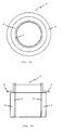
- Fig. 1a shows a plan view of an embodiment of the fire protection cartridge 2 according to the invention.
- Fig. 1b shows a side view of a longitudinal section of the fire protection cartridge 2 in the embodiment according to Fig. 1a ,
- the fire protection cartridge 2 consists of a cartridge body 5, which is designed as a hollow cylinder, for example made of polypropylene.
- the fire protection element 4 is arranged; the fire protection element 4 forms a hollow cylinder whose inner wall is directly adjacent to the outer wall of the cartridge body 5.
- the fire protection element 4 is preferably made of vermicular graphite, which irreversibly expands during the heat ( ⁇ 150 ° C.) occurring in the event of a fire while the cartridge body 5 melts away and, in the extended state, withstands the extreme temperatures of a fire for a prolonged period.
- the Vermiculargrahit für, or the wall thickness of the designed as a hollow cylinder fire protection element 4 is dimensioned such that the fire protection element 4 in the expanded state and molten cartridge body 5, the interior of the fire protection cartridge 2 and thus the outlet nozzle of the floor drain gas-tight.
- the fire protection cartridge 2 is in the Fig. 1a and in Fig.
- FIG. 1b illustrated embodiment as a fire compartment separation (firewall) used, if it is used for example in a drain pipe of a floor drain. So that the fire protection cartridge 2 can be suitably positioned and held in a channel or in a shaft, elastic blocking means 6 are provided at the upper end of the fire protection cartridge 2.
- the locking means 6 are designed as elastic flange arrangements 6 for direct engagement with a drain pipe socket or the like.
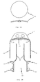
- Fig. 2a shows a view of an integrated in an odor trap 7 according to a first embodiment of the invention fire protection element 11.
- the fire protection element 11 is circular in plan view and slightly bent in cross section, so that the fire protection element 11 can be particularly well attached to the inner wall 10 of an odor trap 8.
- the fire protection element 11 is preferably made of vermicular graphite; However, other materials are also conceivable which expand at elevated temperature and have temperature-resistant or flame-resistant and heat-insulating properties.
- Fig. 2b shows a side view of a longitudinal section of an odor trap 7 according to a first embodiment.
- the fire protection element 11 according to the in Fig. 2a embodiment shown is arranged on the bell inside 10 of the bell body 8 in the odor trap 7.
- the fire protection element 11 has the task to thermally isolate the bell body 8 in a fire, so that the urgent heat from the inlet opening 12 does not cause the odor trap 7 to melt.
- the odor trap 7 is usually made of polypropylene and thus does not last long in the event of fire heat without a special insulation.
- the fire protection element 11 is preferably mounted opposite the inlet opening 12 of the nozzle 9 of the odor trap 7.
- the odor trap 7 further comprises a sealing ring 15 and a flange 16, which allow the interaction of the nozzle 9 with a floor drain nozzle, so that the odor trap 7 can be used gas-tight or waterproof in a floor drain.
- Fig. 3 shows a side view of a longitudinal section of an odor trap 7 according to a second embodiment with an inserted or welded or directly molded fire protection cartridge 2.
- a fire protection element 11 which is preferably arranged opposite the drain opening 12 of the odor trap 7.
- the fire protection element 11 is primarily used for thermal insulation of the bell body from heat, which rises in the event of a fire from the inlet opening 12.
- Another advantage is the fact that the fire protection element 11, if it includes vermicular graphite expands upon exposure to heat and thus at least partially fills the volume between the bell body 8 and the nozzle 9 and closes the odor trap almost gas-tight. This already causes a Brandabschottung or a fire compartment separation.
- a fire protection cartridge 2 is further provided in the lower part of the nozzle 9, which rests flush with the lower edge of the nozzle 9.
- the fire protection cartridge 2 comprises a cartridge body 5 made of PP, which melts in case of fire, and a fire protection element 4, which expands in case of fire, squeezes the melting cartridge body 5 and closes the entire discharge opening 12 gas-tight.
- Fig. 4a shows a side view of a longitudinal section of a floor drain 1 with built-in odor trap 7 and fire cartridge 2 according to the embodiment of Fig. 3 ,
- the odor trap 7 is set in the drain pipe 3 of the floor drain 1 and is positioned by means of a flange 16.
- the sealing ring 15 serves to ensure that Connection between drain pipe 3 and the nozzle 9 of the odor trap 7 is gas or waterproof.
- Fig. 4b shows a side view of a longitudinal section of a floor drain 1 with side inlet 14 and built-in odor trap 7 and a fire protection cartridge 2 according to the embodiment of Fig. 3 .
- the odor trap 7 is inserted into the drain pipe 3 of the floor drain 1 and closes gas or waterproof by means of a sealing ring 15 between the outer wall of the nozzle 9 and the inner wall of the drain pipe socket 3.
- the fire protection cartridge 2 is - as already in Fig. 3 described - inserted into the socket 9 of the drain opening 12 of the odor trap 7, welded or molded.
- elastic blocking means (not explicitly shown) are used for positioning and holding the fire protection cartridge 2 in the socket 9.
- the fire protection cartridge 2 is integrated into the drain pipe 3 of the floor drain 1.
- the blocking means 6 of the fire protection cartridge 2 is designed so that it engages directly or indirectly with the drain pipe socket 3 or nozzle 9 of the odor trap 7.
- Fig. 5 shows a side view of a longitudinal section of an odor trap 7 according to a third Au Unitsform.
- a fire protection element 11 is attached to the bell inside 10 of the bell body 8.
- Fig. 6a shows a side view of a longitudinal section of a floor drain 1 with built-in odor trap 7 according to the embodiment of Fig. 5 and fire protection cartridge 2 according to the embodiment of Fig. 5 ,
- the fire protection cartridge 2 is in this embodiment directly in the drain pipe socket 3 of the floor drain 1 used from below; This can also be done as a further and not separately shown embodiment with a corresponding design of the drain pipe connection 3 from above.
- the drain pipe 3 may protrude more or less deeply into a drain pipe 13. Accordingly, the fire protection cartridge 2 at different positions, that is more or less deeply positioned in the drain pipe 13.
- Fig. 6b shows a side view of a longitudinal section of a floor drain 1 with side inlet 14 and built-in odor trap 7 and fire cartridge 2 according to the embodiment of Fig. 5 ,
- the integration of the odor trap 7 and the fire protection cartridge 2 corresponds to the already in Fig. 6a discussed embodiment and will not be discussed further here.
Landscapes
- Public Health (AREA)
- Health & Medical Sciences (AREA)
- Business, Economics & Management (AREA)
- Hydrology & Water Resources (AREA)
- Engineering & Computer Science (AREA)
- Water Supply & Treatment (AREA)
- Life Sciences & Earth Sciences (AREA)
- Emergency Management (AREA)
- Sink And Installation For Waste Water (AREA)
- Building Environments (AREA)
- Chemical And Physical Treatments For Wood And The Like (AREA)
- Cookers (AREA)
- Fire-Extinguishing Compositions (AREA)
Claims (11)
- Evacuation au sol (1) comprenant une tubulure d'évacuation (3) et un siphon (7) avec un corps en cloche (8) et un tube (9) et un dispositif coupe-feu comme mesure contre une propagation du feu,
caractérisée en ce que
le dispositif coupe-feu comprend une cartouche coupe-feu (2) enfichable et déplaçable dans la tubulure d'écoulement (3) avec au moins un élément coupe-feu (4) qui ferme, en cas d'incendie par action de la chaleur, l'évacuation au sol (1) de manière étanche aux gaz. - Evacuation au sol selon la revendication 1,
caractérisée en ce que
la cartouche coupe-feu (2) représente un cylindre creux. - Evacuation au sol selon la revendication 1 ou 2,
caractérisée en ce que
l'élément coupe-feu (4) comprend du graphite vermiculaire ou un matériau similaire résistant à la température et se dilatant à température plus élevée. - Evacuation au sol selon l'une quelconque des revendications précédentes,
caractérisée par
un moyen de blocage (6) en particulier élastique pour positionner et maintenir la cartouche coupe-feu (2) dans la tubulure d'évacuation (3). - Evacuation au sol selon la revendication 4,
caractérisée en ce que
le moyen de blocage (6) comprend un dispositif à bride élastique (6) ou un dispositif de serrage similaire en particulier à une extrémité de la cartouche coupe-feu (2) pour engagement direct ou indirect avec la tubulure d'évacuation (3). - Evacuation au sol selon l'une quelconque des revendications précédentes,
dans laquelle il est prévu, dans l'évacuation au sol (1), un siphon (7) qui comprend un corps en cloche (8) et un tube (9),
caractérisée en ce que
l'on aménage sur une face interne (10) du corps en cloche (8), en particulier en regard d'une ouverture d'entrée (12) de la tubulure d'évacuation (3), au moins un élément coupe-feu (11) qui isole thermiquement le corps en cloche (8) de l'intérieur contre l'influence de la chaleur. - Evacuation au sol selon l'une quelconque des revendications précédentes, en particulier selon la revendication 6,
caractérisée en ce que
la cartouche coupe-feu (2) est enfichable dans le tube (9) du siphon (7) ou y est raccordé fixe. - Evacuation au sol selon l'une quelconque des revendications précédentes,
caractérisée en ce que
la cartouche coupe-feu (2) est appliquée à niveau par rapport au bord inférieur du tube (9). - Procédé pour équiper ou adapter ultérieurement une évacuation au sol (1) avec un dispositif coupe-feu, constitué des étapes de procédé suivantes :a) retrait d'une cloche d'évacuation standard traditionnelle ou d'un siphon traditionnel de l'évacuation au sol (1) ; etb) enfichage d'une cartouche coupe-feu déplaçable (2) dans la tubulure d'évacuation (3) de l'évacuation au sol (1), dans lequel la cartouche coupe-feu (2) comprend au moins un élément coupe-feu (4), qui ferme l'évacuation au sol (1) de manière étanche aux gaz en cas d'incendie par l'action de la chaleur.
- Procédé selon la revendication 9, comportant une autre étape de procédé suivante selon l'étape de procédé b) :c) remplacement de la cloche d'évacuation standard traditionnelle ou du siphon traditionnel (7) par un corps en cloche (8), dans lequel on aménage sur une face interne (10) du corps en cloche (8), en particulier en regard d'une ouverture d'entrée (12) de la tubulure d'évacuation (3), au moins un élément coupe-feu (11), qui isole thermiquement le corps en cloche (8) de l'intérieur contre l'influence de la chaleur.
- Procédé selon la revendication 9 ou 10,
dans lequel la cartouche coupe-feu (2) est insérée dans le tube (9) du siphon (7) ou lui est reliée de manière fixe, en particulier soudée ou moulée sur celui-ci.
Applications Claiming Priority (5)
| Application Number | Priority Date | Filing Date | Title |
|---|---|---|---|
| DE10161061 | 2001-12-12 | ||
| DE10161061 | 2001-12-12 | ||
| DE2002101287 DE10201287C5 (de) | 2002-01-15 | 2002-01-15 | Bodenablauf |
| DE10201287 | 2002-01-15 | ||
| PCT/EP2002/013870 WO2003053524A1 (fr) | 2001-12-12 | 2002-12-06 | Evacuation coupe-feu |
Publications (2)
| Publication Number | Publication Date |
|---|---|
| EP1453574A1 EP1453574A1 (fr) | 2004-09-08 |
| EP1453574B1 true EP1453574B1 (fr) | 2009-04-29 |
Family
ID=26010762
Family Applications (1)
| Application Number | Title | Priority Date | Filing Date |
|---|---|---|---|
| EP02792923A Expired - Lifetime EP1453574B1 (fr) | 2001-12-12 | 2002-12-06 | Evacuation coupe-feu |
Country Status (5)
| Country | Link |
|---|---|
| EP (1) | EP1453574B1 (fr) |
| AT (1) | ATE429959T1 (fr) |
| AU (1) | AU2002358632A1 (fr) |
| DE (2) | DE20200625U1 (fr) |
| WO (1) | WO2003053524A1 (fr) |
Cited By (1)
| Publication number | Priority date | Publication date | Assignee | Title |
|---|---|---|---|---|
| DE102013107848A1 (de) | 2013-07-23 | 2015-01-29 | ACO Severin Ahlmann GmbH & Co Kommanditgesellschaft | Ablauf |
Families Citing this family (8)
| Publication number | Priority date | Publication date | Assignee | Title |
|---|---|---|---|---|
| DE20200625U1 (de) | 2001-12-12 | 2002-04-11 | Aco Severin Ahlmann Gmbh & Co. Kg, 24768 Rendsburg | Brandschutzablauf |
| DE10219086A1 (de) * | 2002-04-29 | 2003-11-20 | Dallmer Gmbh & Co Kg | Für den Brandschutz einer Ablaufvorrichtung vorgesehenes Bauelement |
| DE10251907B4 (de) * | 2002-11-07 | 2012-02-02 | Basika Entwässerungstechnik GmbH & Co. KG | Ablaufvorrichtung mit Brandschutzeinrichtung |
| DE202007002824U1 (de) | 2007-02-27 | 2008-07-03 | IZEG Informationszentrum Entwässerungstechnik Guss e.V. | Vorrichtung zur Durchführung eines Kunststoffrohres durch eine Decke |
| DE202007008019U1 (de) * | 2007-06-05 | 2008-10-16 | Raimund Höllein Carolinenhütte GmbH | Entwässerungssystem |
| DE102010016647B4 (de) | 2010-04-27 | 2015-09-03 | Aco Severin Ahlmann Gmbh & Co. Kg | Bodenablauf und Geruchsverschlusselement für einen Bodenablauf |
| DE102013102374A1 (de) * | 2013-03-11 | 2014-09-11 | ACO Severin Ahlmann GmbH & Co Kommanditgesellschaft | Bodenablaufmontagevorrichtung |
| HUE065828T2 (hu) * | 2019-02-19 | 2024-06-28 | Dallmer Gmbh & Co Kg | Rendszer tûzvédelmi berendezéssel |
Citations (20)
| Publication number | Priority date | Publication date | Assignee | Title |
|---|---|---|---|---|
| DE1841892U (de) * | 1959-03-04 | 1961-11-16 | Von Roll Ag | Bodenwasserablauf. |
| DE7931426U1 (de) * | 1979-11-07 | 1980-02-21 | Blancke, Robert, 6239 Eppstein | Sinkkasten fuer bodenablaufrinnen |
| DE3001833A1 (de) * | 1980-01-18 | 1981-07-23 | Passavant Werke | Geruchverschluss an ablaeufen, entwaesserungsleitungen o.dgl. |
| DE3218190C2 (de) * | 1982-05-14 | 1984-09-20 | Horst Dr.-Ing. 6200 Wiesbaden Witte | Tragkonstruktion für Hochbauten |
| EP0195189A2 (fr) * | 1985-03-16 | 1986-09-24 | Bernhard Kessel | Siphon en cloche |
| EP0236539A1 (fr) * | 1986-03-07 | 1987-09-16 | Rolf Kuhn GmbH | Manchette de protection contre le feu pour tuyaux |
| US4964180A (en) * | 1989-07-24 | 1990-10-23 | Harbeke Gerold J | Shower strainer mounting assembly |
| WO1992022714A1 (fr) * | 1991-06-19 | 1992-12-23 | Parma Oy | Siphon de sol et ensemble de raccordement, et procede d'installation du siphon de sol |
| DE9300568U1 (de) * | 1993-01-18 | 1993-03-11 | Rolf Kuhn GmbH, 8132 Tutzing | Brandschutzabsperrung für brennbare Rohrleitungen |
| US5299836A (en) * | 1990-03-21 | 1994-04-05 | Woods Robert J | Floor waste fitting support |
| DE4406783A1 (de) * | 1994-03-02 | 1995-09-07 | Dallmer Gmbh & Co | Ablaufarmatur für Decken und Fußböden |
| DE29511265U1 (de) * | 1995-07-12 | 1995-09-21 | Bartholomäus, Gert, 89607 Emerkingen | Brandschutzeinrichtung zur Abschottung einer Lüftungsrohrleitung |
| DE3639285C2 (de) * | 1986-11-18 | 1995-11-09 | Bernhard Kessel | Bodenablauf |
| DE29704346U1 (de) * | 1996-08-01 | 1997-06-05 | Wildeboer, Werner, 26826 Weener | Brandschutzeinrichtung für durch Wände und/oder Decken eines Gebäudes geführte Leitungen einer Klima- und/oder Be- bzw. Entlüftungsanlage |
| DE29712909U1 (de) * | 1997-07-15 | 1997-10-16 | Lunos-Lüftung GmbH & Co Ventilatoren KG, 13593 Berlin | Selbsttätig schließende Brandschutzeinrichtung |
| DE4430039C2 (de) * | 1994-08-24 | 1998-07-16 | Johann Franz Wach | Bodenablaufelement zum Einbau in eine Geschoßbodendurchführung |
| DE20017115U1 (de) * | 2000-10-04 | 2001-02-22 | Züll, Armin, 74229 Oedheim | Rohrmanschette in brandabschnittsbegrenzenden Bauteilen |
| DE20101589U1 (de) * | 2001-01-31 | 2001-03-22 | Franz Viegener II GmbH & Co. KG, 57439 Attendorn | Ablauf |
| DE10033306A1 (de) * | 1999-11-02 | 2001-05-03 | Kamleithner Maly Uta | Brandschutz-Einrichtung |
| DE19964021A1 (de) * | 1999-12-30 | 2001-07-05 | Friatec Ag | Brandschutz-Sperrvorrichtung |
Family Cites Families (5)
| Publication number | Priority date | Publication date | Assignee | Title |
|---|---|---|---|---|
| FR2252736A5 (fr) * | 1973-11-27 | 1975-06-20 | Lambert Jean | |
| US5183070A (en) * | 1991-04-29 | 1993-02-02 | Cornwall Kenneth R | Firestop device for flammable floor construction |
| US5191990A (en) * | 1991-06-24 | 1993-03-09 | Bs&B Safety Systems, Inc. | Flash gas venting and flame arresting apparatus |
| DE20200625U1 (de) | 2001-12-12 | 2002-04-11 | Aco Severin Ahlmann Gmbh & Co. Kg, 24768 Rendsburg | Brandschutzablauf |
| DE10201287C5 (de) | 2002-01-15 | 2009-02-19 | Aco Severin Ahlmann Gmbh & Co. Kg | Bodenablauf |
-
2002
- 2002-01-16 DE DE20200625U patent/DE20200625U1/de not_active Expired - Lifetime
- 2002-12-06 EP EP02792923A patent/EP1453574B1/fr not_active Expired - Lifetime
- 2002-12-06 AU AU2002358632A patent/AU2002358632A1/en not_active Abandoned
- 2002-12-06 WO PCT/EP2002/013870 patent/WO2003053524A1/fr not_active Ceased
- 2002-12-06 DE DE50213506T patent/DE50213506D1/de not_active Expired - Lifetime
- 2002-12-06 AT AT02792923T patent/ATE429959T1/de not_active IP Right Cessation
Patent Citations (20)
| Publication number | Priority date | Publication date | Assignee | Title |
|---|---|---|---|---|
| DE1841892U (de) * | 1959-03-04 | 1961-11-16 | Von Roll Ag | Bodenwasserablauf. |
| DE7931426U1 (de) * | 1979-11-07 | 1980-02-21 | Blancke, Robert, 6239 Eppstein | Sinkkasten fuer bodenablaufrinnen |
| DE3001833A1 (de) * | 1980-01-18 | 1981-07-23 | Passavant Werke | Geruchverschluss an ablaeufen, entwaesserungsleitungen o.dgl. |
| DE3218190C2 (de) * | 1982-05-14 | 1984-09-20 | Horst Dr.-Ing. 6200 Wiesbaden Witte | Tragkonstruktion für Hochbauten |
| EP0195189A2 (fr) * | 1985-03-16 | 1986-09-24 | Bernhard Kessel | Siphon en cloche |
| EP0236539A1 (fr) * | 1986-03-07 | 1987-09-16 | Rolf Kuhn GmbH | Manchette de protection contre le feu pour tuyaux |
| DE3639285C2 (de) * | 1986-11-18 | 1995-11-09 | Bernhard Kessel | Bodenablauf |
| US4964180A (en) * | 1989-07-24 | 1990-10-23 | Harbeke Gerold J | Shower strainer mounting assembly |
| US5299836A (en) * | 1990-03-21 | 1994-04-05 | Woods Robert J | Floor waste fitting support |
| WO1992022714A1 (fr) * | 1991-06-19 | 1992-12-23 | Parma Oy | Siphon de sol et ensemble de raccordement, et procede d'installation du siphon de sol |
| DE9300568U1 (de) * | 1993-01-18 | 1993-03-11 | Rolf Kuhn GmbH, 8132 Tutzing | Brandschutzabsperrung für brennbare Rohrleitungen |
| DE4406783A1 (de) * | 1994-03-02 | 1995-09-07 | Dallmer Gmbh & Co | Ablaufarmatur für Decken und Fußböden |
| DE4430039C2 (de) * | 1994-08-24 | 1998-07-16 | Johann Franz Wach | Bodenablaufelement zum Einbau in eine Geschoßbodendurchführung |
| DE29511265U1 (de) * | 1995-07-12 | 1995-09-21 | Bartholomäus, Gert, 89607 Emerkingen | Brandschutzeinrichtung zur Abschottung einer Lüftungsrohrleitung |
| DE29704346U1 (de) * | 1996-08-01 | 1997-06-05 | Wildeboer, Werner, 26826 Weener | Brandschutzeinrichtung für durch Wände und/oder Decken eines Gebäudes geführte Leitungen einer Klima- und/oder Be- bzw. Entlüftungsanlage |
| DE29712909U1 (de) * | 1997-07-15 | 1997-10-16 | Lunos-Lüftung GmbH & Co Ventilatoren KG, 13593 Berlin | Selbsttätig schließende Brandschutzeinrichtung |
| DE10033306A1 (de) * | 1999-11-02 | 2001-05-03 | Kamleithner Maly Uta | Brandschutz-Einrichtung |
| DE19964021A1 (de) * | 1999-12-30 | 2001-07-05 | Friatec Ag | Brandschutz-Sperrvorrichtung |
| DE20017115U1 (de) * | 2000-10-04 | 2001-02-22 | Züll, Armin, 74229 Oedheim | Rohrmanschette in brandabschnittsbegrenzenden Bauteilen |
| DE20101589U1 (de) * | 2001-01-31 | 2001-03-22 | Franz Viegener II GmbH & Co. KG, 57439 Attendorn | Ablauf |
Cited By (2)
| Publication number | Priority date | Publication date | Assignee | Title |
|---|---|---|---|---|
| DE102013107848A1 (de) | 2013-07-23 | 2015-01-29 | ACO Severin Ahlmann GmbH & Co Kommanditgesellschaft | Ablauf |
| DE102013107848B4 (de) * | 2013-07-23 | 2015-08-27 | ACO Severin Ahlmann GmbH & Co Kommanditgesellschaft | Ablauf |
Also Published As
| Publication number | Publication date |
|---|---|
| AU2002358632A1 (en) | 2003-07-09 |
| EP1453574A1 (fr) | 2004-09-08 |
| DE50213506D1 (de) | 2009-06-10 |
| ATE429959T1 (de) | 2009-05-15 |
| DE20200625U1 (de) | 2002-04-11 |
| WO2003053524A1 (fr) | 2003-07-03 |
Similar Documents
| Publication | Publication Date | Title |
|---|---|---|
| EP3460930B1 (fr) | Boîtier d'installation pour l'installation électrique | |
| WO2007137692A2 (fr) | Raccord de tuyau de protection contre l'incendie, raccordement de tuyau de protection contre l'incendie, et système de tuyauterie | |
| EP1362961B1 (fr) | Elément de construction pour la protection coupe-feu d' un dispositif d' écoulement et dispositif d'écoulement comprenant un tel élement | |
| EP2105544B1 (fr) | Dispositif sanitaire doté d'un élément intumescent | |
| DE10201287B4 (de) | Bodenablauf | |
| EP1453574A1 (fr) | Evacuation coupe-feu | |
| EP3280019B1 (fr) | Boitier d'installation pour installation electrique | |
| EP3282164A1 (fr) | Système de conduit | |
| DE2947593A1 (de) | Feuerschutz-abschlussanordnung fuer eine rohrleitung | |
| DE102005046149B4 (de) | Vorrichtung zum Abführen von Oberflächenwasser und zum Brandschutz | |
| DE102007010682B4 (de) | Ein- bzw. Anbaurahmen für eine Brandschutzklappe | |
| EP2402520B1 (fr) | Pare-feu pour siphon de sol | |
| AT410283B (de) | Brandschutz-einrichtung | |
| EP0724676B1 (fr) | Element d'ecoulement destine a etre monte notamment dans des sols en beton | |
| DE20302159U1 (de) | Bauelement für den Brandschutz einer Ablaufvorrichtung sowie Ablaufvorrichtung mit einem derartigen Bauelement | |
| DE10251907B4 (de) | Ablaufvorrichtung mit Brandschutzeinrichtung | |
| DE102010016647B4 (de) | Bodenablauf und Geruchsverschlusselement für einen Bodenablauf | |
| EP1577453B1 (fr) | Bouche d'égout | |
| EP1785540B1 (fr) | Dispositif pour le drainage des eaux de surface avec protection de feu | |
| EP2148124B1 (fr) | Dispositif de protection contre les flammes pour une jonction de tuyaux et jonction de tuyaux | |
| EP1801481B1 (fr) | Raccord de tuyau, pour tuyau de décharge d'eau usée | |
| DE10323589A1 (de) | Brand- und Schallschutzvorrichtungen für Rohrleitungssysteme sowie Brand- und Schallschutzprofile und -hülsen | |
| EP3312958B1 (fr) | Boîtier d'installation pour l'installation électrique | |
| EP1528307A2 (fr) | Bouche d'égout avec matière ignifuge | |
| DE20221726U1 (de) | Ablaufvorrichtung mit Brandschutzeinrichtung |
Legal Events
| Date | Code | Title | Description |
|---|---|---|---|
| PUAI | Public reference made under article 153(3) epc to a published international application that has entered the european phase |
Free format text: ORIGINAL CODE: 0009012 |
|
| 17P | Request for examination filed |
Effective date: 20040528 |
|
| AK | Designated contracting states |
Kind code of ref document: A1 Designated state(s): AT BE BG CH CY CZ DE DK EE ES FI FR GB GR IE IT LI LU MC NL PT SE SI SK TR |
|
| AX | Request for extension of the european patent |
Extension state: AL LT LV MK RO |
|
| TPAC | Observations filed by third parties |
Free format text: ORIGINAL CODE: EPIDOSNTIPA |
|
| TPAC | Observations filed by third parties |
Free format text: ORIGINAL CODE: EPIDOSNTIPA |
|
| 17Q | First examination report despatched |
Effective date: 20080328 |
|
| GRAP | Despatch of communication of intention to grant a patent |
Free format text: ORIGINAL CODE: EPIDOSNIGR1 |
|
| GRAS | Grant fee paid |
Free format text: ORIGINAL CODE: EPIDOSNIGR3 |
|
| GRAA | (expected) grant |
Free format text: ORIGINAL CODE: 0009210 |
|
| AK | Designated contracting states |
Kind code of ref document: B1 Designated state(s): AT BE BG CH CY CZ DE DK EE ES FI FR GB GR IE IT LI LU MC NL PT SE SI SK TR |
|
| REG | Reference to a national code |
Ref country code: GB Ref legal event code: FG4D Free format text: NOT ENGLISH |
|
| REG | Reference to a national code |
Ref country code: CH Ref legal event code: EP |
|
| REF | Corresponds to: |
Ref document number: 50213506 Country of ref document: DE Date of ref document: 20090610 Kind code of ref document: P |
|
| REG | Reference to a national code |
Ref country code: IE Ref legal event code: FG4D |
|
| NLV1 | Nl: lapsed or annulled due to failure to fulfill the requirements of art. 29p and 29m of the patents act | ||
| PG25 | Lapsed in a contracting state [announced via postgrant information from national office to epo] |
Ref country code: PT Free format text: LAPSE BECAUSE OF FAILURE TO SUBMIT A TRANSLATION OF THE DESCRIPTION OR TO PAY THE FEE WITHIN THE PRESCRIBED TIME-LIMIT Effective date: 20090829 Ref country code: FI Free format text: LAPSE BECAUSE OF FAILURE TO SUBMIT A TRANSLATION OF THE DESCRIPTION OR TO PAY THE FEE WITHIN THE PRESCRIBED TIME-LIMIT Effective date: 20090429 Ref country code: ES Free format text: LAPSE BECAUSE OF FAILURE TO SUBMIT A TRANSLATION OF THE DESCRIPTION OR TO PAY THE FEE WITHIN THE PRESCRIBED TIME-LIMIT Effective date: 20090809 |
|
| PG25 | Lapsed in a contracting state [announced via postgrant information from national office to epo] |
Ref country code: NL Free format text: LAPSE BECAUSE OF FAILURE TO SUBMIT A TRANSLATION OF THE DESCRIPTION OR TO PAY THE FEE WITHIN THE PRESCRIBED TIME-LIMIT Effective date: 20090429 Ref country code: SE Free format text: LAPSE BECAUSE OF FAILURE TO SUBMIT A TRANSLATION OF THE DESCRIPTION OR TO PAY THE FEE WITHIN THE PRESCRIBED TIME-LIMIT Effective date: 20090729 Ref country code: SI Free format text: LAPSE BECAUSE OF FAILURE TO SUBMIT A TRANSLATION OF THE DESCRIPTION OR TO PAY THE FEE WITHIN THE PRESCRIBED TIME-LIMIT Effective date: 20090429 |
|
| REG | Reference to a national code |
Ref country code: IE Ref legal event code: FD4D |
|
| PG25 | Lapsed in a contracting state [announced via postgrant information from national office to epo] |
Ref country code: EE Free format text: LAPSE BECAUSE OF FAILURE TO SUBMIT A TRANSLATION OF THE DESCRIPTION OR TO PAY THE FEE WITHIN THE PRESCRIBED TIME-LIMIT Effective date: 20090429 Ref country code: CZ Free format text: LAPSE BECAUSE OF FAILURE TO SUBMIT A TRANSLATION OF THE DESCRIPTION OR TO PAY THE FEE WITHIN THE PRESCRIBED TIME-LIMIT Effective date: 20090429 Ref country code: DK Free format text: LAPSE BECAUSE OF FAILURE TO SUBMIT A TRANSLATION OF THE DESCRIPTION OR TO PAY THE FEE WITHIN THE PRESCRIBED TIME-LIMIT Effective date: 20090429 Ref country code: IE Free format text: LAPSE BECAUSE OF FAILURE TO SUBMIT A TRANSLATION OF THE DESCRIPTION OR TO PAY THE FEE WITHIN THE PRESCRIBED TIME-LIMIT Effective date: 20090429 |
|
| PG25 | Lapsed in a contracting state [announced via postgrant information from national office to epo] |
Ref country code: SK Free format text: LAPSE BECAUSE OF FAILURE TO SUBMIT A TRANSLATION OF THE DESCRIPTION OR TO PAY THE FEE WITHIN THE PRESCRIBED TIME-LIMIT Effective date: 20090429 |
|
| PLBE | No opposition filed within time limit |
Free format text: ORIGINAL CODE: 0009261 |
|
| STAA | Information on the status of an ep patent application or granted ep patent |
Free format text: STATUS: NO OPPOSITION FILED WITHIN TIME LIMIT |
|
| PG25 | Lapsed in a contracting state [announced via postgrant information from national office to epo] |
Ref country code: BG Free format text: LAPSE BECAUSE OF FAILURE TO SUBMIT A TRANSLATION OF THE DESCRIPTION OR TO PAY THE FEE WITHIN THE PRESCRIBED TIME-LIMIT Effective date: 20090729 |
|
| 26N | No opposition filed |
Effective date: 20100201 |
|
| BERE | Be: lapsed |
Owner name: ACO SEVERIN AHLMANN G.M.B.H. & CO. KG Effective date: 20091231 |
|
| PG25 | Lapsed in a contracting state [announced via postgrant information from national office to epo] |
Ref country code: MC Free format text: LAPSE BECAUSE OF NON-PAYMENT OF DUE FEES Effective date: 20100701 |
|
| REG | Reference to a national code |
Ref country code: CH Ref legal event code: PL |
|
| GBPC | Gb: european patent ceased through non-payment of renewal fee |
Effective date: 20091206 |
|
| REG | Reference to a national code |
Ref country code: FR Ref legal event code: ST Effective date: 20100831 |
|
| PG25 | Lapsed in a contracting state [announced via postgrant information from national office to epo] |
Ref country code: LI Free format text: LAPSE BECAUSE OF NON-PAYMENT OF DUE FEES Effective date: 20091231 Ref country code: CH Free format text: LAPSE BECAUSE OF NON-PAYMENT OF DUE FEES Effective date: 20091231 Ref country code: BE Free format text: LAPSE BECAUSE OF NON-PAYMENT OF DUE FEES Effective date: 20091231 Ref country code: GR Free format text: LAPSE BECAUSE OF FAILURE TO SUBMIT A TRANSLATION OF THE DESCRIPTION OR TO PAY THE FEE WITHIN THE PRESCRIBED TIME-LIMIT Effective date: 20090730 Ref country code: FR Free format text: LAPSE BECAUSE OF NON-PAYMENT OF DUE FEES Effective date: 20091231 |
|
| PG25 | Lapsed in a contracting state [announced via postgrant information from national office to epo] |
Ref country code: GB Free format text: LAPSE BECAUSE OF NON-PAYMENT OF DUE FEES Effective date: 20091206 |
|
| PG25 | Lapsed in a contracting state [announced via postgrant information from national office to epo] |
Ref country code: IT Free format text: LAPSE BECAUSE OF FAILURE TO SUBMIT A TRANSLATION OF THE DESCRIPTION OR TO PAY THE FEE WITHIN THE PRESCRIBED TIME-LIMIT Effective date: 20090429 |
|
| PG25 | Lapsed in a contracting state [announced via postgrant information from national office to epo] |
Ref country code: LU Free format text: LAPSE BECAUSE OF NON-PAYMENT OF DUE FEES Effective date: 20091206 |
|
| PG25 | Lapsed in a contracting state [announced via postgrant information from national office to epo] |
Ref country code: AT Free format text: LAPSE BECAUSE OF NON-PAYMENT OF DUE FEES Effective date: 20091206 |
|
| PG25 | Lapsed in a contracting state [announced via postgrant information from national office to epo] |
Ref country code: TR Free format text: LAPSE BECAUSE OF FAILURE TO SUBMIT A TRANSLATION OF THE DESCRIPTION OR TO PAY THE FEE WITHIN THE PRESCRIBED TIME-LIMIT Effective date: 20090429 |
|
| PG25 | Lapsed in a contracting state [announced via postgrant information from national office to epo] |
Ref country code: CY Free format text: LAPSE BECAUSE OF FAILURE TO SUBMIT A TRANSLATION OF THE DESCRIPTION OR TO PAY THE FEE WITHIN THE PRESCRIBED TIME-LIMIT Effective date: 20090429 |
|
| PGFP | Annual fee paid to national office [announced via postgrant information from national office to epo] |
Ref country code: DE Payment date: 20211220 Year of fee payment: 20 |
|
| REG | Reference to a national code |
Ref country code: DE Ref legal event code: R071 Ref document number: 50213506 Country of ref document: DE |