EP1453654B1 - A device for processing a three dimensional structure into a substrate - Google Patents
A device for processing a three dimensional structure into a substrate Download PDFInfo
- Publication number
- EP1453654B1 EP1453654B1 EP02803341A EP02803341A EP1453654B1 EP 1453654 B1 EP1453654 B1 EP 1453654B1 EP 02803341 A EP02803341 A EP 02803341A EP 02803341 A EP02803341 A EP 02803341A EP 1453654 B1 EP1453654 B1 EP 1453654B1
- Authority
- EP
- European Patent Office
- Prior art keywords
- substrate
- tool
- plane
- layer
- force absorbing
- Prior art date
- Legal status (The legal status is an assumption and is not a legal conclusion. Google has not performed a legal analysis and makes no representation as to the accuracy of the status listed.)
- Expired - Lifetime
Links
Images



Classifications
-
- B—PERFORMING OPERATIONS; TRANSPORTING
- B44—DECORATIVE ARTS
- B44B—MACHINES, APPARATUS OR TOOLS FOR ARTISTIC WORK, e.g. FOR SCULPTURING, GUILLOCHING, CARVING, BRANDING, INLAYING
- B44B5/00—Machines or apparatus for embossing decorations or marks, e.g. embossing coins
- B44B5/0004—Machines or apparatus for embossing decorations or marks, e.g. embossing coins characterised by the movement of the embossing tool(s), or the movement of the work, during the embossing operation
- B44B5/0009—Rotating embossing tools
-
- B—PERFORMING OPERATIONS; TRANSPORTING
- B29—WORKING OF PLASTICS; WORKING OF SUBSTANCES IN A PLASTIC STATE IN GENERAL
- B29C—SHAPING OR JOINING OF PLASTICS; SHAPING OF MATERIAL IN A PLASTIC STATE, NOT OTHERWISE PROVIDED FOR; AFTER-TREATMENT OF THE SHAPED PRODUCTS, e.g. REPAIRING
- B29C59/00—Surface shaping of articles, e.g. embossing; Apparatus therefor
- B29C59/002—Component parts, details or accessories; Auxiliary operations
-
- B—PERFORMING OPERATIONS; TRANSPORTING
- B44—DECORATIVE ARTS
- B44B—MACHINES, APPARATUS OR TOOLS FOR ARTISTIC WORK, e.g. FOR SCULPTURING, GUILLOCHING, CARVING, BRANDING, INLAYING
- B44B5/00—Machines or apparatus for embossing decorations or marks, e.g. embossing coins
- B44B5/02—Dies; Accessories
-
- B—PERFORMING OPERATIONS; TRANSPORTING
- B29—WORKING OF PLASTICS; WORKING OF SUBSTANCES IN A PLASTIC STATE IN GENERAL
- B29C—SHAPING OR JOINING OF PLASTICS; SHAPING OF MATERIAL IN A PLASTIC STATE, NOT OTHERWISE PROVIDED FOR; AFTER-TREATMENT OF THE SHAPED PRODUCTS, e.g. REPAIRING
- B29C59/00—Surface shaping of articles, e.g. embossing; Apparatus therefor
- B29C59/02—Surface shaping of articles, e.g. embossing; Apparatus therefor by mechanical means, e.g. pressing
-
- B—PERFORMING OPERATIONS; TRANSPORTING
- B29—WORKING OF PLASTICS; WORKING OF SUBSTANCES IN A PLASTIC STATE IN GENERAL
- B29C—SHAPING OR JOINING OF PLASTICS; SHAPING OF MATERIAL IN A PLASTIC STATE, NOT OTHERWISE PROVIDED FOR; AFTER-TREATMENT OF THE SHAPED PRODUCTS, e.g. REPAIRING
- B29C59/00—Surface shaping of articles, e.g. embossing; Apparatus therefor
- B29C59/02—Surface shaping of articles, e.g. embossing; Apparatus therefor by mechanical means, e.g. pressing
- B29C59/04—Surface shaping of articles, e.g. embossing; Apparatus therefor by mechanical means, e.g. pressing using rollers or endless belts
Definitions
- This invention relates generally to a device and a process for processing a substrate, e.g. forming a three-dimensional structure, nano-structure, hologram or similar relief diffraction pattern into a substrate by use of a re-configurable mould.
- Cutting is done in different ways e.g. punching.
- the cutting machine is provided with co-operating edges used to cut the material.
- the tool with the cutting edges need to be renewed or renovated often, due to tear and wear of the tool. This makes the process relatively expensive.
- a mould holds a liquid resin on the substrate during curing of the resin whereby the resin forms the microstructure.
- the mould may be provided with a rotating drum having a three-dimensional relief pattern forming the microstructure, or the mould may be provided with a planar plate having a relief pattern attached to one side.
- the tolerances must be low and accordingly, the cost for making a mould is relatively high.
- the moulds have to be replaced after a number of moulding cycles, as the moulds are incorporated e.g. in rotational drums for mass replication of holograms, the costs for replacing moulds being high.
- the rigidity disables the machine to take up tolerances occurring in the substrate.
- a metal plate will usually have a non-planar surface.
- the deviations of the non-planar surface may easily be visually detectable in the structure.
- the non-planarity of the plate may be replicated in a non-even embossing depth, which gives visually detectable uneven reflection from the surface of the structure.
- JP 5624116 discloses a stamping convex die for stamping letters and patterns consisting of an elastic material on a stamp block opposite to a heater through a shock absorber, such as a sponge rubber.
- the convex die is depressed onto a sealer material by moving the stamp block downward, thereby sealing and stamping simultaneously.
- WO 98 38137 discloses a process and a device for manufacturing networks of microlenses.
- a number of molds having grooved non-malleable surfaces are inserted between a number of plates of malleable material. They are placed in a heated housing, and a roughly uniform pressure is applied perpendicular to the surfaces of the plates, which causes production of convex surfaces of microlenses on the sides of the plates.
- WO 00 40421 discloses a method of replicating a surface relief in a non-metallic layer held by a metal substrate.
- the surface relief is replicated In the layer by pressing an object comprtsing a surface into said layer so as to change surface properties of the layer, the surface relief forming part of the surface of the object.
- US 4,615,204 discloses a drawing apparatus of the type In which a lower punch slide moves upward to draw a blank damped between a moveable die and a stationary blank holder.
- the apparatus comprises an adjustable ram, which is electrically driven to move upward and downward for thereby adjusting the bottom dead position of the punch.
- the upper end of the punch is made substantially flush with the upper end surface of the blank holder when the punch Is In its bottom dead position.
- the present invention relates to a device according to claim 1.
- the flexible force absorbing means is adapted to equalise the pressure along the core and/or too, so that possible sporadic unevenness along the length of the core and/or tool do not result in a higher local pressure in the area of the unevenness, as the force absorbing means will absorb/equalise such high pressure.
- the flexible force absorbing means may be resilient. Thus the flexible force absorbing means may return to an initial position when pressure applied from the tool plane and/or the reaction plane is removed, In some embodiments the flexible force absorbing means may be chosen such that it is only elastically deformed when pressure is applied to said means. A reversible process may take place when the flexible force absorbing means perform the following steps; uncompressed state (prior to application of pressure from the tools) - compressed state (during application of pressure from the tools) - uncompressed state (subsequent to application of pressure from the tools). As the flexible force absorbing means may be only elastically deformed the thickness of the means may be the same before and after application of pressure.
- the means When the flexible force absorbing means is resillent the means may have spring like properties.
- An advantage of the resilient absorbing means may be that said means may be re-used contrary to non-flexible absorbing means which may be plastically deformed and thus must be replaced by a non-plastically-deformed piece prior to further use of the device.
- the flexible force absorbing mean may be adapted to be elastically deformable, so as to locally absorb the forces applied by the planes to a substrate.
- the flexible force absorbing means may be adapted to be elastically deformable at room temperature and/or at atmospheric pressure.
- room temperature may be between 0, degrees Celsius and 100 degrees Celsius.
- it may be essential that the temperature of the air/space surrounding the device is such that a worker may operate the machine without encapsulating the machine or without dressing the worker in clothing protecting him from extreme temperatures.
- Analogously it may be essential that the pressure is such that a worker may operate the machine without encapsulating the machine and/or the worker.
- atmospheric pressure may, in this application, be seen to be pressures in which a human being can survive for a longer or shorter period of time.
- the tool plane and/or the reaction plane may be heated during operation. A substrate being processed may be heated so as to soften the substrate.
- the operation speed may be 0-10.000 meters of substrate per hour such as 2.000-8.000 meters per hour, such as 4.000-5.000 meters per hour.
- the work pieces/substrates may be plates of material e.g. plastic or metal, being 1 meter long.
- the pieces/substrates may be coils.
- the movements of the tool plane and the reaction plane may be synchronised vertically and/or hortzontally. If the two planes are provided as a stamping process means for moving a work piece through the stamping process may be synchronised with the stamping process. If the two planes are provided as one or more drums for rotative processing of the first layer said drums may be synchronised.
- a tool may comprise a tool plane and a reaction plane provided with co-operating edges for cutting a substrate.
- the tool may be used for cutting such as die-cutting or punching e.g. in an eccentric press, but could also be used in a rotative drum adapted to cut substrate with co-operating edges.
- Said drum may be adapted to cut and/or shape e.g. emboss a microstructure into a substrate.
- the tool may also be used for micro embossing, macro embossing, marking up cutting-lines on a sheet/plate.
- Another embodiment comprises a tool having a tool plane and a reaction plane wherein at least one of either the tool plane or the reaction plane may be adapted to shape at least a first layer of the substrate into a predefined form.
- Such tool may be used in a hydraulic press for shaping a substrate, but could also be used in a rolling process.
- the tool plane could be a hard plane surface corresponding to the known tool planes of regular stamping machines.
- the stamp could be moved up and down by a rigid cam disc, linear actuators or the like.
- the stamp should provide a sufficient pressure against the substrate and the reaction plane to emboss the structure into the substrate.
- the tool plane or the reaction plane could both be provided with rigidity since the flexible force absorbing means of the tool plane or the reaction plane or both the tool plane and the reaction plane, will take up tolerances.
- the flexible force absorbing means are provided so that the flexibility may be changed.
- the flexible force absorbing means are provided in the form of a resilient adhesive tape attached to the surface of the tool plane and/or to the surface of the reaction plane forming a force absorbing layer of the device. The resiliency and thus the capability of the device to take up tolerances may easily be changed e.g. by changing the type of adhesive tape of the thickness of the adhesive tape.
- the flexible force absorbing means may comprise at least one force absorbing layer provided in the multiple layer construction and/or being attached to the reaction plane.
- Both the tool plane and the reaction plane may be provided with a force absorbing layer.
- the flexible force absorbing layer is provided in the multiple layer construction between the core and the tool.
- This embodiment is advantageous, as the absorbing layer then absorbs all sporadic unevenness along the entire length of the core and/or tool.
- the flexible force absorbing means may, according to another embodiment, be provided as a hard plane e.g. of metal being attached to the surface of the tool plan and/or the reaction plane and provided with bouncing springs facing the tool plane and/or the reaction plane.
- the springs may either be provided with an adjustable characteristic or be detachably mounted for replacement with springs having a characteristic matching the individual embossing tasks and substrate materials.
- the tool plane is a cylindrically shaped drum for rotative embossing of the tree dimensional structure and the reaction plane is likewise a cylindrical drum or nip roll for providing the necessary counter pressure.
- the force absorbing layer will be capable of raking up at least a substantial part of the deviation by compression of the layer. It will further be preferred that the material for the force absorbing layer is selected so that the force required to compress the material should be less than the force required for embossing the structure Into the substrate, i.e. the non-compressed flexible layer should be softer than the surface of the substrate.
- the force absorbing layer is selected with a thickness In the range of 0,1-5 mm, such as 0,2-4,5 mm, such as 0,3-4,0 mm such as 0,4-3,5 mm, such as 0,53 mm, such as 0,6-2,5 mm, such as 0,7-2,0 mm, such as in the size of 1,5 mm.
- the absorbing layer is selected with an elasticity enabling the layer to provide a force to the hard substrate, which force extends the yield point of the hard substrate at a given rate of compression ⁇ , and wherein the thickness of the flexible force absorbing layer at that rate of compression ⁇ extents the planar deviation ⁇ .
- the force absorbing layer could be provided in the form of a double sided adhesive tape for attaching at least one tool, such as a shim, to the outer surface of the core, e.g. selected with a thickness In the range of 0,1-0,5 mm, such as In the range of 0,20-0,4 mm, such as in the range of 0,22-0.3 mm, such as In the range of 0,22-0,26 mm. such as 0,24 mm.
- the core may be provided with a steel surface, so that it Is easy to provide an adhesive tape having the necessary attachment strength.
- the double sided adhesive tape 3M-type 9586 F gives a sufficient adhesion to steel.
- a roughness in the range of 1-100 microns of the steel surface will be preferred. Thereby it will be possible to provide an adhesion to steel in the range of 6-12 N/cm, such as in the range of 7-11 N/cm, such as in the range of 8-10 N/cm, such as 9 N/cm.
- one or both sides of the double sided adhesive tape are provided with an acrylic based adhesive and preferably the tape is provided with a dynamic shear in the range of 50-100 N/cm 2 , e.g. in the size of 70 N/cm 2 .
- the adhesive layer of the tape may be provided with a permanent adhesion so that it will be possible to reuse the tape and to refit the shims to the flexible layer, which will make refitting easler and faster.
- the invention provides a much more flexible device, as the tool can be changed very easy.
- the processing may comprise embossing of a three-dimensional structure into the substrate, such as a nano-structure into the substrate, or it may comprise embossing of a nano-structure into a metallic substrate.
- the tool plane may be a drum for rotative processing of a first layer of a multiple layer substrate, the first layer having a first degree of hardness and the succeeding layers having a second degree of hardness, said drum having:
- the present invention relates to a method according to claim 27
- the substrate mentioned in connection with any of the above-mentioned aspects may be selected from the group consisting of lacquers, carton, cardboard, polymers, printing inks, plastics, metal such as tin, aluminium, copper, lead, steel.
- the Brinell-hardness (HB 10) of the substrate may range from 10 N/mm 2 to 1000 N/mm 2 .
- the present invention provides a technique for processing a substrate at high speeds, (such as 1-2 meter sheet material per hour) and at room-temperature.
- the technique should be applicable for high-speed production lines for manufacturing e.g. food containers.
- the pressure applied to the substrate should be so high that the wanted shape is embossed or punched or cut in the substrate.
- the pressure is within the range or 981-9810 N/cm 2 (100-1000 kg/cm 2 ).
- the combination of pressure and type of substrate with be chosen so as to obtain the best result of the processing.
- a device according to the invention comprises an embossing roll 3 and a nip roll 7.
- the nip roll provides the necessary counter pressure - the surface of the nip roller corresponds to the reaction plane.
- the embossing roll is provided with a number of shims 1 attached to the roll by a resillent adhesive tape 2.
- the embossing roll and the nip roll is carried by bearings 4, 6.
- the embossing roll 3) Is provided with means for adjusting the pressure between the embossing roll and the nip roll by adjusting the gap between the rolls.
- the absorbing layer 5 in the bearing absorbs the pressure.
- the absorbing layer 5 may be distorted by predetermined "retaining force" In order to control the upwards movement of the embossing roll 3 when introducing a sheet material 8 (or any other material to be processed) between the rolls 3, 7.
- the embossing roll may be held by a servo driven guide rail enabling the roll to be shifted linearly.
- One or both of the embossing roll and/or the nip roll is rotated by power driven means.
- the rolls are rotated in a synchronised fashion wherein the peripheral speed of the rolls are adjusted to the speed of previous and/or succeeding rolls or sets of rolls in a process machine for printing and embossing substrates from a coil.
- both of the rolls may preferably be driven by synchronised powered means so that the peripheral speed of the rolls is the same.
- the diameter of the rolls is the same.
- Regular lacquer machines or printing machines which provides a setup of rolls and nip rolls according to the above description exits on the market. However, none of these machines are provided with shims attached to the rolls as described above.
- a plurality of shims may be attached to the surface of one single embossing roll.
- the use of the surface area of the roll may be optimised and many replicas may be embossed for each round of the embossing roll.
- the shims attached to one roll (or tool plane) may be identical or they may be different.
- the resilient adhesive tape 2 is compassed during the embossing of the hologram into the substrate.
- the wedge 9 serves for attaching a wrapping sheet to the surface of the roll. In this way it is even faster to change the replica to be embossed by simply removing one wrapping sheet holding a number of shims attached to the sheet by resilient adhesive tape.
- the wrapping holding a number of shims may be provided with sufficient resiliency to provide the flexibility. Thereby the shims may be attached directly to the wrapping sheet and thereby a number of sheets may be replaced simultaneously by replacing the wrapping sheet.
- Fig. 3 shows an embodiment of the device wherein the drum is replaced with a stamp capable of moving along a vertical axis towards sheet material 8.
- the stamp is provided with at least one shim 1 being attached to the stamp by a resilient adhesive tape 2.
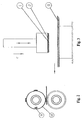
- Fig. 4, 5 and 6 show the principles of embossing according to the present invention.
- Fig. 4 shows the principles of appliying a force from a movable plane, e.g. a drum or stamp through a flexible material, e.g. a resilient adhesive tape, foam rubber or similar resilient means to a tool (shim) for embossing a three dimensional structure into a substrate.
- the reaction plane serves for providing the necessary counter pressure against the stamp or drum.
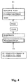
- Fig. 5 expresses the force increase resulting from the compression of the resilient tape or similar flexible means.
- the flexible layer will absorb non-planarity and tolerances of the surface of the substrate. ⁇ h expresses the permanent deformation of the substrate.
- Fig. 7 shows a machine for embossing, the machine comprising a first storage 17 for storing steel plates 14 prior to the embossing, a set of embossing drums 13,16 (a movable plane and a reaction plane) and a second storage 11 for storing the steel plates after the embossing.
- the steel plates are transported on means 15. The pressure may be adjusted by the adjusting means 12.
Landscapes
- Shaping Of Tube Ends By Bending Or Straightening (AREA)
- Machines For Manufacturing Corrugated Board In Mechanical Paper-Making Processes (AREA)
- Electrical Discharge Machining, Electrochemical Machining, And Combined Machining (AREA)
- Laminated Bodies (AREA)
- Manufacturing Of Printed Circuit Boards (AREA)
- Types And Forms Of Lifts (AREA)
- Micromachines (AREA)
- Manufacturing Of Printed Wiring (AREA)
- Perforating, Stamping-Out Or Severing By Means Other Than Cutting (AREA)
Applications Claiming Priority (3)
| Application Number | Priority Date | Filing Date | Title |
|---|---|---|---|
| US33198901P | 2001-11-23 | 2001-11-23 | |
| US331989P | 2001-11-23 | ||
| PCT/DK2002/000787 WO2003043801A1 (en) | 2001-11-23 | 2002-11-22 | A device for processing a three dimensional structure into a substrate |
Publications (2)
| Publication Number | Publication Date |
|---|---|
| EP1453654A1 EP1453654A1 (en) | 2004-09-08 |
| EP1453654B1 true EP1453654B1 (en) | 2006-04-19 |
Family
ID=23296213
Family Applications (1)
| Application Number | Title | Priority Date | Filing Date |
|---|---|---|---|
| EP02803341A Expired - Lifetime EP1453654B1 (en) | 2001-11-23 | 2002-11-22 | A device for processing a three dimensional structure into a substrate |
Country Status (10)
| Country | Link |
|---|---|
| EP (1) | EP1453654B1 (da) |
| JP (1) | JP2005509544A (da) |
| CN (1) | CN100417512C (da) |
| AT (1) | ATE323586T1 (da) |
| AU (1) | AU2002366211A1 (da) |
| BR (1) | BR0214360A (da) |
| DE (1) | DE60210814T2 (da) |
| DK (1) | DK1453654T3 (da) |
| RU (1) | RU2297915C2 (da) |
| WO (1) | WO2003043801A1 (da) |
Cited By (2)
| Publication number | Priority date | Publication date | Assignee | Title |
|---|---|---|---|---|
| CN109926489A (zh) * | 2018-10-12 | 2019-06-25 | 万向钱潮股份有限公司 | 一种基于双排排样方案的冲压落料装置及其操作方法 |
| US20240278482A1 (en) * | 2021-06-15 | 2024-08-22 | Coatec Pack En Abrege Ctp | Structural and visual modification of a polymer by hot embossing |
Families Citing this family (7)
| Publication number | Priority date | Publication date | Assignee | Title |
|---|---|---|---|---|
| WO2007085044A1 (en) * | 2006-01-24 | 2007-08-02 | Mycrolab Pty Ltd | Stamping methods and devices |
| DE102007060613A1 (de) * | 2007-12-13 | 2009-06-18 | Heidelberger Druckmaschinen Ag | Rotationsprägeeinrichtung |
| KR101341883B1 (ko) * | 2009-08-07 | 2013-12-16 | 효고껭 | 몰드 고정용 점착 시트, 몰드 고정용 점착 테이프, 및 미세구조의 제조방법 |
| GB2484267A (en) * | 2010-10-01 | 2012-04-11 | Concepts For Success | Ultrasonic welding using helical anvil |
| CN102101232B (zh) * | 2010-11-17 | 2013-01-23 | 江苏大学 | 一种在晶态镁合金表面制作微纳结构的方法 |
| CN102069588B (zh) * | 2010-12-30 | 2013-03-27 | 郑州乐达实业有限公司 | 减震胶板定型机 |
| DE102013206043A1 (de) * | 2013-04-05 | 2014-10-09 | Bayerische Motoren Werke Aktiengesellschaft | Verfahren zur Herstellung eines Bauteils mit Hologramm |
Family Cites Families (8)
| Publication number | Priority date | Publication date | Assignee | Title |
|---|---|---|---|---|
| GB1139805A (en) * | 1965-02-17 | 1969-01-15 | Samco Strong Ltd | Improvements in or relating to the pressure-moulding of articles |
| US3743463A (en) * | 1970-09-21 | 1973-07-03 | Union Carbide Corp | Mold construction having thermal baffle for molding articles without distortion such as plastic printing plates and the like |
| US4116594A (en) * | 1975-12-12 | 1978-09-26 | Magna-Graphics Corporation | Embossing apparatus having magnetic roller and flexible embossing plates therefor |
| FR2430057A1 (fr) * | 1978-06-29 | 1980-01-25 | Thomson Csf | Dispositif de pressage de disques souples et procede de pressage mettant en oeuvre un tel dispositif |
| JPS5624116A (en) * | 1979-08-07 | 1981-03-07 | Shinsei Kogyo Kk | Stamping impulse type heat sealer |
| JPS60141339A (ja) * | 1983-12-28 | 1985-07-26 | Nissan Motor Co Ltd | 逆絞りプレス装置 |
| FR2744113B1 (fr) * | 1996-01-31 | 1998-04-24 | Corning Inc | Procede et dispositif de fabrication de reseaux de microlentilles |
| DE69930156T2 (de) * | 1998-12-30 | 2006-11-02 | Glud & Marstrand A/S | Replikationsverfahren für ein oberflächen-relief und ein produkt mit einem reliefdruck |
-
2002
- 2002-11-22 AT AT02803341T patent/ATE323586T1/de not_active IP Right Cessation
- 2002-11-22 DK DK02803341T patent/DK1453654T3/da active
- 2002-11-22 CN CNB028259637A patent/CN100417512C/zh not_active Expired - Fee Related
- 2002-11-22 WO PCT/DK2002/000787 patent/WO2003043801A1/en not_active Ceased
- 2002-11-22 AU AU2002366211A patent/AU2002366211A1/en not_active Abandoned
- 2002-11-22 BR BR0214360-7A patent/BR0214360A/pt not_active IP Right Cessation
- 2002-11-22 DE DE60210814T patent/DE60210814T2/de not_active Expired - Fee Related
- 2002-11-22 JP JP2003545460A patent/JP2005509544A/ja active Pending
- 2002-11-22 EP EP02803341A patent/EP1453654B1/en not_active Expired - Lifetime
- 2002-11-22 RU RU2004118843/12A patent/RU2297915C2/ru not_active IP Right Cessation
Cited By (2)
| Publication number | Priority date | Publication date | Assignee | Title |
|---|---|---|---|---|
| CN109926489A (zh) * | 2018-10-12 | 2019-06-25 | 万向钱潮股份有限公司 | 一种基于双排排样方案的冲压落料装置及其操作方法 |
| US20240278482A1 (en) * | 2021-06-15 | 2024-08-22 | Coatec Pack En Abrege Ctp | Structural and visual modification of a polymer by hot embossing |
Also Published As
| Publication number | Publication date |
|---|---|
| DE60210814T2 (de) | 2006-11-30 |
| CN100417512C (zh) | 2008-09-10 |
| ATE323586T1 (de) | 2006-05-15 |
| DE60210814D1 (de) | 2006-05-24 |
| BR0214360A (pt) | 2004-10-26 |
| RU2004118843A (ru) | 2005-05-10 |
| AU2002366211A1 (en) | 2003-06-10 |
| WO2003043801A1 (en) | 2003-05-30 |
| DK1453654T3 (da) | 2006-08-14 |
| JP2005509544A (ja) | 2005-04-14 |
| RU2297915C2 (ru) | 2007-04-27 |
| CN1608002A (zh) | 2005-04-20 |
| EP1453654A1 (en) | 2004-09-08 |
Similar Documents
| Publication | Publication Date | Title |
|---|---|---|
| US7690300B2 (en) | Steel intaglio printing method for producing a security document and steel intaglio printing plate and semifinished products therefor and method for production thereof | |
| EP1453654B1 (en) | A device for processing a three dimensional structure into a substrate | |
| CN101912926B (zh) | 一种正向压边的多用途板料冲压模架 | |
| US8408039B2 (en) | Microforming method and apparatus | |
| JPS6042054A (ja) | インクジエツトプリンタ用ノズルプレ−トの製造方法及び装置 | |
| CN203991969U (zh) | 带有冲裁凸模的用于热成型和/或加压淬硬的模具 | |
| CN107921812A (zh) | 用于转印压印膜的装饰区段的方法和装置 | |
| CN101216665A (zh) | 激光全息图文模压方法 | |
| US20050155403A1 (en) | Device for processing a three dimensional structure into a substrate | |
| JP3477944B2 (ja) | 金属材の成形方法 | |
| US10994437B2 (en) | Hardened steel counter-die | |
| KR101471980B1 (ko) | 보상 유닛을 갖는 프레스기 | |
| Nagarajan et al. | Rubber-assisted micro forming of polymer thin films | |
| WO2009016659A1 (en) | Apparatus and method for embossing braille types onto laminar elements | |
| KR20210043201A (ko) | 금형장치 | |
| JP2004268464A (ja) | エンボス形成装置およびエンボス形成方法 | |
| EP2613941B1 (en) | Method and apparatus for producing male dies for embossing braille characters and related male dies | |
| JP3184789U (ja) | 押圧加工機構 | |
| CN109789659B (zh) | 用于使平滑的或经压印的膜变形的压印模具 | |
| CN107110197A (zh) | 轴承、平的基板的加工单元、以及安装和移除旋转工具的方法 | |
| US11433594B2 (en) | Rapid powder pressing plate assembly and process | |
| JP4368654B2 (ja) | ゴムシートの製造方法 | |
| GB2612768A (en) | Embossing plate and method for producing | |
| CN208614956U (zh) | 冲压贴合模 | |
| CN115485148A (zh) | 用于将标记压印到机动车构件上的压印装置和用于对机动车构件进行加工的模具 |
Legal Events
| Date | Code | Title | Description |
|---|---|---|---|
| PUAI | Public reference made under article 153(3) epc to a published international application that has entered the european phase |
Free format text: ORIGINAL CODE: 0009012 |
|
| 17P | Request for examination filed |
Effective date: 20040611 |
|
| AK | Designated contracting states |
Kind code of ref document: A1 Designated state(s): AT BE BG CH CY CZ DE DK EE ES FI FR GB GR IE IT LI LU MC NL PT SE SK TR |
|
| AX | Request for extension of the european patent |
Extension state: AL LT LV MK RO SI |
|
| 17Q | First examination report despatched |
Effective date: 20041008 |
|
| GRAP | Despatch of communication of intention to grant a patent |
Free format text: ORIGINAL CODE: EPIDOSNIGR1 |
|
| GRAS | Grant fee paid |
Free format text: ORIGINAL CODE: EPIDOSNIGR3 |
|
| GRAA | (expected) grant |
Free format text: ORIGINAL CODE: 0009210 |
|
| AK | Designated contracting states |
Kind code of ref document: B1 Designated state(s): AT BE BG CH CY CZ DE DK EE ES FI FR GB GR IE IT LI LU MC NL PT SE SK TR |
|
| AX | Request for extension of the european patent |
Extension state: AL LT LV MK RO SI |
|
| PG25 | Lapsed in a contracting state [announced via postgrant information from national office to epo] |
Ref country code: IT Free format text: LAPSE BECAUSE OF FAILURE TO SUBMIT A TRANSLATION OF THE DESCRIPTION OR TO PAY THE FEE WITHIN THE PRESCRIBED TIME-LIMIT;WARNING: LAPSES OF ITALIAN PATENTS WITH EFFECTIVE DATE BEFORE 2007 MAY HAVE OCCURRED AT ANY TIME BEFORE 2007. THE CORRECT EFFECTIVE DATE MAY BE DIFFERENT FROM THE ONE RECORDED. Effective date: 20060419 Ref country code: FI Free format text: LAPSE BECAUSE OF FAILURE TO SUBMIT A TRANSLATION OF THE DESCRIPTION OR TO PAY THE FEE WITHIN THE PRESCRIBED TIME-LIMIT Effective date: 20060419 Ref country code: SK Free format text: LAPSE BECAUSE OF FAILURE TO SUBMIT A TRANSLATION OF THE DESCRIPTION OR TO PAY THE FEE WITHIN THE PRESCRIBED TIME-LIMIT Effective date: 20060419 Ref country code: BE Free format text: LAPSE BECAUSE OF FAILURE TO SUBMIT A TRANSLATION OF THE DESCRIPTION OR TO PAY THE FEE WITHIN THE PRESCRIBED TIME-LIMIT Effective date: 20060419 Ref country code: LI Free format text: LAPSE BECAUSE OF FAILURE TO SUBMIT A TRANSLATION OF THE DESCRIPTION OR TO PAY THE FEE WITHIN THE PRESCRIBED TIME-LIMIT Effective date: 20060419 Ref country code: AT Free format text: LAPSE BECAUSE OF FAILURE TO SUBMIT A TRANSLATION OF THE DESCRIPTION OR TO PAY THE FEE WITHIN THE PRESCRIBED TIME-LIMIT Effective date: 20060419 Ref country code: CH Free format text: LAPSE BECAUSE OF FAILURE TO SUBMIT A TRANSLATION OF THE DESCRIPTION OR TO PAY THE FEE WITHIN THE PRESCRIBED TIME-LIMIT Effective date: 20060419 |
|
| REG | Reference to a national code |
Ref country code: GB Ref legal event code: FG4D |
|
| REF | Corresponds to: |
Ref document number: 60210814 Country of ref document: DE Date of ref document: 20060524 Kind code of ref document: P |
|
| REG | Reference to a national code |
Ref country code: IE Ref legal event code: FG4D |
|
| PG25 | Lapsed in a contracting state [announced via postgrant information from national office to epo] |
Ref country code: SE Free format text: LAPSE BECAUSE OF FAILURE TO SUBMIT A TRANSLATION OF THE DESCRIPTION OR TO PAY THE FEE WITHIN THE PRESCRIBED TIME-LIMIT Effective date: 20060719 |
|
| PG25 | Lapsed in a contracting state [announced via postgrant information from national office to epo] |
Ref country code: ES Free format text: LAPSE BECAUSE OF FAILURE TO SUBMIT A TRANSLATION OF THE DESCRIPTION OR TO PAY THE FEE WITHIN THE PRESCRIBED TIME-LIMIT Effective date: 20060730 |
|
| REG | Reference to a national code |
Ref country code: DK Ref legal event code: T3 |
|
| PG25 | Lapsed in a contracting state [announced via postgrant information from national office to epo] |
Ref country code: PT Free format text: LAPSE BECAUSE OF FAILURE TO SUBMIT A TRANSLATION OF THE DESCRIPTION OR TO PAY THE FEE WITHIN THE PRESCRIBED TIME-LIMIT Effective date: 20060919 |
|
| LTIE | Lt: invalidation of european patent or patent extension |
Effective date: 20060419 |
|
| REG | Reference to a national code |
Ref country code: CH Ref legal event code: PL |
|
| PG25 | Lapsed in a contracting state [announced via postgrant information from national office to epo] |
Ref country code: MC Free format text: LAPSE BECAUSE OF NON-PAYMENT OF DUE FEES Effective date: 20061130 |
|
| PLBE | No opposition filed within time limit |
Free format text: ORIGINAL CODE: 0009261 |
|
| STAA | Information on the status of an ep patent application or granted ep patent |
Free format text: STATUS: NO OPPOSITION FILED WITHIN TIME LIMIT |
|
| 26N | No opposition filed |
Effective date: 20070122 |
|
| EN | Fr: translation not filed | ||
| PGFP | Annual fee paid to national office [announced via postgrant information from national office to epo] |
Ref country code: CZ Payment date: 20071120 Year of fee payment: 6 Ref country code: DE Payment date: 20071123 Year of fee payment: 6 Ref country code: DK Payment date: 20071115 Year of fee payment: 6 Ref country code: NL Payment date: 20071119 Year of fee payment: 6 |
|
| PGFP | Annual fee paid to national office [announced via postgrant information from national office to epo] |
Ref country code: IT Payment date: 20071122 Year of fee payment: 6 |
|
| PG25 | Lapsed in a contracting state [announced via postgrant information from national office to epo] |
Ref country code: GR Free format text: LAPSE BECAUSE OF FAILURE TO SUBMIT A TRANSLATION OF THE DESCRIPTION OR TO PAY THE FEE WITHIN THE PRESCRIBED TIME-LIMIT Effective date: 20060720 Ref country code: FR Free format text: LAPSE BECAUSE OF FAILURE TO SUBMIT A TRANSLATION OF THE DESCRIPTION OR TO PAY THE FEE WITHIN THE PRESCRIBED TIME-LIMIT Effective date: 20070309 |
|
| PGFP | Annual fee paid to national office [announced via postgrant information from national office to epo] |
Ref country code: GB Payment date: 20071120 Year of fee payment: 6 |
|
| PG25 | Lapsed in a contracting state [announced via postgrant information from national office to epo] |
Ref country code: EE Free format text: LAPSE BECAUSE OF FAILURE TO SUBMIT A TRANSLATION OF THE DESCRIPTION OR TO PAY THE FEE WITHIN THE PRESCRIBED TIME-LIMIT Effective date: 20060419 Ref country code: BG Free format text: LAPSE BECAUSE OF FAILURE TO SUBMIT A TRANSLATION OF THE DESCRIPTION OR TO PAY THE FEE WITHIN THE PRESCRIBED TIME-LIMIT Effective date: 20060719 |
|
| PG25 | Lapsed in a contracting state [announced via postgrant information from national office to epo] |
Ref country code: LU Free format text: LAPSE BECAUSE OF NON-PAYMENT OF DUE FEES Effective date: 20061122 Ref country code: TR Free format text: LAPSE BECAUSE OF FAILURE TO SUBMIT A TRANSLATION OF THE DESCRIPTION OR TO PAY THE FEE WITHIN THE PRESCRIBED TIME-LIMIT Effective date: 20060419 |
|
| PG25 | Lapsed in a contracting state [announced via postgrant information from national office to epo] |
Ref country code: FR Free format text: LAPSE BECAUSE OF FAILURE TO SUBMIT A TRANSLATION OF THE DESCRIPTION OR TO PAY THE FEE WITHIN THE PRESCRIBED TIME-LIMIT Effective date: 20060419 Ref country code: CY Free format text: LAPSE BECAUSE OF FAILURE TO SUBMIT A TRANSLATION OF THE DESCRIPTION OR TO PAY THE FEE WITHIN THE PRESCRIBED TIME-LIMIT Effective date: 20060419 |
|
| REG | Reference to a national code |
Ref country code: DK Ref legal event code: EBP |
|
| GBPC | Gb: european patent ceased through non-payment of renewal fee |
Effective date: 20081122 |
|
| PG25 | Lapsed in a contracting state [announced via postgrant information from national office to epo] |
Ref country code: NL Free format text: LAPSE BECAUSE OF NON-PAYMENT OF DUE FEES Effective date: 20090601 |
|
| NLV4 | Nl: lapsed or anulled due to non-payment of the annual fee |
Effective date: 20090601 |
|
| PG25 | Lapsed in a contracting state [announced via postgrant information from national office to epo] |
Ref country code: CZ Free format text: LAPSE BECAUSE OF NON-PAYMENT OF DUE FEES Effective date: 20081122 Ref country code: IT Free format text: LAPSE BECAUSE OF NON-PAYMENT OF DUE FEES Effective date: 20081122 |
|
| PGFP | Annual fee paid to national office [announced via postgrant information from national office to epo] |
Ref country code: IE Payment date: 20071122 Year of fee payment: 6 |
|
| PG25 | Lapsed in a contracting state [announced via postgrant information from national office to epo] |
Ref country code: DK Free format text: LAPSE BECAUSE OF NON-PAYMENT OF DUE FEES Effective date: 20081130 Ref country code: IE Free format text: LAPSE BECAUSE OF NON-PAYMENT OF DUE FEES Effective date: 20081124 Ref country code: DE Free format text: LAPSE BECAUSE OF NON-PAYMENT OF DUE FEES Effective date: 20090603 |
|
| PG25 | Lapsed in a contracting state [announced via postgrant information from national office to epo] |
Ref country code: GB Free format text: LAPSE BECAUSE OF NON-PAYMENT OF DUE FEES Effective date: 20081122 |