EP1453763B1 - Procede et dispositif de sechage de boues, en particulier de boues d'eaux usees - Google Patents
Procede et dispositif de sechage de boues, en particulier de boues d'eaux usees Download PDFInfo
- Publication number
- EP1453763B1 EP1453763B1 EP02790670A EP02790670A EP1453763B1 EP 1453763 B1 EP1453763 B1 EP 1453763B1 EP 02790670 A EP02790670 A EP 02790670A EP 02790670 A EP02790670 A EP 02790670A EP 1453763 B1 EP1453763 B1 EP 1453763B1
- Authority
- EP
- European Patent Office
- Prior art keywords
- drying
- sludge
- air
- chamber
- fluidisation
- Prior art date
- Legal status (The legal status is an assumption and is not a legal conclusion. Google has not performed a legal analysis and makes no representation as to the accuracy of the status listed.)
- Expired - Lifetime
Links
- 238000001035 drying Methods 0.000 title claims description 120
- 239000010802 sludge Substances 0.000 title claims description 69
- 238000000034 method Methods 0.000 title claims description 22
- 239000010801 sewage sludge Substances 0.000 title claims description 7
- 238000005243 fluidization Methods 0.000 claims description 42
- 239000000428 dust Substances 0.000 claims description 9
- 238000002485 combustion reaction Methods 0.000 claims description 5
- 238000010438 heat treatment Methods 0.000 claims description 4
- 238000007493 shaping process Methods 0.000 claims description 4
- 238000005192 partition Methods 0.000 claims description 3
- 230000001105 regulatory effect Effects 0.000 claims description 3
- 239000000725 suspension Substances 0.000 claims 2
- XLYOFNOQVPJJNP-UHFFFAOYSA-N water Substances O XLYOFNOQVPJJNP-UHFFFAOYSA-N 0.000 description 9
- 239000012634 fragment Substances 0.000 description 6
- 230000008901 benefit Effects 0.000 description 4
- 239000003507 refrigerant Substances 0.000 description 4
- 206010013786 Dry skin Diseases 0.000 description 3
- 239000002826 coolant Substances 0.000 description 3
- 238000007791 dehumidification Methods 0.000 description 3
- 238000007599 discharging Methods 0.000 description 3
- 230000008569 process Effects 0.000 description 3
- 239000000126 substance Substances 0.000 description 3
- 235000010633 broth Nutrition 0.000 description 2
- 210000004027 cell Anatomy 0.000 description 2
- 238000009833 condensation Methods 0.000 description 2
- 230000005494 condensation Effects 0.000 description 2
- 238000010276 construction Methods 0.000 description 2
- 238000009792 diffusion process Methods 0.000 description 2
- 239000012467 final product Substances 0.000 description 2
- 239000012535 impurity Substances 0.000 description 2
- 238000012423 maintenance Methods 0.000 description 2
- 239000012528 membrane Substances 0.000 description 2
- 230000005012 migration Effects 0.000 description 2
- 238000013508 migration Methods 0.000 description 2
- 238000002156 mixing Methods 0.000 description 2
- 230000009467 reduction Effects 0.000 description 2
- 239000002002 slurry Substances 0.000 description 2
- UGFAIRIUMAVXCW-UHFFFAOYSA-N Carbon monoxide Chemical compound [O+]#[C-] UGFAIRIUMAVXCW-UHFFFAOYSA-N 0.000 description 1
- 239000000443 aerosol Substances 0.000 description 1
- 230000002776 aggregation Effects 0.000 description 1
- 238000004220 aggregation Methods 0.000 description 1
- 210000004102 animal cell Anatomy 0.000 description 1
- 230000027455 binding Effects 0.000 description 1
- 238000009739 binding Methods 0.000 description 1
- 238000009835 boiling Methods 0.000 description 1
- 239000003990 capacitor Substances 0.000 description 1
- 239000007795 chemical reaction product Substances 0.000 description 1
- 239000003795 chemical substances by application Substances 0.000 description 1
- 238000004140 cleaning Methods 0.000 description 1
- 239000000084 colloidal system Substances 0.000 description 1
- 238000011109 contamination Methods 0.000 description 1
- 230000001419 dependent effect Effects 0.000 description 1
- 230000008030 elimination Effects 0.000 description 1
- 238000003379 elimination reaction Methods 0.000 description 1
- 238000005265 energy consumption Methods 0.000 description 1
- 239000003344 environmental pollutant Substances 0.000 description 1
- 238000001704 evaporation Methods 0.000 description 1
- 230000008020 evaporation Effects 0.000 description 1
- 239000002657 fibrous material Substances 0.000 description 1
- 239000003546 flue gas Substances 0.000 description 1
- 239000003292 glue Substances 0.000 description 1
- 239000007788 liquid Substances 0.000 description 1
- 239000011344 liquid material Substances 0.000 description 1
- 239000000463 material Substances 0.000 description 1
- 239000000203 mixture Substances 0.000 description 1
- 235000012149 noodles Nutrition 0.000 description 1
- 230000003204 osmotic effect Effects 0.000 description 1
- 239000002245 particle Substances 0.000 description 1
- 231100000719 pollutant Toxicity 0.000 description 1
- 238000003825 pressing Methods 0.000 description 1
- 230000000717 retained effect Effects 0.000 description 1
- 229920006395 saturated elastomer Polymers 0.000 description 1
- 238000000926 separation method Methods 0.000 description 1
- 239000010865 sewage Substances 0.000 description 1
- 150000003384 small molecules Chemical class 0.000 description 1
- 239000007787 solid Substances 0.000 description 1
- 239000011343 solid material Substances 0.000 description 1
- 238000009423 ventilation Methods 0.000 description 1
- 239000002351 wastewater Substances 0.000 description 1
Images



Definitions
- the invention relates to a method for drying sludge, in particular of sewage sludge, comprising the steps of mechanical drainage of the Sludge to a moisture content of about 65-90%, feeding the sludge into a fluidization dryer, shaping the slurry, drying at least the surface of molded sludge in free fall in a counter air flow of dry air, further drying of the sludge in a drying room of the fluidization dryer by means of dry air and discharge of up to a moisture content of about 15 to 30% of dried sludge on the one hand and the dry air on the other hand from the drying room.
- the invention is concerned with a device for drying of sludge, in particular sewage sludge, consisting essentially of a Fluidization dryer comprising a drying space with an inlet opening and an outlet opening for the sludge, an inlet opening and an outlet opening for dry air, a horizontally extending sieve bottom, the drying room in one Drying chamber and a Zulufthunt shares, and a mud feeder with a Sieve bottom and an inlet for dry air.
- a Fluidization dryer comprising a drying space with an inlet opening and an outlet opening for the sludge, an inlet opening and an outlet opening for dry air, a horizontally extending sieve bottom, the drying room in one Drying chamber and a Zu Kunststoffschshare, and a mud feeder with a Sieve bottom and an inlet for dry air.
- sludges especially sewage sludges, sewage sludge and the like are used (see for example DE4401623).
- sludges are usually very moist and must, for example, for further processing or landfill dried. So far, that is from the fluidization dryer escaping dry air caused by dust and other impurities is contaminated and has a high level of moisture, up to saturation, in a complex and separate dedusting and dehumidification treatment.
- the treated sludge leaving the fluidization dryer always still has a residual moisture is, by further energy supply in a separate Process also post-treated to a further increased drying state achieve.
- the known methods or devices for drying mud have in particular the disadvantage that the emerging from the fluidization dryer Mud still has a relatively high moisture content of up to 30%.
- drying the sludge requires a very high energy requirement, as the dry air required for after-drying only by heating fresh air must be prepared.
- One Another disadvantage is that the known devices are very complex and require a lot of space. Also, the commissioning and decommissioning is on the one hand and the maintenance of known device on the other hand consuming.
- the object underlying the invention is firstly with a method of created at the outset, which is characterized in that the dry air circulated in a closed circuit.
- This causes the emissions Reduces harmful to the environment pollutants.
- the Energy consumption significantly reduced, since the already heated dry air again usable is done.
- the method according to the invention is sludge with a low Moisture content produced in the u.a. osmotically bound moisture that within the cells of plant and animal tissue or within the structure colloidal body is located, eliminated.
- molecules form with one large molecular mass semipermeable separation areas, between which the moisture mostly in the state of solution of low molecular weight compounds located.
- the elimination of water by chemical and coordinative Bindings is bound is achieved.
- this leads to a high degree of dryness in the end product a high homogeneity is characterized.
- the post-drying of the Mud to a high degree of hygiene of the final product, which further processing simplified and allows agricultural use.
- the advantage of Drying also consists in the fact that during the drying process, the moisture slides outward with the help of molecular diffusion or capillary forces.
- Another advantage is achieved in that the residence time of the sludge in the drying room and / or the post-drying device is regulated. Through this Regulation option is an individual use depending on the desired Ensures that the sludge is only as long as the Drying is exposed, as is absolutely necessary. This can reduce the operating costs be lowered further.
- the object of the invention by a device with the above mentioned features achieved in that the device as a closed system is formed, such that the discharged from the drying chamber dry air the Drying room is fed again.
- the dry air discharged from the drying chamber is quasi recycled and kept within the system, so that a higher efficiency the plant is achieved overall. This reduces the energy costs and the Total operating expenses. Also, emissions to the environment are reduced.
- a particularly preferred embodiment of the invention has, in addition to the fluidization dryer a device for post-drying, the fluidization dryer is subordinate. This will provide even better drying of the sludge reached. It is particularly advantageous that the device for post-drying within the supply air chamber is formed. This is a particularly compact and simple Construction, which also allows quick and easy commissioning and decommissioning and maintenance.
- At least one agitator is arranged within the drying chamber, resulting in faster energy exchange and water leakage from the mud is favored.
- the sludge feeder designed as a dosing unit and from a housing with a pump, a forming wire as a sieve bottom and a rotary knife, which is pressed against the forming wire formed.
- the supplied sludge is transformed into thread-like elements and pressed by the rotary knife through the forming wire.
- the rotary knife By pressing the rotary knife to the forming wire on the one hand and the rotation of the rotary knife on the other Ensures that the mud completely and safely through the forming wire is pressed.
- a preferred embodiment of the invention comprises a heat pump system in Area of the management system, by means of which the use of primary energy for the entire device for drying mud can be optimized.
- a fluidization dryer 10 is an essential part of a device for Drying of mud shown.
- the fluidization dryer 10 comprises a drying space 11.
- the drying chamber 11 has an inlet opening 12 and an outlet opening 13 for the mud to be dried up.
- the drying room has 11 via an inlet opening 14 and an outlet opening 15 for the dry air.
- Of the Drying space 11 itself is through a sieve, namely the so-called fluidization sieve 16, divided into a drying chamber 17 and supply air chamber 18.
- the Fluidisationssieb 16 extends substantially horizontally, namely perpendicular to side walls 19, 20 of the Drying room 11. Upwards or downwards is the drying chamber through a Ceiling wall 21 and a bottom wall 22 completed.
- the inlet opening 12 for the sludge to be dried and the outlet openings 13, 15 for the mud or the dry air lead into the drying chamber 17 and out of this.
- the Inlet opening 14 for the dry air leads into the supply air chamber 18th
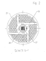
- the metering unit 23 consists essentially of a pump 24, for example may be formed as a screw pump, a forming wire 25, as a sieve tray serves, as well as a rotary knife 26.
- the rotary knife 26 is loosely on a drive shaft 27 and is by means of a spring 28 or the like against the forming wire 25th pressed.
- the one by the spring 28 applied pressure on the rotary blade 26 can also by other conventional means such as hydraulic or pneumatic cylinders are applied.
- a Shaft 29 mounted with mounted blades 30 is mounted below the forming wire 25, ie in the flow direction of the mud behind the forming wire 25 and in front of the inlet opening 12 for the mud in the drying chamber 17.
- the rotatably driven knife 30 is arranged above an inlet opening 31 for dry air.
- two agitators 32, 33 are arranged in the illustrated embodiment, arranged in the transport direction of the sludge in front of vertical partitions 34, 35 are.
- the dividing walls 34, 35 are arranged perpendicular to the fluidization sieve 16.
- TheInternbian the partitions 34, 35 is more than half the width dimension of the Drying chamber 17.
- a threshold 36 is provided, whose height is adjustable.
- the fluidization dryer 10 is an integral part of the device 37 for Drying of sludge according to FIG. 4. Immediately to the outlet opening 15 for the Dry air from the drying chamber is arranged a line system 38, the Return of the dry air is used. Through the conduit system 38, the device 37 designed as a closed system. Starting from the fluidization dryer 10 are located in the flow direction of the dry air means 39 for dedusting, means 40 for Dehumidify, a fan 41 for exhaust air, a shutter control 42, a fan 43 for supply air and a heat-air generator 44. In the area of the heat-generating air generator 44 a combustion chamber 45 is provided.
- a Auger 48 or the like for transporting the sludge through the device 47 arranged.
- the rotatably driven screw 48 is in its rotational speed variably adjustable.
- a Outlet opening for the sludge arranged In the transport direction at the end of the device 47 is a Outlet opening for the sludge arranged, which are passed into a container 49 can.
- the container 49 also serves to receive the filtered from the dry air Dust through the means 39 for dedusting the dry air.
- the device 47 discharged dry air is again by means of a line 50 the pipe system 38 supplied. On the input side, the device 47 has an inlet opening 51 for Dry air on.
- the dry air supplied to the device 47 is through the piping system 38 led to the device 47.
- the line system 38 shares in the transport direction behind the heat-air generator 44. Part of the dry air flow is passed to the device 47. The main part of the dry air becomes the air chamber of the fluidization dryer 10 passed. A third part of the dry air will be the Dosing unit 23 supplied.
- Another line 52 extends from the blind control 42 to the combustion chamber 45 of the heat generator 44th
- the means 39 for dedusting the discharged from the drying chamber 17 dry air contains dedusting modules, by means of which a very high dedusting degree of Dry air is achieved without reducing the moisture content.
- the means 40 for dehumidifying the already cleaned of the dust dry air contains a heat exchanger. For discharging the vapor condensate from the heat exchanger exists not shown condensate drain.
- the Heat-air generator 44 designed as a membrane heat-air generator.
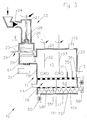
- the embodiment of the fluidization dryer 10 according to FIG. 3 essentially corresponds Parts of the embodiment of FIG. 1, so that the same parts for the same parts Reference numerals are used.
- the fluidization dryer differs 10 of FIG. 3 relative to that of FIG. 1 in that the supply air chamber 18th in turn divided into an upper chamber 53 and a lower chamber 54.
- the two Chambers 53 and 54 are separated by a sieve bottom 55.
- the entrance opening 14 for the dry air is in the region of the upper chamber 53 in the side wall 19 trained.
- Within the lower chamber 54 is a means of transport for the led from the drying chamber 17 via a conduit system 56 in the lower chamber Mud provided.
- the transport is in the illustrated embodiment as Screw conveyor 57 is formed.
- the screw conveyor 57 is rotatable and in terms of the rotational speed adjustable.
- the sieve bottom 55 has openings 58 on, in a region near the inlet opening 14 (not shown) flow flaps have, which open in the direction of the inlet opening 14 and in an in Flow direction rear portion of the dry air (not shown) have sheets, whose opening is remote from the inlet opening 14.
- the fluidization dryer 10 according to FIG. 3 is an essential part of the device 59 of FIG. 5.
- the device 59 of FIG. 5 is substantially identical to the device 37 of FIG. 4, but with the difference that from the drying chamber guided sludge via line 56 into the lower chamber 53 of the supply air chamber 18 is headed. The dried mud is then over a pipe 60 passed into the container 49.
- Another difference is that the piping system 38 in the flow direction behind the heat generator 44 is only divided into two, namely with a main line to the upper chamber 53 of the supply air chamber 18 and a another supply line to the dosing unit 23.
- FIG. 6 shows a device 65, which is essentially the device 59 corresponds to Figure 5, so that for the same parts the corresponding reference numerals are forgiven and a description is omitted.
- the Device 65 a heat pump system 66 on.
- the heat pump system 66 is suitably made of two heat exchangers, wherein a heat exchanger as Evaporator 67 and the other heat exchanger is designed as a capacitor 68.
- a pump 71 is provided for transporting a refrigerant.
- the flow direction of the Refrigerant is indicated in Figure 6 by arrows.
- a valve 72 is arranged in the 70th line.
- a refrigerant which serves as a heat carrier, water / steam is provided. But there are others too Usual refrigerant can be used.
- the evaporator 67 is in the exhaust air flow from the Fluidisationdrockner 10 in the region of the conduit system 38 in the transport direction of the Exhaust air flow between the means 39 for dedusting and the means 40 for Dehumidify arranged.
- the condenser 68 is in the region of the line system 38 between the fan 43 for the supply air and the heat generator 44 is provided.
- the heat pump system 66 can also be part of the device 37 according to FIG. 4.
- the mechanically dewatered to a moisture content of 65-90% sludge is conveyed by the screw pump 24 to the metering unit 23, which is also referred to as fluidization metering device.
- the sludge falls on the forming wire 25 and is uniformly pressed by the rotating rotary knife 26 through the openings of the forming wire 25.
- the predominantly paste-like material is transformed into thread-like, longer elastic fragments. These thread-like fragments are also called "noodles".
- the rotation of the rotary knife 26 ensures that the area of the forming wire 25 is permanently cleaned, so that blockages, in particular by fibrous and solid materials, are avoided.
- the thread-like fragments of the sludge come in free fall in a lower chamber 61 of the dosing unit 23.
- This lower chamber 61 is supplied via the inlet 31 through the heat generator 44 heated air, the air flow causes a uniform surface drying, especially the surface of the formed sludge ,
- the temperature of the air is preferably 130 to 150 ° C. Pre-drying prevents repeated aggregation of the formed sludge. In other words, the so-called glue phase of the sludge is avoided.
- the from the supply air chamber 18 in the drying chamber 17 flowing air stream relaxes while it flows upwards and points a speed at the height of the Fluidisationssiebes 16 two to four times is higher than the speed of flooding of the mud.
- supplied air flow is achieved on the one hand that supplied energy is, so that necessary for the evaporation of water from the mud heat energy is available.
- the air flow serves as a carrier for kinetic Energy with which the energy required for the fluidization of the sludge is supplied becomes.
- the air flow also serves as a carrier of the evaporated water, namely for discharging the water vapor from the drying chamber 17 through the outlet opening 15.
- the sludge is dried by exposure to the high temperature of the drying air. Due to the intensive mixing and high air speed of the fast energy exchange and the water outlet favors.
- the fluidized bed behaves like a boiling liquid, which tends to mirror balance.
- variable threshold 36 When discharging the mud from the drying chamber 17, the variable threshold 36 is used to determine the height of the Sludge layer in the drying chamber 17 and thus the residence time and the To regulate the degree of dryness.
- the height of the mud layer set at a level of about 30-150 mm above the surface of the fluidization sieve 16.
- other heights are conceivable in order to determine the length of stay of the To regulate sludge in the drying chamber 17.
- the sludge becomes after the discharge from the drying chamber 17 via the line 46 of the device 47 for post-drying supplied to the mud.
- the sludge becomes elevated temperature by dry air at a temperature of preferably about 130 to 150 ° C, which is supplied directly from the heat-air generator 44, retained and dried, to allow the migration of residual moisture from the granulated sludge.
- the device 47 has the screw 48 on mud mixing and air flow for steam removal to enable.
- the advantage of the system is that through the continuous Mixture the moisture transported by means of particle diffusion and / or capillary forces out becomes.
- the residence time in the device 47 can be controlled by the rotational speed the worm 48 influence.
- a setting of the residence time is also particularly desirable because of the removal of the osmotic bound and contained in plant and animal cells or in colloids To ensure moisture. Furthermore, it is also achieved by the post-drying the water connected by chemical bonds or coordination bonds to remove from the mud. By the multi-stage drying of the mud The final result is mud with a moisture content of about 1-15%. Furthermore, due to the long residence time of the sludge at elevated temperatures the final product hygienic. The dried mud is passed through a cell lock sealed sludge outlet nozzle (not shown) in the container 49th transported. The dry air flow from the device 47 is in the piping system 38 returned.
- the discharged from the drying chamber 17 dry air, which has a temperature of about 60-90 ° Celsius, through the conduit system 38 to the means 39 for dedusting fed and dedusted there, but without removing the exhaust air moisture.
- the from the drying chamber 17 escaping dry air is saturated with moisture and contaminated with dust and aerosols.
- the dedusted but still moist dry air is via the line system 38 the means 40 for dehumidifying fed.
- the air temperature is cooled down to about 40-70 ° Celsius and thereby achieves steam condensation.
- the process temperatures are corresponding adapted to the significant changes in the vapor content in the air at to guarantee small changes in temperature.
- the broth condensate from the heat exchanger is discharged to the outside.
- the broths will be while in the middle 40, which is designed as a heat exchanger or cooler, without condensed direct contact with the coolant.
- the contamination of the resulting Condensate is because of the solution used and the effective dedusting system very low.
- the dedusted and dehumidified dry air behind in the flow direction of the dry air the means 40 for dehumidifying a temperature of about 40-70 ° Celsius, is supplied via the line system 38 of the shutter controller 42.
- a minimal Proportion of cooled and dedusted dry air up to a maximum of 5% is temporarily passed directly into the combustion chamber 45 of the heat generator 44 and burned there. This is the harmlessness of gaseous organic Impurities ensured.
- the minimum proportion of to be delivered to the combustion chamber 45 Air is supplemented by fresh air.
- the dry air through the Ventilation supplied by means of the fan 43 to the heat-air generator 44.
- the fan 43 By using the fan 43, a low vacuum is built, the safety and user hygiene within the fluidization dryer 10.
- the dry air is returned to the required temperature increase from about 130-150 ° Celsius. To close the dry air circuit permit the use of the membrane heat generator is necessary to the Flue gas flow and dry air flow to separate.
- the method with the device 59 according to FIG. 5 proceeds in a very similar way.
- the sludge after exiting the drying chamber 17 directly to the bottom Chamber 54 of the supply air chamber 18 is supplied and subjected there to a post-drying.
- the sludge is conveyed through the device 47, wherein the transport speed can be regulated via the screw.
- the dry air for drying is fed through the conduit system 38 of the supply air chamber 18, wherein the dry air passes through the sieve bottom 55 into the lower chamber 54.
- the dried one Mud is supplied to the container 49 via the line 60.
- the exhaust air escapes through the sieve bottom 55 via the drying chamber 17 in the line system 38th
- the method with the device 65 according to FIG. 6 substantially expires the method with the device 59 according to FIG 5.
- the dry air or the exhaust air in a first step at least partially dehumidified, whereby the through the Dehumidification extracted Kondensations Keinenge before the heat generator 44 via the condenser 68 is fed into the conduit system 38 or for heating the Air within the line 38 in front of the heat generator 44 is used.
- the coolant circulates in the pipes 69,70 and is driven by the pump 71.
- the valve 72 can be the Control or control coolant flow.
- the exhaust air is after the evaporator 67 then further dehumidified by the means 40 in a further step. By the at least partial dehumidification of the dry air through the evaporator 67 can the performance of the agent 40 can be reduced.
Landscapes
- Drying Of Solid Materials (AREA)
- Treatment Of Sludge (AREA)
Claims (18)
- Procédé de séchage de boue, en particulier de boue d'égout, comportant les étapes consistant à :a) déshydrater mécaniquement la boue jusqu'à atteindre une teneur en humidité de 90 à 65 % environ,b) amener la boue dans un sécheur à lit fluidisé (10),c) sécher la boue dans un espace de séchage (11) du sécheur à lit fluidisé (10) avec de l'air de séchage,d) évacuer de l'espace de séchage la boue séchée à une teneur en humidité de 30 à 15% environ d'une part et l'air de séchage désormais humide et contenant de la poussière d'autre part,e) l'air de séchage évacué de l'espace de séchage (11) étant dépoussiéré, déshumidifié puis ramené à l'espace de séchage (11) après réchauffement dans un circuit fermé,
caractérisé en ce quef) la boue est façonnée avant l'entrée dans l'espace de séchage (11),g) la boue façonnée est séchée au moins en surface en chute libre dans un flux opposé d'air de séchage,h) est pulvérisée, eti) est amenée ensuite à l'espace de séchage. - Procédé selon la revendication 1, caractérisé en ce que la boue est maintenue en suspension pendant le séchage dans une chambre de séchage (17) de l'espace de séchage (11).
- Procédé selon la revendication 1 ou 2, caractérisé en ce que la vitesse de l'air de séchage au niveau d'un fond perforé (16) à l'intérieur de l'espace de séchage (11) est environ deux à quatre fois supérieure à la vitesse de suspension de la boue.
- Procédé selon l'une des revendications 1 à 3, caractérisé en ce que la chaleur dégagée par la déshumidification de l'air de séchage en aval du sécheur à lit fluidisé (10), par référence au sens de transport, est utilisée pour chauffer l'air de séchage en amont du sécheur à lit fluidisé (10).
- Procédé selon l'une des revendications 2 à 4, caractérisé en ce que la boue évacuée de la chambre de séchage (17) est amenée à un dispositif de séchage final (47) dans lequel elle est soumise à de l'air de séchage provenant du circuit fermé pour être séchée jusqu'à une teneur en humidité de 15 à 1 % environ.
- Procédé selon la revendication 5, caractérisé en ce que le temps de séjour de la boue dans l'espace de séchage (11) et/ou le dispositif de séchage final (47) est régulé.
- Dispositif de séchage de boue, en particulier de boue d'égout, essentiellement constitué d'un sécheur à lit fluidisé (10) comportant un espace de séchage (11) doté d'une ouverture d'entrée (12) et d'une ouverture de sortie (13) destinées à la boue, d'une ouverture d'entrée (14) et d'une ouverture de sortie (15) destinées à l'air de séchage, et d'un fond perforé (16) s'étendant horizontalement et qui divise l'espace de séchage (11) en une chambre de séchage (17) et une chambre d'amenée d'air (18), le sécheur à lit fluidisé (10) étant conformé en système fermé au moyen d'un système de conduites (38) dans lequel un moyen de dépoussiérage (39), un moyen de déshumidification (40), au moins un ventilateur (41, 42) destiné à amener et évacuer de l'air, au moins un dispositif de régulation à lamelles orientables (42) et un générateur d'air chaud (44) sont placés en aval du sécheur à lit fluidisé (10) par référence au sens de transport, caractérisé en ce qu'une unité de dosage (23), conformée en chargeur de boue, est placée au niveau de l'ouverture d'entrée (12) destinée à la boue et est constituée d'un boítier comportant une pompe (24), d'un tamis profilé (25) servant de fond perforé et d'un doseur rotatif (26) qui peut être poussé contre le tamis profilé (25), en ce qu'un moyen de pulvérisation de la boue est placée en aval du tamis profilé (25) par référence au sens d'écoulement de la boue, et en ce qu'une ouverture d'entrée (31) destinée à l'air de séchage est prévue dans l'unité de dosage (23).
- Dispositif selon la revendication 7, caractérisé en ce qu'un dispositif (47) destiné au séchage final de la boue est monté en aval du sécheur à lit fluidisé (10).
- Dispositif selon la revendication 8, caractérisé en ce que le dispositif de séchage final (47) fait partie intégrante du sécheur à lit fluidisé (10).
- Dispositif selon la revendication 8 ou 9, caractérisé en ce que le dispositif de séchage final (47) est placé à l'intérieur de la chambre d'amenée d'air (18).
- Dispositif selon l'une des revendications 7 à 10, caractérisé en ce que au moins un agitateur (32, 33) est placé à l'intérieur de la chambre de séchage (17).
- Dispositif selon l'une des revendications 7 à 11, caractérisé en ce que au moins une paroi de séparation (34, 35), qui est orientée perpendiculairement au fond perforé (16) et dont la longueur est supérieure à la moitié de la largeur de la chambre de séchage (17), est placée à l'intérieur de la chambre de séchage (17).
- Dispositif selon l'une des revendications 7 à 12, caractérisé en ce qu'il est prévu un seuil réglable (36) au niveau de l'ouverture de sortie (13) destinée à la sortie de la boue de la chambre de séchage (17).
- Dispositif selon l'une des revendications 7 à 13, caractérisé en ce qu'une installation de pompage de chaleur (66) est placée dans le circuit du système de conduites (38).
- Dispositif selon la revendication 14, caractérisé en ce que l'installation de pompage chaleur (66) comporte un évaporateur (67), un condenseur (68), des conduites (69, 70), une pompe (71) et un clapet (72).
- Dispositif selon la revendication 15, caractérisé en ce que l'évaporateur (67) est placé entre le moyen de dépoussiérage (39) et le moyen de déshumidification (40) et le condenseur (68) est placé entre le ventilateur (43) et le générateur d'air chaud (44).
- Dispositif selon l'une des revendications 7 à 16, caractérisé en ce qu'il est prévu une chambre de combustion (45) au niveau du générateur d'air chaud (44).
- Dispositif selon l'une des revendications 8 à 17, caractérisé en ce que le dispositif de séchage final (47) fait partie intégrante du système fermé.
Priority Applications (1)
| Application Number | Priority Date | Filing Date | Title |
|---|---|---|---|
| EP02790670A EP1453763B1 (fr) | 2001-12-13 | 2002-12-10 | Procede et dispositif de sechage de boues, en particulier de boues d'eaux usees |
Applications Claiming Priority (8)
| Application Number | Priority Date | Filing Date | Title |
|---|---|---|---|
| PL11281801 | 2001-12-13 | ||
| PL11281801 | 2001-12-13 | ||
| PL351295A PL200587B1 (pl) | 2001-12-20 | 2001-12-20 | Sposób ciągłego suszenia osadów ściekowych |
| PL35129501 | 2001-12-20 | ||
| EP02090176 | 2002-05-22 | ||
| EP02090176A EP1319632A1 (fr) | 2001-12-13 | 2002-05-22 | Procédé et dispositif pour le séchage de boues, en particulier de boues d'épuration |
| EP02790670A EP1453763B1 (fr) | 2001-12-13 | 2002-12-10 | Procede et dispositif de sechage de boues, en particulier de boues d'eaux usees |
| PCT/IB2002/005767 WO2003050046A1 (fr) | 2001-12-13 | 2002-12-10 | Procede et dispositif de sechage de boues, en particulier de boues d'eaux usees |
Publications (2)
| Publication Number | Publication Date |
|---|---|
| EP1453763A2 EP1453763A2 (fr) | 2004-09-08 |
| EP1453763B1 true EP1453763B1 (fr) | 2005-11-30 |
Family
ID=56290366
Family Applications (1)
| Application Number | Title | Priority Date | Filing Date |
|---|---|---|---|
| EP02790670A Expired - Lifetime EP1453763B1 (fr) | 2001-12-13 | 2002-12-10 | Procede et dispositif de sechage de boues, en particulier de boues d'eaux usees |
Country Status (3)
| Country | Link |
|---|---|
| EP (1) | EP1453763B1 (fr) |
| AT (1) | ATE311350T1 (fr) |
| AU (1) | AU2002366593A1 (fr) |
-
2002
- 2002-12-10 EP EP02790670A patent/EP1453763B1/fr not_active Expired - Lifetime
- 2002-12-10 AU AU2002366593A patent/AU2002366593A1/en not_active Abandoned
- 2002-12-10 AT AT02790670T patent/ATE311350T1/de active
Also Published As
| Publication number | Publication date |
|---|---|
| EP1453763A2 (fr) | 2004-09-08 |
| ATE311350T1 (de) | 2005-12-15 |
| AU2002366593A1 (en) | 2003-06-23 |
Similar Documents
| Publication | Publication Date | Title |
|---|---|---|
| EP3111148B1 (fr) | Procédé pour le séchage de matériau en vrac | |
| AT412277B (de) | Verfahren und vorrichtung zum kontinuierlichen trocknen von gut, insbesondere klärschlamm | |
| EP0873286A1 (fr) | Procede et dispositif de traitement aerobie de substances organiques | |
| DE3005291A1 (de) | Verfahren und vorrichtung zur konditionierung von luft mittels trocknung durch ein sorbierendes material | |
| WO2003050046A1 (fr) | Procede et dispositif de sechage de boues, en particulier de boues d'eaux usees | |
| DE4235422A1 (de) | Verfahren zum Trocknen von vorzugsweise in pelletierter Form vorliegenden pastösen Material, insbesondere Klärschlamm und Vorrichtung zur Durchführung des Verfahrens | |
| DE69220246T2 (de) | Umweltfreundlicher und energiesparender stall für tiere, zum beispiel für schweine | |
| EP2410875A1 (fr) | Procédé et dispositif pour le séchage de produits | |
| AT510487A1 (de) | Trocknungsverfahren und trocknungssystem | |
| DE102008046299B4 (de) | Verfahren und Vorrichtung zum Trocknen von Biomasse | |
| DE102015222938A1 (de) | Vorrichtung zum Trocknen von Pulver und Fertigungssystem | |
| DE2527195A1 (de) | Anlage zur aufbereitung von muell und/oder eingedicktem schlamm | |
| EP0458221B1 (fr) | Procédé de séchage de boues de décantation | |
| EP0356388A2 (fr) | Procédé et dispositif pour déshydrater des masses aqueuses | |
| EP0835226B1 (fr) | Procede et dispositif de sechage en continu de boues contenant des proteines | |
| DE69733021T2 (de) | Anlage zur behandlung biologischer abfälle | |
| DE68912430T2 (de) | Verfahren und Vorrichtung zur Trocknung von organischen Abfällen. | |
| EP1453763B1 (fr) | Procede et dispositif de sechage de boues, en particulier de boues d'eaux usees | |
| CH645333A5 (en) | Moist composting process for organic waste materials, for example sewage sludge, and apparatus for carrying out the process | |
| DE351216C (de) | Verfahren und Vorrichtung zur Trennung fluessiger von festen Stoffen | |
| DE69800889T2 (de) | Verfahren zum betreiben einer trocknungsvorrichtung, sowie eine vorrichtung zur durchführung dieses verfahrens | |
| DE102006054566B3 (de) | Trocknungsanlage-Trommelmischer für Klärschlamm | |
| EP4399465A1 (fr) | Unité de séchage mobile et système de séchage | |
| DE102004036081A1 (de) | Neues Trocknungskonzept (Trocknungsanlage) für Klärschlamm | |
| EP3640572A2 (fr) | Procédé et installation de séchage pour bois humide et analogue ayant une qualité de gaz d'échappement améliorée |
Legal Events
| Date | Code | Title | Description |
|---|---|---|---|
| PUAI | Public reference made under article 153(3) epc to a published international application that has entered the european phase |
Free format text: ORIGINAL CODE: 0009012 |
|
| 17P | Request for examination filed |
Effective date: 20040624 |
|
| AK | Designated contracting states |
Kind code of ref document: A2 Designated state(s): AT BE BG CH CY CZ DE DK EE ES FI FR GB GR IE IT LI LU MC NL PT SE SI SK TR |
|
| AX | Request for extension of the european patent |
Extension state: AL LT LV MK RO |
|
| GRAP | Despatch of communication of intention to grant a patent |
Free format text: ORIGINAL CODE: EPIDOSNIGR1 |
|
| GRAS | Grant fee paid |
Free format text: ORIGINAL CODE: EPIDOSNIGR3 |
|
| GRAA | (expected) grant |
Free format text: ORIGINAL CODE: 0009210 |
|
| AK | Designated contracting states |
Kind code of ref document: B1 Designated state(s): AT BE BG CH CY CZ DE DK EE ES FI FR GB GR IE IT LI LU MC NL PT SE SI SK TR |
|
| PG25 | Lapsed in a contracting state [announced via postgrant information from national office to epo] |
Ref country code: GB Free format text: LAPSE BECAUSE OF FAILURE TO SUBMIT A TRANSLATION OF THE DESCRIPTION OR TO PAY THE FEE WITHIN THE PRESCRIBED TIME-LIMIT Effective date: 20051130 Ref country code: CZ Free format text: LAPSE BECAUSE OF FAILURE TO SUBMIT A TRANSLATION OF THE DESCRIPTION OR TO PAY THE FEE WITHIN THE PRESCRIBED TIME-LIMIT Effective date: 20051130 Ref country code: TR Free format text: LAPSE BECAUSE OF FAILURE TO SUBMIT A TRANSLATION OF THE DESCRIPTION OR TO PAY THE FEE WITHIN THE PRESCRIBED TIME-LIMIT Effective date: 20051130 Ref country code: NL Free format text: LAPSE BECAUSE OF FAILURE TO SUBMIT A TRANSLATION OF THE DESCRIPTION OR TO PAY THE FEE WITHIN THE PRESCRIBED TIME-LIMIT Effective date: 20051130 Ref country code: IE Free format text: LAPSE BECAUSE OF FAILURE TO SUBMIT A TRANSLATION OF THE DESCRIPTION OR TO PAY THE FEE WITHIN THE PRESCRIBED TIME-LIMIT Effective date: 20051130 Ref country code: FI Free format text: LAPSE BECAUSE OF FAILURE TO SUBMIT A TRANSLATION OF THE DESCRIPTION OR TO PAY THE FEE WITHIN THE PRESCRIBED TIME-LIMIT Effective date: 20051130 Ref country code: SK Free format text: LAPSE BECAUSE OF FAILURE TO SUBMIT A TRANSLATION OF THE DESCRIPTION OR TO PAY THE FEE WITHIN THE PRESCRIBED TIME-LIMIT Effective date: 20051130 Ref country code: EE Free format text: LAPSE BECAUSE OF FAILURE TO SUBMIT A TRANSLATION OF THE DESCRIPTION OR TO PAY THE FEE WITHIN THE PRESCRIBED TIME-LIMIT Effective date: 20051130 Ref country code: SI Free format text: LAPSE BECAUSE OF FAILURE TO SUBMIT A TRANSLATION OF THE DESCRIPTION OR TO PAY THE FEE WITHIN THE PRESCRIBED TIME-LIMIT Effective date: 20051130 Ref country code: IT Free format text: LAPSE BECAUSE OF FAILURE TO SUBMIT A TRANSLATION OF THE DESCRIPTION OR TO PAY THE FEE WITHIN THE PRESCRIBED TIME-LIMIT;WARNING: LAPSES OF ITALIAN PATENTS WITH EFFECTIVE DATE BEFORE 2007 MAY HAVE OCCURRED AT ANY TIME BEFORE 2007. THE CORRECT EFFECTIVE DATE MAY BE DIFFERENT FROM THE ONE RECORDED. Effective date: 20051130 |
|
| REG | Reference to a national code |
Ref country code: CH Ref legal event code: EP Ref country code: GB Ref legal event code: FG4D Free format text: NOT ENGLISH |
|
| PG25 | Lapsed in a contracting state [announced via postgrant information from national office to epo] |
Ref country code: CY Free format text: LAPSE BECAUSE OF FAILURE TO SUBMIT A TRANSLATION OF THE DESCRIPTION OR TO PAY THE FEE WITHIN THE PRESCRIBED TIME-LIMIT Effective date: 20051210 |
|
| REG | Reference to a national code |
Ref country code: IE Ref legal event code: FG4D Free format text: LANGUAGE OF EP DOCUMENT: GERMAN |
|
| PG25 | Lapsed in a contracting state [announced via postgrant information from national office to epo] |
Ref country code: MC Free format text: LAPSE BECAUSE OF NON-PAYMENT OF DUE FEES Effective date: 20051231 Ref country code: BE Free format text: LAPSE BECAUSE OF NON-PAYMENT OF DUE FEES Effective date: 20051231 |
|
| REF | Corresponds to: |
Ref document number: 50205141 Country of ref document: DE Date of ref document: 20060105 Kind code of ref document: P |
|
| PG25 | Lapsed in a contracting state [announced via postgrant information from national office to epo] |
Ref country code: LU Free format text: LAPSE BECAUSE OF NON-PAYMENT OF DUE FEES Effective date: 20060130 |
|
| PG25 | Lapsed in a contracting state [announced via postgrant information from national office to epo] |
Ref country code: SE Free format text: LAPSE BECAUSE OF FAILURE TO SUBMIT A TRANSLATION OF THE DESCRIPTION OR TO PAY THE FEE WITHIN THE PRESCRIBED TIME-LIMIT Effective date: 20060228 Ref country code: BG Free format text: LAPSE BECAUSE OF FAILURE TO SUBMIT A TRANSLATION OF THE DESCRIPTION OR TO PAY THE FEE WITHIN THE PRESCRIBED TIME-LIMIT Effective date: 20060228 Ref country code: GR Free format text: LAPSE BECAUSE OF FAILURE TO SUBMIT A TRANSLATION OF THE DESCRIPTION OR TO PAY THE FEE WITHIN THE PRESCRIBED TIME-LIMIT Effective date: 20060228 Ref country code: DK Free format text: LAPSE BECAUSE OF FAILURE TO SUBMIT A TRANSLATION OF THE DESCRIPTION OR TO PAY THE FEE WITHIN THE PRESCRIBED TIME-LIMIT Effective date: 20060228 |
|
| REG | Reference to a national code |
Ref country code: CH Ref legal event code: NV Representative=s name: E. BLUM & CO. PATENTANWAELTE |
|
| PG25 | Lapsed in a contracting state [announced via postgrant information from national office to epo] |
Ref country code: ES Free format text: LAPSE BECAUSE OF FAILURE TO SUBMIT A TRANSLATION OF THE DESCRIPTION OR TO PAY THE FEE WITHIN THE PRESCRIBED TIME-LIMIT Effective date: 20060313 |
|
| PG25 | Lapsed in a contracting state [announced via postgrant information from national office to epo] |
Ref country code: PT Free format text: LAPSE BECAUSE OF FAILURE TO SUBMIT A TRANSLATION OF THE DESCRIPTION OR TO PAY THE FEE WITHIN THE PRESCRIBED TIME-LIMIT Effective date: 20060502 |
|
| NLV1 | Nl: lapsed or annulled due to failure to fulfill the requirements of art. 29p and 29m of the patents act | ||
| GBV | Gb: ep patent (uk) treated as always having been void in accordance with gb section 77(7)/1977 [no translation filed] |
Effective date: 20051130 |
|
| REG | Reference to a national code |
Ref country code: IE Ref legal event code: FD4D |
|
| PLBE | No opposition filed within time limit |
Free format text: ORIGINAL CODE: 0009261 |
|
| STAA | Information on the status of an ep patent application or granted ep patent |
Free format text: STATUS: NO OPPOSITION FILED WITHIN TIME LIMIT |
|
| 26N | No opposition filed |
Effective date: 20060831 |
|
| EN | Fr: translation not filed | ||
| REG | Reference to a national code |
Ref country code: CH Ref legal event code: PFA Owner name: KLIMAPOL SP.Z O.O.J.V. Free format text: KLIMAPOL SP.Z O.O.J.V.#UL. DABROWICA 127 C#PL-21-002 JASTKOW (PL) -TRANSFER TO- KLIMAPOL SP.Z O.O.J.V.#UL. DABROWICA 127 C#PL-21-002 JASTKOW (PL) |
|
| BERE | Be: lapsed |
Owner name: KLIMAPOL SP.Z O.O.J.V. Effective date: 20051231 |
|
| PG25 | Lapsed in a contracting state [announced via postgrant information from national office to epo] |
Ref country code: FR Free format text: LAPSE BECAUSE OF FAILURE TO SUBMIT A TRANSLATION OF THE DESCRIPTION OR TO PAY THE FEE WITHIN THE PRESCRIBED TIME-LIMIT Effective date: 20070119 |
|
| PG25 | Lapsed in a contracting state [announced via postgrant information from national office to epo] |
Ref country code: FR Free format text: LAPSE BECAUSE OF FAILURE TO SUBMIT A TRANSLATION OF THE DESCRIPTION OR TO PAY THE FEE WITHIN THE PRESCRIBED TIME-LIMIT Effective date: 20051231 |
|
| PG25 | Lapsed in a contracting state [announced via postgrant information from national office to epo] |
Ref country code: FR Free format text: LAPSE BECAUSE OF FAILURE TO SUBMIT A TRANSLATION OF THE DESCRIPTION OR TO PAY THE FEE WITHIN THE PRESCRIBED TIME-LIMIT Effective date: 20051130 |
|
| PGFP | Annual fee paid to national office [announced via postgrant information from national office to epo] |
Ref country code: AT Payment date: 20101125 Year of fee payment: 9 |
|
| PGFP | Annual fee paid to national office [announced via postgrant information from national office to epo] |
Ref country code: CH Payment date: 20101104 Year of fee payment: 9 |
|
| PGFP | Annual fee paid to national office [announced via postgrant information from national office to epo] |
Ref country code: DE Payment date: 20101229 Year of fee payment: 9 |
|
| REG | Reference to a national code |
Ref country code: CH Ref legal event code: PL |
|
| REG | Reference to a national code |
Ref country code: DE Ref legal event code: R119 Ref document number: 50205141 Country of ref document: DE Effective date: 20120703 |
|
| PG25 | Lapsed in a contracting state [announced via postgrant information from national office to epo] |
Ref country code: LI Free format text: LAPSE BECAUSE OF NON-PAYMENT OF DUE FEES Effective date: 20111231 Ref country code: CH Free format text: LAPSE BECAUSE OF NON-PAYMENT OF DUE FEES Effective date: 20111231 Ref country code: DE Free format text: LAPSE BECAUSE OF NON-PAYMENT OF DUE FEES Effective date: 20120703 |
|
| REG | Reference to a national code |
Ref country code: AT Ref legal event code: MM01 Ref document number: 311350 Country of ref document: AT Kind code of ref document: T Effective date: 20111210 |
|
| PG25 | Lapsed in a contracting state [announced via postgrant information from national office to epo] |
Ref country code: AT Free format text: LAPSE BECAUSE OF NON-PAYMENT OF DUE FEES Effective date: 20111210 |