EP1454568A2 - Chaise, notamment chaise de bureau - Google Patents
Chaise, notamment chaise de bureau Download PDFInfo
- Publication number
- EP1454568A2 EP1454568A2 EP04004811A EP04004811A EP1454568A2 EP 1454568 A2 EP1454568 A2 EP 1454568A2 EP 04004811 A EP04004811 A EP 04004811A EP 04004811 A EP04004811 A EP 04004811A EP 1454568 A2 EP1454568 A2 EP 1454568A2
- Authority
- EP
- European Patent Office
- Prior art keywords
- seat support
- chair
- support part
- pivot axis
- bolt
- Prior art date
- Legal status (The legal status is an assumption and is not a legal conclusion. Google has not performed a legal analysis and makes no representation as to the accuracy of the status listed.)
- Granted
Links
Images


Classifications
-
- A—HUMAN NECESSITIES
- A47—FURNITURE; DOMESTIC ARTICLES OR APPLIANCES; COFFEE MILLS; SPICE MILLS; SUCTION CLEANERS IN GENERAL
- A47C—CHAIRS; SOFAS; BEDS
- A47C1/00—Chairs adapted for special purposes
- A47C1/02—Reclining or easy chairs
- A47C1/031—Reclining or easy chairs having coupled concurrently adjustable supporting parts
- A47C1/032—Reclining or easy chairs having coupled concurrently adjustable supporting parts the parts being movably-coupled seat and back-rest
- A47C1/03255—Reclining or easy chairs having coupled concurrently adjustable supporting parts the parts being movably-coupled seat and back-rest with a central column, e.g. rocking office chairs
-
- A—HUMAN NECESSITIES
- A47—FURNITURE; DOMESTIC ARTICLES OR APPLIANCES; COFFEE MILLS; SPICE MILLS; SUCTION CLEANERS IN GENERAL
- A47C—CHAIRS; SOFAS; BEDS
- A47C1/00—Chairs adapted for special purposes
- A47C1/02—Reclining or easy chairs
- A47C1/031—Reclining or easy chairs having coupled concurrently adjustable supporting parts
- A47C1/032—Reclining or easy chairs having coupled concurrently adjustable supporting parts the parts being movably-coupled seat and back-rest
- A47C1/03205—Reclining or easy chairs having coupled concurrently adjustable supporting parts the parts being movably-coupled seat and back-rest having adjustable and lockable inclination
- A47C1/03233—Reclining or easy chairs having coupled concurrently adjustable supporting parts the parts being movably-coupled seat and back-rest having adjustable and lockable inclination by means of a rack-and-pinion or like gearing mechanism
-
- A—HUMAN NECESSITIES
- A47—FURNITURE; DOMESTIC ARTICLES OR APPLIANCES; COFFEE MILLS; SPICE MILLS; SUCTION CLEANERS IN GENERAL
- A47C—CHAIRS; SOFAS; BEDS
- A47C1/00—Chairs adapted for special purposes
- A47C1/02—Reclining or easy chairs
- A47C1/031—Reclining or easy chairs having coupled concurrently adjustable supporting parts
- A47C1/032—Reclining or easy chairs having coupled concurrently adjustable supporting parts the parts being movably-coupled seat and back-rest
- A47C1/03205—Reclining or easy chairs having coupled concurrently adjustable supporting parts the parts being movably-coupled seat and back-rest having adjustable and lockable inclination
- A47C1/03238—Reclining or easy chairs having coupled concurrently adjustable supporting parts the parts being movably-coupled seat and back-rest having adjustable and lockable inclination by means of peg-and-notch or pawl-and-ratchet mechanism
-
- A—HUMAN NECESSITIES
- A47—FURNITURE; DOMESTIC ARTICLES OR APPLIANCES; COFFEE MILLS; SPICE MILLS; SUCTION CLEANERS IN GENERAL
- A47C—CHAIRS; SOFAS; BEDS
- A47C1/00—Chairs adapted for special purposes
- A47C1/02—Reclining or easy chairs
- A47C1/031—Reclining or easy chairs having coupled concurrently adjustable supporting parts
- A47C1/032—Reclining or easy chairs having coupled concurrently adjustable supporting parts the parts being movably-coupled seat and back-rest
- A47C1/03261—Reclining or easy chairs having coupled concurrently adjustable supporting parts the parts being movably-coupled seat and back-rest characterised by elastic means
- A47C1/03266—Reclining or easy chairs having coupled concurrently adjustable supporting parts the parts being movably-coupled seat and back-rest characterised by elastic means with adjustable elasticity
-
- A—HUMAN NECESSITIES
- A47—FURNITURE; DOMESTIC ARTICLES OR APPLIANCES; COFFEE MILLS; SPICE MILLS; SUCTION CLEANERS IN GENERAL
- A47C—CHAIRS; SOFAS; BEDS
- A47C1/00—Chairs adapted for special purposes
- A47C1/02—Reclining or easy chairs
- A47C1/031—Reclining or easy chairs having coupled concurrently adjustable supporting parts
- A47C1/032—Reclining or easy chairs having coupled concurrently adjustable supporting parts the parts being movably-coupled seat and back-rest
- A47C1/03261—Reclining or easy chairs having coupled concurrently adjustable supporting parts the parts being movably-coupled seat and back-rest characterised by elastic means
- A47C1/03272—Reclining or easy chairs having coupled concurrently adjustable supporting parts the parts being movably-coupled seat and back-rest characterised by elastic means with coil springs
Definitions
- the invention relates to a chair, in particular an office chair, after Preamble of claim 1.
- Such a chair is known from DE 43 24 545 A1.
- a so-called synchronous mechanism at the backrest and seat in a certain predetermined ratio to be pivoted simultaneously.
- a power storage in the form of a helical compression spring arranged, by means of between the front seat support part and the rear seat support member is generated a force which the backrest in its front end position and the rear area of the seat pushes in its upper position.
- a so-called seesaw mechanism given that is, the user can against the restoring force of the backrest bobbing with your back.
- the synchronous mechanism can be locked so that there is no relative movement between the seat support parts can be done more.
- a catch or locking the synchronous mechanism takes place in situations in which the user does not want mobility of the backrest. If the locking is done in an upright position of the backrest, the resulting seating position can be adjusted by the user with the Time to be uncomfortable.
- the invention is therefore based on the object, a better to the needs the user adapted locking device at a To create chair of the type mentioned.
- the locking device rather, provides a plurality of discrete locking positions the seat support parts ready for each other. It is therefore possible the Synchronous mechanism if required in a relatively upright or in one compared to lock inclined position of the backrest. Of course, you can also have more than two locking positions pretend.
- a stepless specification of locking positions by appropriate design of the locking device, for example, by a corresponding clamping mechanism, possible.
- a locking device according to claim 2 can be constructive with realize little effort, the locking device in the single discrete locking positions also larger load forces can withstand. As a rule, there are some locking positions, For example, four locking positions, sufficient.
- a locking device according to claim 3 is structurally simple and still safe.
- the locking device according to claim 4 ensured that the bolt and the counter body in a change of Relative positions of the seat support parts before locking their distance not significantly change each other, so that the stroke of the locking movement from the predetermined relative position between the seat support parts is essentially independent. This increases the ease of use of Locking device.
- a locking device In a locking device according to claim 5 is a specific Relative position between bar and counter-body of a relative position clearly assigned between the two seat support parts. This increases the Operating safety of the locking device.
- the pivot axis between the components of the locking device, ie the counter body and the bolt, may, but need not, with the pivot axis between the two seat support parts coincide.
- a coupling element can be a Translation between the relative pivoting of the components of the Locking device on the one hand and the seat support parts on the other pretend. Even with relatively far apart arranged Locking positions, as far as the locking device, can in this way finely graduated locking positions, what the Wegturimaschine anxx, realized.
- Fig. 1 shows an office chair with a chair frame 1. This is with a Pedestal 2 provided, which is about rollers 3 with respect to the ground supported. On the pedestal 2 is a height-adjustable chair column. 4 attached, at whose upper end a seat support 5 is attached. The latter is designed in two parts; he has a front seat support part 6, the on the chair column 4 is fixed, and a rear seat support part 7, the above the chair column 4 by means of a rotatable about a pivot axis 8 Swivel joint is articulated on the front seat support part 6.
- a support tube 9 is fixed, which is parallel to the pivot axis 8 extends. On this support tube 9 is based Seat 10 shortly behind its leading edge 11 from.
- the support tube 9 therefore represents a front support portion for the seat 10.
- the seat 10 is supported in its rear region on a support shaft 12 from the rear seat support part 7 is stored.
- the support shaft 12 therefore provides a rear support portion for the seat 10.
- At the rear seat support part 7 is still arranged a seat tilt adjustment 13.
- a backrest height adjustment device 16 is provided.
- the described embodiment of the seat support 5 with the arrangement of Seat 10 and the backrest 15 forms a so-called synchronous mechanism.
- a total provided with 17 designated force variation device that still will be explained in detail.
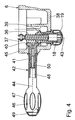
- Part of the force changing device 17 is a over the front seat support member 6 downwardly projecting adjusting nut 18, of which in Fig. 1, a freely rotatable cap 19 is visible.
- the chair column 4 has the height adjustment of the seat support 5 with the seat 10 and the backrest 15 a known length-adjustable gas spring 21st on, which is shown in Fig. 3 in plan view.
- the gas spring 21 is in a Cone formed clamping device 22 of the front seat support part. 6 held clamped. From the gas spring 21 projects upwards a valve actuating pin 23 out, when it is inserted into the gas spring 21 a there existing valve is opened, causing length adjustments of the gas spring 21 become possible.
- Such gas springs are for example in the DE 18 12 282 C2 (corresponding to US Pat. No. 3,656,593).
- valve operating lever 24 To actuate the valve actuating pin 23 is a two-armed Valve operating lever 24 is provided, which pivotally against the Swivel axis 8 is supported, as described for example in DE 43 24 545 A1 is.
- a first lever arm 25 of the valve operating lever 24 is located against the valve actuating pin 23, while the second lever arm 26th be actuated by a known from DE 43 24 545 A 1 lever mechanism can.
- a pivoting of the rear seat support part 7 relative to the front Seat support part 6 of the synchronous mechanism counteracts an energy storage 27, which is in the illustrated embodiment, a biased Screw compression spring 28 is.
- a biased Screw compression spring 28 is.
- the energy storage 27th a helical compression spring 28 passing through the guide rod 30.
- the compression coil spring 28 is supported against a shoe 31 of the force changing device 17 from.
- the sliding shoe 31 in turn abuts against a sliding surface 32, which at a first, short lever arm 33 of the rear seat support part 7 is formed.
- the lever arm 33 is integrally formed with the rear seat support member 7 and extends from the pivot axis 8 from substantially downwards.
- Geometric In this respect, the rear seat support part 7 is designed as an angle lever.
- On the guide rod 30 of the slide shoe 31 along the helical compression spring 28 movable. At one of the abutment 29 opposite Adjustment section 34 of the guide rod 30 engages the force changing device 17 on. A adjoining the adjusting portion 34 connecting portion 35 of the guide rod 30 passes through the first lever arm 33 of the rear seat support member 7.
- the screw compression spring 28 penetrating portion of the guide rod 30 Opposite the screw compression spring 28 penetrating portion of the guide rod 30 is the Connecting portion 35 toward the rear seat support member 7 angled.
- the adjusting portion 34 of the guide rod 30 is therefore on the bent back seat support part 7 to and the seat support 5 adjacent arranged.
- Part of the force changing device 17 is an adjusting screw 36, the on the adjusting portion 34 of the guide rod 30 via a pivot joint with Swivel axis 37 is pivotally articulated.
- the distance between the pivot axis 8 between the seat support parts 6, 7 on the one hand and the central axis of the helical compression spring 28 on the other is designated in Fig. 5 with a.
- the adjusting screw 36 engages in the adjusting nut 18, which in a lower Wall 38 of the front seat support member 6 rotatably, but in the direction of the screw 36 is mounted immovably.
- the adjusting nut 18 On the cap 19 opposite End, the adjusting nut 18 has a straight toothed conical section 39 on. In the sprocket of this engages a likewise straight toothed Cone portion 40 of an end portion 41 of an actuating rotary handle 42 on.
- the two cone sections 39, 40 thus form a straight-toothed Bevel gear.
- a rotation axis 43 of the adjusting screw 36 and an axis of rotation 44 of the actuating rotary handle 42 are not aligned with each other, but intersect and close a right one with each other Angle.
- the end portion 41 is in a side wall 45 of the front Seat support part 6 rotatably, but axially to the axis of rotation 44 of the actuating rotary handle 42 immovably stored.
- the free end of the actuating rotary handle 42 is as an oval handle 46th formed with recessed grips 47.
- the handle 46 has a central bore 48, which at the free end of the handle 46 by a depressed Cap 49 is closed. Introduced into the hole is a Connecting screw 50, which the handle 46 at the end portion 41 of Actuator rotary handle 42 holds.
- the sliding surface 32 at least approximately a circular arc section lies whose center above the axis the pivot joint of the abutment 29 is formed, changes at a rotation of the actuating rotary handle 42 a distance b between the pivot axis of the abutment 29 and the penetration of the axis of the energy storage 27 by the sliding surface 32 only slightly. Therefore changes in such adjustments, the bias of the coil compression spring 28 practically not.
- the sliding surface 32 formed by the abutment 29 Swivel joint is achieved that on the screw 36 is always a transmitted by the compression coil spring 28 mediated tensile force. This leads to to that the set screw 36 in the adjusting nut 18 always defined in such a way is guided, that in Fig. 5 overhead thread flanks of the thread the adjusting screw 36 to the corresponding thread flanks of the internal thread the adjusting nut 18 abut.
- the of the helical compression spring 28 on the first lever arm 33 of the rear Seat support part 7 acting force is therefore not changed; it will merely by changing the distance a between the axis of Force accumulator 27 and the pivot axis 8 of the effective lever arm, the Overall, that is from the helical compression spring 28 on the rear Seat support part 7 and thus on the seat 10 and the backrest 15 acting Torque, changed.
- This torque becomes smaller, the smaller the distance is a and vice versa.
- the on the actuating handle 42nd applied adjusting forces over the entire adjustment of the shoe 31 can be kept constant, as frictional forces between the shoe 31 and the sliding surface 32 and also the actuating forces the mechanical coupling between the guide rod 30 and the actuating knob 42 practically do not change.
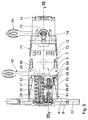
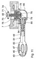
- Locking device 50 To the joint pivoting of the seat 10 and the backrest 15 in the synchro-mechanics against the force of the helical compression spring To be able to switch off 28 is one shown in FIGS. 6 to 8 Locking device 50 is provided.
- the locking device 50 includes a latch 51, which at the front seat support part 6 to a Swivel joint with pivot axis 52 is pivoted.
- the Pivot axis 52 substantially coincides with that of abutment 29 together.
- the bolt 51 At its free, remote from the pivot axis 52 end the bolt 51 has a horizontally arranged locking bolt 53, which is fixed to the bolt 51 and passes through it in such a way that it leads to both Sides over the bar 51 in the horizontal direction.
- Part of the locking device 50 is a cooperating with the latch 51 Counter body 54. This is on the front seat support part 6 to a Swivel joint with pivot axis 55 pivotally articulated.
- the Swivel axes 52, 55 are spaced apart and parallel.
- the counterbody 54 has two spaced apart, parallel, vertical and Plates 56 arranged perpendicular to the pivot axis 55. These have in rough approximation, a triangular shape, wherein the pivot axis 55 opposite side as a bar-peripheral portion 57 approximated is located on a circular arc section whose center through the Swivel axis 55 is formed.
- each substantially semi-circular latch receptacles 58 formed, wherein in each case two bolt receptacles in each one of the plates 56 in pairs with each other aligned.
- the width of the bolt receptacles 58 is complementary to Lock bolt 53 of the bolt 51 dimensioned such that the locking bolt 53rd engage substantially free of play in a pair of bolt receptacles 58 can.
- This engagement of the locking bolt 53 takes place in the bolt receptacles 58 such that in each case one of the two free ends of the locking bolt 53 in one of the two bolt receptacles 58 of the corresponding pair of Lock receptacles 58 engages.
- a pivot joint with pivot axis 59 is on the counter body 54 as Coupling element articulated a connecting member 60.
- the pivot axes 55 and 59 are spaced apart and parallel.
- about another Swivel joint with pivot axis 61 is the connecting member 60 at the first, short lever arm 33 of the rear seat support part 7 hinged.
- the Pivot axis 61 is in this case parallel to the pivot axes 8 and 59 and spaced apart from these.
- Fig. 7 shows the locking device 50 in a position in which the Lock bolt 53 in the side view of Figs. 7 and 8 furthest Left illustrated latch receptacle 58 is assigned. In this position is the rear seat support member 7 with the backrest support 14 in the furthest upright position.
- Fig. 8 shows the locking device 50 in a position in which the Latch bolt 53 of FIGS. 7 and 8 furthest to the right Latch receptacle 58 is assigned. In this position, the rear seat support part 7 with the backrest support 14 furthest back in a lying position inclined.
- the connecting member 60 therefore acts as mechanical translation member, which is the pivoting of the counter body 54 in relation to the pivoting of the rear seat support part. 7 translated.
- the locking device 50 is disabled, so that a synchronous relative movement between the seat support parts 6, 7 allows is. If the user overrides the synchronous mechanism, ie the seat support parts 6, 7 wants to lock against each other, he brings first by appropriate pressure on the backrest 15 and thus on the Backrest support 14 on the rear seat support part 7 latter in one desired relative position to the front seat support part 6. In connection the user actuates the operating handle 63 and moves the locking bolt 53 in the direction of the bolt peripheral portion 57 to.
- the connecting member 60 ensures by its translation function here, that despite the not too small Distance of the bolt receptacles 58 in the circumferential direction of the bolt peripheral portion 57 to each other a fine gradation of discrete relative positions the seat support parts 6, 7 is given.
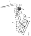
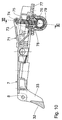
- Figs. 5 to 8 and Figs. 10 and 11 show details of the seat tilt adjusting device 13.
- the support axis 12 is for this purpose by a first lever arm 70 of a Ne Trentsverstellhebels 71, which is parallel to the pivot axis 8 Swivel axis 72 is pivotable.
- a second lever arm 73 is via a pivot joint with also to the pivot axis 8 parallel Swivel axis 74 a tilt adjustment screw 75 hinged. This is axial slidably and non-rotatably mounted.
- the tilt adjustment screw 75 engages in a tilt adjusting nut 76, which in a lower wall 77 of the rear Seat support part 7 rotatable, but in the direction of the tilt adjustment screw 75 is mounted immovably.
- the tilt adjusting nut 76 has a spur gear Cone section 78 on.
- the two cone sections 78, 79 thus form a straight bevel gear.
- a rotation axis 82 the set screw 75 and a rotation axis 83 of the tilt-actuated rotary handle 81 do not curse with each other, but intersect and enclose a right angle with each other.
- the end portion 80 is in a side wall 84 of a housing 85 which on the rear seat support part 7 is rotatable, but axially to the axis of rotation 83 of the tilt actuation rotary handle 81 immovably stored.
- the free end of the tilt actuation knob 81 is like that of the actuating rotary handle 42 configured as an oval handle 46, so refer to the relevant description of the actuating rotary handle 42 can be.
- a flexible Wave in particular a spring shaft.
- Such flexible waves for Power transmission are known.
- With such a flexible shaft can also a mechanical coupling of the rotational movements of the tilt actuation rotary handle 81 about the axis of rotation 83 on the one hand and the set screw 75 take place about the axis of rotation 82 on the other.
Landscapes
- Health & Medical Sciences (AREA)
- Dentistry (AREA)
- General Health & Medical Sciences (AREA)
- Chairs Characterized By Structure (AREA)
- Chairs For Special Purposes, Such As Reclining Chairs (AREA)
- Chair Legs, Seat Parts, And Backrests (AREA)
- Hydrogenated Pyridines (AREA)
- Pharmaceuticals Containing Other Organic And Inorganic Compounds (AREA)
- Plural Heterocyclic Compounds (AREA)
- Treatments For Attaching Organic Compounds To Fibrous Goods (AREA)
Priority Applications (1)
| Application Number | Priority Date | Filing Date | Title |
|---|---|---|---|
| PL04004811T PL1454568T3 (pl) | 2003-03-07 | 2004-03-02 | Krzesło, szczególnie krzesło biurowe |
Applications Claiming Priority (4)
| Application Number | Priority Date | Filing Date | Title |
|---|---|---|---|
| DE10309920A DE10309920A1 (de) | 2003-03-07 | 2003-03-07 | Stuhl, insbesondere Bürostuhl |
| DE10309921A DE10309921A1 (de) | 2003-03-07 | 2003-03-07 | Stuhl, insbesondere Bürostuhl |
| DE10309920 | 2003-03-07 | ||
| DE10309922A DE10309922A1 (de) | 2003-03-07 | 2003-03-07 | Stuhl, insbesondere Bürostuhl |
Publications (3)
| Publication Number | Publication Date |
|---|---|
| EP1454568A2 true EP1454568A2 (fr) | 2004-09-08 |
| EP1454568A3 EP1454568A3 (fr) | 2005-01-19 |
| EP1454568B1 EP1454568B1 (fr) | 2008-07-02 |
Family
ID=42315213
Family Applications (3)
| Application Number | Title | Priority Date | Filing Date |
|---|---|---|---|
| EP04004813A Expired - Lifetime EP1454569B1 (fr) | 2003-03-07 | 2004-03-02 | Chaise, en particulier chaise de bureau |
| EP04004812A Expired - Lifetime EP1454566B1 (fr) | 2003-03-07 | 2004-03-02 | Chaise, notamment chaise de bureau |
| EP04004811A Expired - Lifetime EP1454568B1 (fr) | 2003-03-07 | 2004-03-02 | Chaise, notamment chaise de bureau |
Family Applications Before (2)
| Application Number | Title | Priority Date | Filing Date |
|---|---|---|---|
| EP04004813A Expired - Lifetime EP1454569B1 (fr) | 2003-03-07 | 2004-03-02 | Chaise, en particulier chaise de bureau |
| EP04004812A Expired - Lifetime EP1454566B1 (fr) | 2003-03-07 | 2004-03-02 | Chaise, notamment chaise de bureau |
Country Status (9)
| Country | Link |
|---|---|
| US (3) | US20040212235A1 (fr) |
| EP (3) | EP1454569B1 (fr) |
| CN (3) | CN100486482C (fr) |
| AT (3) | ATE338492T1 (fr) |
| DE (6) | DE10309920A1 (fr) |
| DK (3) | DK1454569T3 (fr) |
| ES (3) | ES2309407T3 (fr) |
| PL (2) | PL1454566T3 (fr) |
| ZA (3) | ZA200401855B (fr) |
Families Citing this family (44)
| Publication number | Priority date | Publication date | Assignee | Title |
|---|---|---|---|---|
| NO317791B1 (no) * | 2002-01-04 | 2004-12-13 | Stokke As | Bevegelig ledd |
| ITVE20030014A1 (it) * | 2003-04-10 | 2004-10-11 | Imarc Spa | Dispositivo di regolazione del grado di precarica delle molle in meccanismi di sedie da ufficio. |
| US7500718B2 (en) * | 2004-05-14 | 2009-03-10 | Haworth, Inc. | Tilt tension mechanism for chair |
| US20060220431A1 (en) * | 2005-03-17 | 2006-10-05 | Kwa Ing C | Chair control device |
| US7261368B1 (en) * | 2006-02-27 | 2007-08-28 | Todd Clausnitzer | Ergonomic chair |
| CA2646948A1 (fr) * | 2006-03-24 | 2007-10-04 | Herman Miller Inc. | Meuble |
| WO2007124609A2 (fr) * | 2006-04-27 | 2007-11-08 | Vitra Patente Ag | Mecanisme pour une chaise |
| DE102006023982A1 (de) * | 2006-05-22 | 2007-12-06 | Wilkhahn Wilkening + Hahne Gmbh & Co. Kg | Stuhl |
| DE102006023981A1 (de) * | 2006-05-22 | 2007-12-06 | Wilkhahn Wilkening + Hahne Gmbh & Co. Kg | Stuhl |
| US20070290537A1 (en) * | 2006-06-13 | 2007-12-20 | Tung Yu Oa Co., Ltd. | Recliner |
| US7922630B1 (en) * | 2006-06-15 | 2011-04-12 | Roger Batca | Adjustable bicep curl support pads |
| DE102006049676B4 (de) * | 2006-10-18 | 2008-12-11 | Sedus Stoll Ag | Stuhl mit neigbarem Sitz |
| ATE451854T1 (de) * | 2007-01-22 | 2010-01-15 | Stoll Sedus Ag | Stuhl mit neigbarem sitz |
| CN102772053A (zh) | 2007-01-29 | 2012-11-14 | 赫尔曼米勒有限公司 | 座位结构及其使用方法 |
| ITMI20070718A1 (it) * | 2007-04-06 | 2008-10-07 | L & P Property Management Co | Dispositivo di regolazione per sedie regolabili e simili. |
| ITMI20070719A1 (it) * | 2007-04-06 | 2008-10-07 | L & P Property Management Co | Dispositivo di inclinazione per un sedile reclinabile. |
| US7467826B1 (en) * | 2007-08-14 | 2008-12-23 | Hurng Taih Plastic Master Batch Co., Ltd. | Resilience tilt-adjusted device of backrest |
| US8015981B2 (en) * | 2007-08-19 | 2011-09-13 | Anastasia Soare | Stencils and gauging device for aesthetically pleasing eyebrow shaping |
| EP2200479B1 (fr) * | 2007-09-20 | 2015-06-17 | Herman Miller, Inc. | Structure de support du corps |
| WO2009057168A1 (fr) * | 2007-10-30 | 2009-05-07 | Donati S.P.A. | Mécanisme de réglage de la précharge d'un ressort de rigidité pour sièges |
| US20110025111A1 (en) * | 2007-12-20 | 2011-02-03 | David Wornell | Seating systems incorporating self-inflating adjustable supports |
| US7530637B1 (en) * | 2008-03-18 | 2009-05-12 | Yao-Chuan Wu | Chair assembly |
| KR101564800B1 (ko) * | 2009-02-25 | 2015-10-30 | 도나티 에스.피.에이. | 의자의 등받이와 시트의 경사를 동조화하기 위한 장치 |
| ES2333768B1 (es) * | 2009-07-21 | 2010-10-13 | Actiu Berbegal Y Formas, S.A. | Silla de oficina. |
| KR101009490B1 (ko) * | 2010-04-28 | 2011-01-21 | 주식회사 토치 | 앉는 위치가 조절되는 좌판부의 이동구조를 갖는 의자 |
| US9962307B2 (en) | 2010-12-20 | 2018-05-08 | Restoration Robotics, Inc. | Adjustable hair transplantation chair |
| EP2725943B1 (fr) * | 2011-07-01 | 2017-08-23 | L&P Property Management Company | Mécanisme d'inclinaison pour un siège et siège |
| TW201311188A (zh) * | 2011-07-15 | 2013-03-16 | Itoki Corp | 搖椅及使用於其之彈簧單元 |
| DE202012002288U1 (de) * | 2012-03-08 | 2012-05-11 | Walter Knoll Ag & Co. Kg | Funktionsstuhl |
| CN102846067B (zh) * | 2012-09-18 | 2014-10-15 | 浙江永艺家具股份有限公司 | 一种转椅靠背锁定机构 |
| US11304528B2 (en) | 2012-09-20 | 2022-04-19 | Steelcase Inc. | Chair assembly with upholstery covering |
| USD697726S1 (en) | 2012-09-20 | 2014-01-21 | Steelcase Inc. | Chair |
| MX376921B (es) * | 2012-09-20 | 2025-03-07 | Steelcase Inc | Montaje de brazo de silla. |
| NO335007B1 (no) * | 2012-12-19 | 2014-08-25 | Scandinavian Business Seating AS | Anordning ved vippebeslag for stol |
| US8939509B2 (en) * | 2013-04-11 | 2015-01-27 | Hangzhou Zhongtai Industrial Group Co., Ltd. | Chair chassis |
| CN103330403B (zh) * | 2013-07-19 | 2016-02-10 | 湖州奥圣家具有限公司 | 一种转椅的调节装置 |
| CN103330404B (zh) * | 2013-07-19 | 2016-06-08 | 湖州奥圣家具有限公司 | 一种设有多功能调节装置的转椅 |
| CN105266431B (zh) * | 2014-06-02 | 2018-06-22 | 大河精工有限公司 | 椅子组件 |
| DE102016104638A1 (de) * | 2016-03-14 | 2017-09-14 | Burkhard Schmitz | Stuhl |
| CN106617848A (zh) * | 2016-11-08 | 2017-05-10 | 安吉恒林科技发展有限公司 | 椅子倾仰调节装置及带有该装置的椅子 |
| FI128663B (en) * | 2018-10-31 | 2020-09-30 | Easydoing Oy | Bridge support device for a saddle chair with split seat |
| US11246417B2 (en) * | 2019-08-07 | 2022-02-15 | Chen Raizman | Tilt-swivel mechanism chair |
| CN113729426B (zh) * | 2021-05-27 | 2025-11-28 | 广东联友办公家具有限公司 | 一种座椅底盘及座椅 |
| US12137817B2 (en) * | 2022-10-26 | 2024-11-12 | Comfordy Co., Ltd. | Interlocking mechanism for seat and back of chair |
Family Cites Families (34)
| Publication number | Priority date | Publication date | Assignee | Title |
|---|---|---|---|---|
| DE23360C (de) * | E. CALIX in Zürich, Schweiz | Mechanismus zum Verstellen von Stühlen und Tischen in vertikaler Richtung | ||
| US1730252A (en) * | 1927-04-25 | 1929-10-01 | Adjustable piajsto ok obgast bektch | |
| US2015138A (en) * | 1934-02-17 | 1935-09-24 | Benjamin H Drake | Chair |
| US2272980A (en) * | 1939-02-11 | 1942-02-10 | Mclellan | Chair construction |
| US2224543A (en) * | 1939-03-22 | 1940-12-10 | Frank B Harman | Swivel chair |
| DE1812282C3 (de) | 1968-12-03 | 1981-07-30 | Fritz Bauer + Söhne oHG, 8503 Altdorf | Hubvorrichtung zum stufenlosen Höhenverstellen von Tischplatten, Stuhlsitzen u.dgl. |
| DE3467498D1 (en) * | 1983-08-09 | 1987-12-23 | Pledge Office Chairs | Tilting mechanism for a chair |
| US4652050A (en) * | 1984-01-11 | 1987-03-24 | Herman Miller, Inc. | Chair tilt mechanism |
| DE8401000U1 (de) * | 1984-01-14 | 1984-04-05 | Mauser Waldeck AG, 3544 Waldeck | Drehsessel |
| CH668541A5 (de) * | 1986-01-07 | 1989-01-13 | Provenda Marketing Ag | Arbeitsstuhl, insbesondere zur verwendung als buerostuhl. |
| US4709963A (en) * | 1986-12-12 | 1987-12-01 | Milsco Manufacturing Company | Adjustable office chair |
| JPH0511791Y2 (fr) * | 1987-08-24 | 1993-03-24 | ||
| DE3741472A1 (de) * | 1987-12-08 | 1989-06-22 | Simon Desanta | Stuhl |
| US5106157A (en) * | 1989-03-01 | 1992-04-21 | Herman Miller, Inc. | Chair height and tilt adjustment mechanisms |
| ATE95680T1 (de) * | 1990-12-13 | 1993-10-15 | Stoll Kg Christof | Neigungsvorrichtung fuer ein sitzmoebel. |
| JPH0716457B2 (ja) * | 1991-06-26 | 1995-03-01 | 株式会社岡村製作所 | 椅子の背凭れの傾動緩衝装置 |
| IL103477A0 (en) * | 1992-10-20 | 1993-03-15 | Paltechnica Nitzanim | Office and like chairs |
| DE4324541A1 (de) * | 1993-07-22 | 1995-01-26 | Trendoffice Bueromoebel | Stuhl, insbesondere Bürostuhl |
| US5556163A (en) * | 1994-08-17 | 1996-09-17 | Eac Corporation | Automatically adjustable office and task chairs |
| DE4436145A1 (de) * | 1994-10-11 | 1996-04-18 | Kusch Co Sitzmoebel | Sitzmöbel |
| US5725276A (en) * | 1995-06-07 | 1998-03-10 | Ginat; Jonathan | Tilt back chair and control |
| US5765914A (en) * | 1995-06-07 | 1998-06-16 | Herman Miller, Inc. | Chair with a tilt control mechanism |
| DE59708116D1 (de) * | 1996-10-14 | 2002-10-10 | Vitra Patente Ag Muttenz | Stuhlmechanik |
| US5813726A (en) * | 1997-02-18 | 1998-09-29 | Hoover Universal, Inc. | Inertia locking device for a vehicle seat adjustment mechanism |
| TW414040U (en) * | 1997-09-10 | 2000-12-01 | Takano Co Ltd | Device for tilting, swaying and fastening |
| US6250715B1 (en) * | 1998-01-21 | 2001-06-26 | Herman Miller, Inc. | Chair |
| WO2000022959A1 (fr) * | 1998-10-20 | 2000-04-27 | Protoned B.V. | Systeme mecanique pour fauteuil |
| DE19922446B8 (de) * | 1999-05-07 | 2009-02-19 | Bock-1 Gmbh & Co. | Synchronmechanik für eine korrelierte Sitz-Rückenlehnen-Bewegung eines Bürostuhles |
| IT1308074B1 (it) * | 1999-06-04 | 2001-11-29 | Pro Cord Srl | Sedia con sedile e schienale oscillanti in modo sincronizzato |
| DE20004361U1 (de) * | 2000-03-10 | 2001-04-12 | FROLI Kunststoffwerk Heinrich Fromme oHG, 33758 Schloß Holte-Stukenbrock | Sitz für eine Stehhilfe oder für einen Büro- bzw. Werkstattstuhl |
| CA2310349A1 (fr) * | 2000-05-22 | 2001-11-22 | Todd D. Krupiczewicz | Fauteuil de bureau |
| US6607244B2 (en) * | 2001-04-02 | 2003-08-19 | Edward L. Stulik | Reclining chair |
| EP1228722B1 (fr) * | 2001-04-27 | 2002-08-14 | CO.FE.MO. S.p.A. | Dispositif d'appui élastique pour parties inclinables des chaises de bureau et analogues |
| US6585320B2 (en) * | 2001-06-15 | 2003-07-01 | Virco Mgmt. Corporation | Tilt control mechanism for a tilt back chair |
-
2003
- 2003-03-07 DE DE10309920A patent/DE10309920A1/de not_active Withdrawn
- 2003-03-07 DE DE10309922A patent/DE10309922A1/de not_active Withdrawn
- 2003-03-07 DE DE10309921A patent/DE10309921A1/de not_active Withdrawn
-
2004
- 2004-03-02 DE DE502004000132T patent/DE502004000132D1/de not_active Expired - Lifetime
- 2004-03-02 DK DK04004813T patent/DK1454569T3/da active
- 2004-03-02 DE DE502004001375T patent/DE502004001375D1/de not_active Expired - Fee Related
- 2004-03-02 ES ES04004811T patent/ES2309407T3/es not_active Expired - Lifetime
- 2004-03-02 DE DE502004007465T patent/DE502004007465D1/de not_active Expired - Lifetime
- 2004-03-02 EP EP04004813A patent/EP1454569B1/fr not_active Expired - Lifetime
- 2004-03-02 PL PL04004812T patent/PL1454566T3/pl unknown
- 2004-03-02 AT AT04004812T patent/ATE338492T1/de not_active IP Right Cessation
- 2004-03-02 DK DK04004811T patent/DK1454568T3/da active
- 2004-03-02 ES ES04004813T patent/ES2255691T3/es not_active Expired - Lifetime
- 2004-03-02 AT AT04004813T patent/ATE309721T1/de not_active IP Right Cessation
- 2004-03-02 EP EP04004812A patent/EP1454566B1/fr not_active Expired - Lifetime
- 2004-03-02 EP EP04004811A patent/EP1454568B1/fr not_active Expired - Lifetime
- 2004-03-02 PL PL04004811T patent/PL1454568T3/pl unknown
- 2004-03-02 AT AT04004811T patent/ATE399490T1/de not_active IP Right Cessation
- 2004-03-02 DK DK04004812T patent/DK1454566T3/da active
- 2004-03-02 ES ES04004812T patent/ES2273107T3/es not_active Expired - Lifetime
- 2004-03-05 CN CNB2004100079217A patent/CN100486482C/zh not_active Expired - Fee Related
- 2004-03-05 ZA ZA200401855A patent/ZA200401855B/xx unknown
- 2004-03-05 ZA ZA200401854A patent/ZA200401854B/xx unknown
- 2004-03-05 CN CNB2004100079221A patent/CN100486483C/zh not_active Expired - Fee Related
- 2004-03-05 ZA ZA200401853A patent/ZA200401853B/xx unknown
- 2004-03-05 US US10/792,771 patent/US20040212235A1/en not_active Abandoned
- 2004-03-05 CN CNA2004100079236A patent/CN1526347A/zh active Pending
- 2004-03-05 US US10/792,772 patent/US6945603B2/en not_active Expired - Fee Related
- 2004-03-08 US US10/793,770 patent/US7036882B2/en not_active Expired - Fee Related
Also Published As
Similar Documents
| Publication | Publication Date | Title |
|---|---|---|
| EP1454569B1 (fr) | Chaise, en particulier chaise de bureau | |
| DE69600110T2 (de) | Verbesserungen an Verstell- und Bedienungsvorrichtungen von bewegenden und verformbaren Teilen eines Bürostuhls | |
| EP3049040A1 (fr) | Siège | |
| WO2011141107A1 (fr) | Mécanisme de réglage d'une force de rappel agissant sur le dossier d'un siège et siège de bureau doté d'un mécanisme de ce type | |
| EP1138306B1 (fr) | Fauteuil de soins médicaux ou dentaires et repose tête pour un tel fauteuil | |
| DE102014226645A1 (de) | Verstellmechanik zur Einstellung einer auf eine Rückenlehne eines Stuhls einwirkenden Rückstellkraft und Bürostuhl mit einer solchen Verstellmechanik | |
| EP3120732A1 (fr) | Mecanisme de siege de bureau | |
| DE102016112119A1 (de) | Federungsvorrichtung | |
| EP3528664B1 (fr) | Dispositif de mécanisme synchrone et chaise en étant équipée | |
| EP1967095A2 (fr) | Chaise dotée d'un siège inclinable | |
| DE4400911A1 (de) | Drehgelenkbeschlag für einen Fahrzeugsitz mit einem oberen und einem unteren Beschlagteil und einem dazwischen angeordneten Taumelgetriebe | |
| EP0995371B1 (fr) | Chaise de bureau avec assise réglable en inclinaison | |
| DE10123231C2 (de) | Bürostuhl | |
| DE10147349A1 (de) | Medizinischer oder dentalmedizinischer Behandlungsstuhl | |
| WO2010028412A1 (fr) | Dispositif pour régler la résistance au pivotement d'un dossier | |
| DE2341790A1 (de) | Sitzmoebel. | |
| DE10124282C2 (de) | Sitzmöbel | |
| DE10123380C2 (de) | Sitzmöbel | |
| DE10330719B4 (de) | Verstellmechanismus für einen Bowdenzug | |
| DE19501664C2 (de) | Krafttrainingsgerät | |
| DE202020106493U1 (de) | Sitzmöbel oder Sitz- Liegemöbel | |
| EP1372562A2 (fr) | Fauteuil de traitement pour soins medicaux ou dentaires | |
| DE29903949U1 (de) | Stuhl mit verstellbarer Sitz- und Rückenlehnenneigung | |
| DE2004372C3 (de) | Sitzmöbel | |
| EP3865007A1 (fr) | Accoudoir, en particulier pour une chaise de bureau |
Legal Events
| Date | Code | Title | Description |
|---|---|---|---|
| PUAI | Public reference made under article 153(3) epc to a published international application that has entered the european phase |
Free format text: ORIGINAL CODE: 0009012 |
|
| AK | Designated contracting states |
Kind code of ref document: A2 Designated state(s): AT BE BG CH CY CZ DE DK EE ES FI FR GB GR HU IE IT LI LU MC NL PL PT RO SE SI SK TR |
|
| AX | Request for extension of the european patent |
Extension state: AL LT LV MK |
|
| PUAL | Search report despatched |
Free format text: ORIGINAL CODE: 0009013 |
|
| AK | Designated contracting states |
Kind code of ref document: A3 Designated state(s): AT BE BG CH CY CZ DE DK EE ES FI FR GB GR HU IE IT LI LU MC NL PL PT RO SE SI SK TR |
|
| AX | Request for extension of the european patent |
Extension state: AL LT LV MK |
|
| 17P | Request for examination filed |
Effective date: 20050609 |
|
| AKX | Designation fees paid |
Designated state(s): AT BE BG CH CY CZ DE DK EE ES FI FR GB GR HU IE IT LI LU MC NL PL PT RO SE SI SK TR |
|
| AXX | Extension fees paid |
Extension state: LT Payment date: 20050609 Extension state: AL Payment date: 20050609 Extension state: MK Payment date: 20050609 Extension state: LV Payment date: 20050609 |
|
| GRAP | Despatch of communication of intention to grant a patent |
Free format text: ORIGINAL CODE: EPIDOSNIGR1 |
|
| GRAS | Grant fee paid |
Free format text: ORIGINAL CODE: EPIDOSNIGR3 |
|
| GRAA | (expected) grant |
Free format text: ORIGINAL CODE: 0009210 |
|
| AK | Designated contracting states |
Kind code of ref document: B1 Designated state(s): AT BE BG CH CY CZ DE DK EE ES FI FR GB GR HU IE IT LI LU MC NL PL PT RO SE SI SK TR |
|
| AX | Request for extension of the european patent |
Extension state: AL LT LV MK |
|
| REG | Reference to a national code |
Ref country code: GB Ref legal event code: FG4D Free format text: NOT ENGLISH |
|
| REG | Reference to a national code |
Ref country code: CH Ref legal event code: EP |
|
| REF | Corresponds to: |
Ref document number: 502004007465 Country of ref document: DE Date of ref document: 20080814 Kind code of ref document: P |
|
| REG | Reference to a national code |
Ref country code: IE Ref legal event code: FG4D Free format text: LANGUAGE OF EP DOCUMENT: GERMAN |
|
| REG | Reference to a national code |
Ref country code: SE Ref legal event code: TRGR |
|
| PG25 | Lapsed in a contracting state [announced via postgrant information from national office to epo] |
Ref country code: SI Free format text: LAPSE BECAUSE OF FAILURE TO SUBMIT A TRANSLATION OF THE DESCRIPTION OR TO PAY THE FEE WITHIN THE PRESCRIBED TIME-LIMIT Effective date: 20080702 |
|
| REG | Reference to a national code |
Ref country code: ES Ref legal event code: FG2A Ref document number: 2309407 Country of ref document: ES Kind code of ref document: T3 |
|
| REG | Reference to a national code |
Ref country code: PL Ref legal event code: T3 |
|
| PG25 | Lapsed in a contracting state [announced via postgrant information from national office to epo] |
Ref country code: PT Free format text: LAPSE BECAUSE OF FAILURE TO SUBMIT A TRANSLATION OF THE DESCRIPTION OR TO PAY THE FEE WITHIN THE PRESCRIBED TIME-LIMIT Effective date: 20081202 |
|
| REG | Reference to a national code |
Ref country code: IE Ref legal event code: FD4D |
|
| PG25 | Lapsed in a contracting state [announced via postgrant information from national office to epo] |
Ref country code: BG Free format text: LAPSE BECAUSE OF FAILURE TO SUBMIT A TRANSLATION OF THE DESCRIPTION OR TO PAY THE FEE WITHIN THE PRESCRIBED TIME-LIMIT Effective date: 20081002 Ref country code: FI Free format text: LAPSE BECAUSE OF FAILURE TO SUBMIT A TRANSLATION OF THE DESCRIPTION OR TO PAY THE FEE WITHIN THE PRESCRIBED TIME-LIMIT Effective date: 20080702 |
|
| PG25 | Lapsed in a contracting state [announced via postgrant information from national office to epo] |
Ref country code: EE Free format text: LAPSE BECAUSE OF FAILURE TO SUBMIT A TRANSLATION OF THE DESCRIPTION OR TO PAY THE FEE WITHIN THE PRESCRIBED TIME-LIMIT Effective date: 20080702 Ref country code: IE Free format text: LAPSE BECAUSE OF FAILURE TO SUBMIT A TRANSLATION OF THE DESCRIPTION OR TO PAY THE FEE WITHIN THE PRESCRIBED TIME-LIMIT Effective date: 20080702 |
|
| PLBE | No opposition filed within time limit |
Free format text: ORIGINAL CODE: 0009261 |
|
| STAA | Information on the status of an ep patent application or granted ep patent |
Free format text: STATUS: NO OPPOSITION FILED WITHIN TIME LIMIT |
|
| PG25 | Lapsed in a contracting state [announced via postgrant information from national office to epo] |
Ref country code: RO Free format text: LAPSE BECAUSE OF FAILURE TO SUBMIT A TRANSLATION OF THE DESCRIPTION OR TO PAY THE FEE WITHIN THE PRESCRIBED TIME-LIMIT Effective date: 20080702 Ref country code: SK Free format text: LAPSE BECAUSE OF FAILURE TO SUBMIT A TRANSLATION OF THE DESCRIPTION OR TO PAY THE FEE WITHIN THE PRESCRIBED TIME-LIMIT Effective date: 20080702 |
|
| 26N | No opposition filed |
Effective date: 20090403 |
|
| PG25 | Lapsed in a contracting state [announced via postgrant information from national office to epo] |
Ref country code: MC Free format text: LAPSE BECAUSE OF NON-PAYMENT OF DUE FEES Effective date: 20090331 |
|
| PGFP | Annual fee paid to national office [announced via postgrant information from national office to epo] |
Ref country code: CZ Payment date: 20100223 Year of fee payment: 7 Ref country code: DK Payment date: 20100325 Year of fee payment: 7 Ref country code: LU Payment date: 20100324 Year of fee payment: 7 |
|
| PGFP | Annual fee paid to national office [announced via postgrant information from national office to epo] |
Ref country code: PL Payment date: 20100223 Year of fee payment: 7 |
|
| PGFP | Annual fee paid to national office [announced via postgrant information from national office to epo] |
Ref country code: AT Payment date: 20100322 Year of fee payment: 7 |
|
| PGFP | Annual fee paid to national office [announced via postgrant information from national office to epo] |
Ref country code: BE Payment date: 20100323 Year of fee payment: 7 |
|
| PG25 | Lapsed in a contracting state [announced via postgrant information from national office to epo] |
Ref country code: GR Free format text: LAPSE BECAUSE OF FAILURE TO SUBMIT A TRANSLATION OF THE DESCRIPTION OR TO PAY THE FEE WITHIN THE PRESCRIBED TIME-LIMIT Effective date: 20081003 |
|
| PGFP | Annual fee paid to national office [announced via postgrant information from national office to epo] |
Ref country code: SE Payment date: 20100324 Year of fee payment: 7 |
|
| PGFP | Annual fee paid to national office [announced via postgrant information from national office to epo] |
Ref country code: NL Payment date: 20110328 Year of fee payment: 8 Ref country code: FR Payment date: 20110401 Year of fee payment: 8 Ref country code: CH Payment date: 20110328 Year of fee payment: 8 |
|
| PG25 | Lapsed in a contracting state [announced via postgrant information from national office to epo] |
Ref country code: HU Free format text: LAPSE BECAUSE OF FAILURE TO SUBMIT A TRANSLATION OF THE DESCRIPTION OR TO PAY THE FEE WITHIN THE PRESCRIBED TIME-LIMIT Effective date: 20090103 |
|
| PGFP | Annual fee paid to national office [announced via postgrant information from national office to epo] |
Ref country code: ES Payment date: 20110324 Year of fee payment: 8 Ref country code: GB Payment date: 20110324 Year of fee payment: 8 |
|
| PG25 | Lapsed in a contracting state [announced via postgrant information from national office to epo] |
Ref country code: TR Free format text: LAPSE BECAUSE OF FAILURE TO SUBMIT A TRANSLATION OF THE DESCRIPTION OR TO PAY THE FEE WITHIN THE PRESCRIBED TIME-LIMIT Effective date: 20080702 |
|
| BERE | Be: lapsed |
Owner name: DAUPHIN ENTWICKLUNGS- U. BETEILIGUNGS G.M.B.H. Effective date: 20110331 |
|
| PG25 | Lapsed in a contracting state [announced via postgrant information from national office to epo] |
Ref country code: CY Free format text: LAPSE BECAUSE OF FAILURE TO SUBMIT A TRANSLATION OF THE DESCRIPTION OR TO PAY THE FEE WITHIN THE PRESCRIBED TIME-LIMIT Effective date: 20080702 |
|
| PGFP | Annual fee paid to national office [announced via postgrant information from national office to epo] |
Ref country code: IT Payment date: 20110331 Year of fee payment: 8 |
|
| REG | Reference to a national code |
Ref country code: DK Ref legal event code: EBP |
|
| REG | Reference to a national code |
Ref country code: SE Ref legal event code: EUG |
|
| PG25 | Lapsed in a contracting state [announced via postgrant information from national office to epo] |
Ref country code: CZ Free format text: LAPSE BECAUSE OF NON-PAYMENT OF DUE FEES Effective date: 20110302 Ref country code: AT Free format text: LAPSE BECAUSE OF NON-PAYMENT OF DUE FEES Effective date: 20110302 |
|
| PG25 | Lapsed in a contracting state [announced via postgrant information from national office to epo] |
Ref country code: BE Free format text: LAPSE BECAUSE OF NON-PAYMENT OF DUE FEES Effective date: 20110331 |
|
| PG25 | Lapsed in a contracting state [announced via postgrant information from national office to epo] |
Ref country code: DK Free format text: LAPSE BECAUSE OF NON-PAYMENT OF DUE FEES Effective date: 20110331 |
|
| PGFP | Annual fee paid to national office [announced via postgrant information from national office to epo] |
Ref country code: DE Payment date: 20120522 Year of fee payment: 9 |
|
| REG | Reference to a national code |
Ref country code: PL Ref legal event code: LAPE |
|
| PG25 | Lapsed in a contracting state [announced via postgrant information from national office to epo] |
Ref country code: PL Free format text: LAPSE BECAUSE OF NON-PAYMENT OF DUE FEES Effective date: 20110302 |
|
| REG | Reference to a national code |
Ref country code: NL Ref legal event code: V1 Effective date: 20121001 |
|
| REG | Reference to a national code |
Ref country code: CH Ref legal event code: PL |
|
| GBPC | Gb: european patent ceased through non-payment of renewal fee |
Effective date: 20120302 |
|
| REG | Reference to a national code |
Ref country code: FR Ref legal event code: ST Effective date: 20121130 |
|
| PG25 | Lapsed in a contracting state [announced via postgrant information from national office to epo] |
Ref country code: FR Free format text: LAPSE BECAUSE OF NON-PAYMENT OF DUE FEES Effective date: 20120402 Ref country code: GB Free format text: LAPSE BECAUSE OF NON-PAYMENT OF DUE FEES Effective date: 20120302 Ref country code: CH Free format text: LAPSE BECAUSE OF NON-PAYMENT OF DUE FEES Effective date: 20120331 Ref country code: LI Free format text: LAPSE BECAUSE OF NON-PAYMENT OF DUE FEES Effective date: 20120331 |
|
| PG25 | Lapsed in a contracting state [announced via postgrant information from national office to epo] |
Ref country code: IT Free format text: LAPSE BECAUSE OF NON-PAYMENT OF DUE FEES Effective date: 20120302 |
|
| PG25 | Lapsed in a contracting state [announced via postgrant information from national office to epo] |
Ref country code: NL Free format text: LAPSE BECAUSE OF NON-PAYMENT OF DUE FEES Effective date: 20121001 |
|
| PG25 | Lapsed in a contracting state [announced via postgrant information from national office to epo] |
Ref country code: SE Free format text: LAPSE BECAUSE OF NON-PAYMENT OF DUE FEES Effective date: 20110303 |
|
| PG25 | Lapsed in a contracting state [announced via postgrant information from national office to epo] |
Ref country code: LU Free format text: LAPSE BECAUSE OF NON-PAYMENT OF DUE FEES Effective date: 20110302 |
|
| REG | Reference to a national code |
Ref country code: ES Ref legal event code: FD2A Effective date: 20130710 |
|
| PG25 | Lapsed in a contracting state [announced via postgrant information from national office to epo] |
Ref country code: ES Free format text: LAPSE BECAUSE OF NON-PAYMENT OF DUE FEES Effective date: 20120303 |
|
| REG | Reference to a national code |
Ref country code: DE Ref legal event code: R119 Ref document number: 502004007465 Country of ref document: DE Effective date: 20131001 |
|
| PG25 | Lapsed in a contracting state [announced via postgrant information from national office to epo] |
Ref country code: DE Free format text: LAPSE BECAUSE OF NON-PAYMENT OF DUE FEES Effective date: 20131001 |