EP1454708B1 - Vorrichtung zur Herstellung von Bedieneinheiten für Türen oder Fenster - Google Patents
Vorrichtung zur Herstellung von Bedieneinheiten für Türen oder Fenster Download PDFInfo
- Publication number
- EP1454708B1 EP1454708B1 EP04425121A EP04425121A EP1454708B1 EP 1454708 B1 EP1454708 B1 EP 1454708B1 EP 04425121 A EP04425121 A EP 04425121A EP 04425121 A EP04425121 A EP 04425121A EP 1454708 B1 EP1454708 B1 EP 1454708B1
- Authority
- EP
- European Patent Office
- Prior art keywords
- station
- profile
- bit
- pin
- working
- Prior art date
- Legal status (The legal status is an assumption and is not a legal conclusion. Google has not performed a legal analysis and makes no representation as to the accuracy of the status listed.)
- Expired - Lifetime
Links
- 239000011159 matrix material Substances 0.000 claims description 21
- 238000003780 insertion Methods 0.000 claims description 17
- 230000037431 insertion Effects 0.000 claims description 17
- 238000005520 cutting process Methods 0.000 claims description 11
- 238000004080 punching Methods 0.000 claims description 9
- 238000000605 extraction Methods 0.000 claims description 6
- 238000007373 indentation Methods 0.000 claims description 6
- 230000005484 gravity Effects 0.000 claims description 2
- 238000011144 upstream manufacturing Methods 0.000 claims description 2
- 239000002184 metal Substances 0.000 description 5
- 238000004519 manufacturing process Methods 0.000 description 3
- 238000003754 machining Methods 0.000 description 2
- 230000003213 activating effect Effects 0.000 description 1
- 230000004913 activation Effects 0.000 description 1
- 239000007795 chemical reaction product Substances 0.000 description 1
- 230000001419 dependent effect Effects 0.000 description 1
- 238000000034 method Methods 0.000 description 1
- 229920002994 synthetic fiber Polymers 0.000 description 1
Images




Classifications
-
- E—FIXED CONSTRUCTIONS
- E05—LOCKS; KEYS; WINDOW OR DOOR FITTINGS; SAFES
- E05B—LOCKS; ACCESSORIES THEREFOR; HANDCUFFS
- E05B17/00—Accessories in connection with locks
- E05B17/0004—Lock assembling or manufacturing
-
- B—PERFORMING OPERATIONS; TRANSPORTING
- B23—MACHINE TOOLS; METAL-WORKING NOT OTHERWISE PROVIDED FOR
- B23P—METAL-WORKING NOT OTHERWISE PROVIDED FOR; COMBINED OPERATIONS; UNIVERSAL MACHINE TOOLS
- B23P15/00—Making specific metal objects by operations not covered by a single other subclass or a group in this subclass
-
- B—PERFORMING OPERATIONS; TRANSPORTING
- B23—MACHINE TOOLS; METAL-WORKING NOT OTHERWISE PROVIDED FOR
- B23P—METAL-WORKING NOT OTHERWISE PROVIDED FOR; COMBINED OPERATIONS; UNIVERSAL MACHINE TOOLS
- B23P2700/00—Indexing scheme relating to the articles being treated, e.g. manufactured, repaired, assembled, connected or other operations covered in the subgroups
- B23P2700/08—Fittings for doors and windows of buildings
Definitions
- the present invention relates to an apparatus for making accessory elements for door or window frames according to the preamble of claim 1.
- Such an apparatus is known from EP-A-1232830 .
- One of the main accessories is the operating unit which enables the mobile frame of the door or window to be positioned in its different configurations (namely, turn opened, tilt opened or closed) upon actuation of a handle located on the outside surface of the mobile frame itself.
- the operating unit usually consists of a pair of rod segments (each, in practice, being a length of flat metal profile) joined to each other by a connecting element, or "drive rod", as it is called in the jargon of the trade, positioned between the two segments and attached to them using pins which are normally present on the drive rod and which may be inserted in the holes in the corresponding ends of the segments.
- the two metal segments also have other seats or holes, made close to the ends opposite those attached to the drive, for their connection, during frame assembly, to the moving parts which open and close the mobile frame (push bolts or lock terminals) and to drive elements (such as corner drives) for tilt opening of the mobile frame.
- the operating unit structured in this way is obtained using a method according to which the rod segments are made by a special cutting machine from a metal profile, with a suitably shaped cross-section, which can be attached with a matching fit in a channel present on the frame profile.
- the length of the segments depends on the dimensions (height) of the mobile frame in which they will be inserted. Once cut, the segments are further machined to create the seats and/or holes mentioned, which are needed in order to connect them to the drive rod and to the opening/closing and drive elements.
- the segments are assembled in succession, each being attached to the operating elements until assembly on the frame profile is complete.
- the operating unit is made from a single rod of the same height as the door or window frame to which it has to be fitted and the accessories may be assembled directly on the rod before the latter is inserted into the sliding channel of the mobile frame (see Italian patent applications BO2000A000117 and BO2001A000080 by the same Applicant as the present).
- the operating unit is made using an apparatus that comprises at least the following:
- the second station for working the continuous profile portion comprises means for working the profile so as to at least form and/or attach drive means and locking and/or operating means.
- the present invention therefore has for an aim to provide an apparatus for making operating units for doors or window frames, especially metal frames, that is extremely fast, economical as a whole, and applies a limited number of elements to the rod, while at the same time maintaining the quality of the end product at a high level.
- the apparatus according to the invention is used for making accessory elements for door or window frames (not illustrated since they are well within the knowledge of those familiar with the trade) comprising a profile constituting a channel in which there slides and/or there is coupled at least one operating rod 1 for a handle assembly which acts in conjunction with drive means 2 to make the operating rod 1 slide in both directions along the channel.
- the operating rod is also equipped with locking and/or operating elements 3 actuated by the handle assembly. The elements 3 are described in further detail below.
- the apparatus 100 essentially comprises:
- the apparatus 100 may comprise:
- the apparatus 100 may comprise the aforementioned stations one after the other in the working direction A, according to the following configuration (purely by way of example): the feed station 4; the punching station 11; the perforating station 6; the separating or cutting station 12; the fixing station 10; and the station 7 for inserting the pins 8.
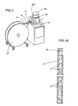
- the feed station 4, punching station 11, perforating station 6, separating station 12, fixing station 10 and insertion station 7 each consist of a lower unit 15 for positioning and moving the profile 5 and the pins 8 and a corresponding plurality of working means 16 located above a surface on which the profile 5 is fed in the direction A and opposite the lower unit 15.
- the magazine 13 may consist of a self-contained cylindrical cartridge 13c containing a plurality of pins 8 placed one after the other.
- the cartridge 13c can be inserted quickly and easily into a cylindrical fitting 39 made close to the insertion station 7 and designed to position one pin 8 at a time in a zone for extracting the pins 8, which are gravity fed (as described in more detail below).
- the cartridge 13c consists of a self-contained transparent cylinder with a predetermined number of pins 8 inside it and replaceable by another similar cartridge 13c when the pins 8 in the first cartridge 13c are finished.
- the aforementioned lower unit 15 comprises a base plate 32, a base cradle 17 housing an intermediate matrix 18, and an upper element 19 for closing and guiding the aforementioned working means 16.
- the matrix 18 has a central channel 20 through which the profile 5 to be machined passes in the working direction A, forming the feed surface.
- the feed station 4 may comprise a guide 21 for the passage of the profile 5 fed in by a cartridge 22, and a pair of power-driven opposing rollers 23 located upstream of the guide 21 in the working direction A and between which the profile 5 to be fed to the other stations 11, 6, 12, 10, 7 is interposed.
- the profile 5 is of the continuous type, made of a synthetic material, and is rolled up on the cartridge 22 outside the apparatus 100.
- the aforementioned punching station 11 comprises a first vertical bit 16a associated with drive means 24 and mobile (see arrows F16a) towards and away from the matrix 18 which, at the working area of the first bit 16a, has an opening 25 on the central channel 20, this opening being shaped to match the shape of the cutting edge of the first bit 16a so that the latter, when activated, forms a tapered feature 26 on the profile 5 constituting a stop and operating element on the rod 1.
- the perforating station 6 comprises a second vertical bit 16b, with circular cross section, associated with drive means 24 and mobile (see arrow F16b) towards and away from the matrix 18 which, at the working area of the second bit 16b, has a circular opening 27, which, when the second bit 16b is activated, makes a circular hole 9 through the profile 5.
- the hole 9 may be used as a seat for a pin 8 or it may be left free and used later for fitting the operating elements when the rod 1 is mounted on the frame.
- the insertion station 7, located downstream of the matrix 18 in the working direction A, comprises:
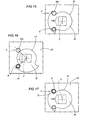
- the extraction and feed means 14 comprise a circular plate or feeder plate 30 located under the matrix 18 and presenting, on a part of its circumference, an indentation 31 for intercepting a single pin 8 when the plate 30 rotates (see arrows F30) about its vertical axis Z between:
- the next pin 8 waiting to be fed from the magazine 13 to the open seat 28 is positioned over the plate 30 (see Figures 3 , 6 and 15 ) and is held in this position both by the cylindrical fitting 39 and by the thickness of the plate 30, thanks also to a movement of the latter.
- the pin 8 moves down further thanks not only to the indentation 31 in the plate 30 but also to the presence of a guide channel 32c made in the base plate 32 and a related guide channel 17c made in the cradle 17 (see Figure 19 ). This downward movement enables the pin 8 to come free of the cylindrical fitting 39 and to be fed to the open seat 28.
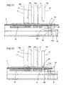
- the vertical drive means 29 comprise a pushing cylinder 29c located under the base plate 32 and mobile between a retracted idle position where the cylinder 29c is under the base plate 32, and a raised working position with the pin 8 on it in such manner as to insert the pin 8 into a hole 9 in the profile 5 (see Figure 11 and arrow F29).
- the insertion station 7 may be equipped with sensors 38 for detecting the pins 8 at the magazine 13 and at the open seat 28 in the matrix 18 (see Figure 6 ).
- the next station namely the fixing station 10 comprises a third vertical bit 16c associated with drive means 24 and mobile (see arrows F16a) towards and away from the matrix 18 which, at the working area of the third bit 16c, has an open slot-like seat 33 forming a passage that supports the pin 8 in a respective hole 9 in the profile 5 downstream of the fixing station 10 in the working direction A.
- the third bit 16c has a wedge-shaped working edge enabling the pin 8 to be fixed in place by deforming a part 8a of it that protrudes upwards from the profile 5 when the latter is withdrawn (see arrow F10) from the insertion station 7 to the fixing station 10.
- the cutting station 12 located between the perforating station 6 and the fixing station 10, comprises a fourth vertical cutting bit 16d associated with drive means 24 and mobile (see arrows F16d) towards and away from the matrix 18 which, at the working area of the fourth bit 16d, has a slot-like seat 34 extending transversally to the working direction A and designed to separate the part of the profile 5 forming a finished rod 1 from the remaining portion of the continuous profile 5.
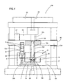
- the means 24 for driving the aforementioned bits 16a, 16b, 16c, 16d comprise a single actuating element 35 which moves the bits 16a, 16b, 16c, 16d up and down.
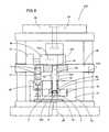
- each of the bits 16a, 16b, 16c, 16d and the actuator 35 there are interposed blocks 36 for selectively moving the bits 16a, 16b, 16c, 16d individually through a drive control unit 37 between a selected working position in which the block 36 pushes the respective bit 16a, 16b, 16c, 16d (see Figure 5 ) so that the bit 16a, 16b, 16c, 16d performs a working movement towards the profile 5, and a selected idle position in which the block 36 positions at the respective bit 16a, 16b, 16c, 16d a matching seat 37s through which the bit 16a, 16b, 16c, 16d can slide freely (see arrows F37 and Figure 4 ).
- the control unit 37 for driving the selection blocks 36, the motor for driving the two rollers 23 that feed the profile 5, the actuator 35 and the cylinder 29c are controlled by a central microprocessor unit 41 (illustrated as a block Figure 2 ) which enables machining to be carried out according to predetermined sequences depending on data entered by the operator, such as, for example, the total length of the rod 1, the height of the door or window frame to which the rod is to be applied, the type of locking and operating elements, and so on.
- the movements of the control unit 37, of the actuator 35 and of the cylinder 29c are accomplished by electropneumatic devices.
- An apparatus made as described above works in the following manner, starting from an initial configuration such as that illustrated in Figure 3 and after the operator has entered the required data in the central microprocessor unit 41.
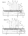
- the two rollers 23 feed the profile 5 until the end of it is positioned at the punching station 11 where the first bit 16a is activated and moves down to make a tapered feature 26 defining a locking and operating element (see Figures 6 and 7 ).
- the profile 5 is fed in the working direction A until a predetermined part of it is positioned at the perforating station 6 where the second bit 16b is activated and makes a hole 9 in it (see Figure 8 ).
- the cylinder 29c is now activated and lifts the pin 8 to partly insert it into the hole 9 (see Figure 11 ).
- the rollers 23 withdraw the profile 5 to the point at the end of the open seat 28 in the matrix 18 where the third bit 16c is activated to deform a part of the pin 8 in such a way as to fix the pin 8 in the profile 5(see Figure 13 ).
- the end of the rod 1 is positioned at the separating station 12 where the fourth bit 16d cuts the worked rod 1 from the remainder of the profile 5 (see Figure 14 ).
- An apparatus made as described above achieves the aforementioned aims thanks to its extremely compact structure, the use of only one accessory element to be applied, namely the pins, and its extremely fast working speed.
Landscapes
- Engineering & Computer Science (AREA)
- Manufacturing & Machinery (AREA)
- Mechanical Engineering (AREA)
- Automatic Assembly (AREA)
- Selective Calling Equipment (AREA)
- Control By Computers (AREA)
- Power-Operated Mechanisms For Wings (AREA)
- User Interface Of Digital Computer (AREA)
- Wing Frames And Configurations (AREA)
- Press Drives And Press Lines (AREA)
Claims (18)
- Vorrichtung zur Herstellung von Zubehörelementen für Tür- oder Fensterrahmen, die ein Profil beinhalten, das einen Kanal für das Gleiten und/oder Einkuppeln zumindest einer Betätigungsstange (1) für eine Griffgruppe bildet, die derart mit Getriebemitteln (2) zusammenwirkt, dass sie das Gleiten der Betätigungsstange (1) in beiden Richtungen entlang des Kanals bewirkt; wobei die Betätigungsstange (1) auch mit Verriegelungs- und/oder Bedienelementen (3) ausgestattet ist, die durch die Griffgruppe betätigt werden; wobei die Vorrichtung Folgendes beinhaltet:- eine Station (4) für das Zuführen eines Profils (5) in einer Arbeitsrichtung (A), das einen Querschnitt aufweist, der sich genau dem Gleitkanal anpasst;- eine Station (6) zum Perforieren des Profils (5), um mehrere Löcher im Profil (5) anzufertigen;wobei die Vorrichtung dadurch gekennzeichnet ist, dass sie ferner Folgendes beinhaltet:- eine Station (7) zum Einsetzen mehrerer Zapfen (8) in entsprechende Löcher (9), die von der Perforierstation (6) im Profil (5) angefertigt wurden;- eine Station (10) zum Fixieren jedes Zapfens (8) im entsprechenden Loch (9), um ein Getriebeelement (2) oder ein Verriegelungs- und/oder Bedienelement (3) zu bilden;- ein Magazin (13) für die Zapfen (8) nahe der Einsetzstation (7), das mit Mitteln (14) ausgestattet ist, um die Zapfen (8) einzeln zu entnehmen und der Einsetzstation (7) zuzuführen;- wobei die Zuführstation (4), die Perforierstation (6), die Fixierstation (10) und die Einsetzstation (7) bestehen aus: einer unteren Einheit (15) zur Positionierung und Bewegung des Profils (5) und der Zapfen (8) sowie aus mehreren entsprechenden Bearbeitungsmitteln (16), die oberhalb einer Fläche, auf der das Profil (5) in Richtung (A) zugeführt wird, und gegenüber der unteren Einheit (15) angeordnet sind;- wobei die untere Einheit (15) beinhaltet: eine Grundplatte (32), einen Grundschlitten (17) zur Aufnahme einer zwischenliegenden Matrix (18), und ein oberes Element (19) zum Schließen und Führen der Bearbeitungsmittel (16);- wobei die Entnahme- und Zuführmittel (14) eine kreisförmige Platte (30) aufweisen, die unter der Matrix (18) angeordnet ist und an einem Teil ihres Umfangs eine Vertiefung (31) aufweist, die dazu dient, einen einzelnen Zapfen (8) abzufangen, wenn sich die Platte (30) um ihre vertikale Achse (Z) zwischen einer Entnahmestellung dreht, in der sich die Vertiefung (31) beim Magazin (13) befindet, um den Zapfen (8) abzufangen und zu positionieren, und einer Arbeitsstellung, an der die kreisförmige Platte (30) um einen Winkel (α) gedreht wurde, um den Zapfen (8) zu einer offenen Aufnahme (28) zu bewegen.
- Vorrichtung nach Anspruch 1, dadurch gekennzeichnet, dass sie ferner eine Station (11) zum Stanzen des Profils (5) beinhaltet, um Bearbeitungen an dem Profil (5) auszuführen, die zumindest einen Teil der Verriegelungs- und/oder Bedienelemente (3) bilden.
- Vorrichtung nach Anspruch 1, dadurch gekennzeichnet, dass sie ferner eine Station (12) zum Trennen oder Zuschneiden des Profils (5) auf eine vorbestimmte Länge beinhaltet, um die Betätigungsstange (1) zu bilden.
- Vorrichtung nach den Ansprüchen 1 bis 3, dadurch gekennzeichnet, dass die Vorrichtung (100) nacheinander in Arbeitsrichtung (A) Folgendes beinhaltet: die Zuführstation (4); die Stanzstation (11); die Perforierstation (6); die Trenn- oder Schneidstation (12); die Fixierstation (10); und die Station (7) zum Einsetzen der Zapfen (8).
- Vorrichtung nach den Ansprüchen 1 bis 3, dadurch gekennzeichnet, dass die Stanzstation (11) und die Trennstation (12) ebenfalls bestehen aus: einer unteren Einheit (15) zur Positionierung und Bewegung des Profils (5) und der Zapfen (8) sowie aus mehreren entsprechenden Bearbeitungsmitteln (16), die oberhalb einer Fläche, auf der das Profil (5) in Richtung (A) zugeführt wird, und gegenüber der unteren Einheit (15) angeordnet sind.
- Vorrichtung nach Anspruch 5, dadurch gekennzeichnet, dass die Zuführstation (4) eine Führung (21) für den Durchgang des von einer Ladeeinrichtung (22) zugeführten Profils (5) und ein Paar einander gegenüberliegender kraftbetriebener Rollen (23) beinhaltet, die in Arbeitsrichtung (A) betrachtet stromaufwärts vor der Führung (21) angeordnet sind und zwischen denen das Profil (5) eingelegt ist, um den anderen Stationen (11, 6, 12, 10, 7) zugeführt zu werden.
- Vorrichtung nach Anspruch 6, dadurch gekennzeichnet, dass das Profil (5) endloser Art ist und auf der Ladeeinrichtung (22) außerhalb der Vorrichtung (100) aufgerollt ist.
- Vorrichtung nach Anspruch 5, dadurch gekennzeichnet, dass die Stanzstation (11) ein erstes vertikales Stanzwerkzeug (16a) beinhaltet, das mit Antriebseinrichtungen (24) verbunden ist und zu der Matrix (18) hin und von dieser weg bewegt werden kann, welche in dem Arbeitsbereich des ersten Stanzwerkzeuges (16a) eine Öffnung (25) auf dem mittleren Kanal (20) aufweist, wobei diese Öffnung so geformt ist, dass sie der Form der Schneidkante des ersten Stanzwerkzeuges (16a) entspricht, so dass das letztgenannte bei seiner Aktivierung eine konisch zulaufende Bearbeitung (26) auf dem Profil (5) ausformt, die ein Anschlag- und Bedienelement auf der Stange (1) bildet.
- Vorrichtung nach Anspruch 5, dadurch gekennzeichnet, dass die Perforierstation (6) ein zweites vertikales Stanzwerkzeug (16b) mit kreisförmigem Querschnitt beinhaltet, das mit Antriebseinrichtungen (24) verbunden ist und zu der Matrix (18) hin und von dieser weg bewegt werden kann, welche in dem Arbeitsbereich des zweiten Stanzwerkzeuges (16b) eine kreisförmige Öffnung (27) aufweist, welche bei Aktivierung des zweiten Stanzwerkzeuges (16b) ein kreisförmiges Loch (9) durch das Profil (5) anfertigt.
- Vorrichtung nach Anspruch 5, dadurch gekennzeichnet, dass die Einsetzstation (7) Folgendes beihaltet:- Antriebseinrichtungen (29) zum vertikalen Bewegen des Zapfens (8) von einer unteren Arbeitsstellung in eine angehobene Stellung, in der der Zapfen (8) in en Loch (9) eingesetzt wird, das im Profil (5) angefertigt und über dem Zapfen (8) angeordnet ist.
- Vorrichtung nach Anspruch 10, dadurch gekennzeichnet, dass die vertikalen Antriebseinrichtungen (29) einen Schubzylinder (29c) beinhalten, der unter einer Grundplatte (32) der Vorrichtung (100) angeordnet ist und beweglich ist zwischen einer zurückgezogenen Ruhestellung, in der sich der Zylinder (29c) unterhalb der Grundplatte (32) befindet, und einer angehobenen Arbeitsstellung, wobei der Zapfen (8) so darauf angeordnet ist, dass der Zapfen (8) in ein Loch (9) in dem Profil (5) eingeführt wird.
- Vorrichtung nach Anspruch 5, dadurch gekennzeichnet, dass die Fixierstation (10) ein drittes vertikales Stanzwerkzeug (16c) beinhaltet, das mit Antriebseinrichtungen (24) verbunden ist und zu der Matrix (18) hin und von dieser weg bewegt werden kann, welche in dem Arbeitsbereich des dritten Stanzwerkzeuges (16c) eine offene langlochförmige Aufnahme (33) aufweist, die einen Durchgang zum Halten des Zapfens (8) bildet, der in einem entsprechenden Loch (9) in dem Profil (5) und in Arbeitsrichtung (A) betrachtet stromabwärts nach der Fixierstation (10) angeordnet ist; wobei das dritte Stanzwerkzeug (16c) eine keilförmige Arbeitskante aufweist, die das Fixieren des Zapfens (8) in seiner Stellung durch Verformen eines Teils (8a) des Zapfens beim Zurückziehen des Profils (5) von der Einsetzstation (7) zu der Fixierstation (10) ermögücht.
- Vorrichtung nach Anspruch 10, dadurch gekennzeichnet, dass die offene langlochförmige Aufnahme (28) in der Matrix (18) eine Hinterschneidung (28s) aufweist, die in der Kante der Aufnahme (28) ausgefertigt ist und als Auflage für die Unterseite des Zapfens (8) während des Zurückziehens von der Einsetzstation (7) zu der Fixierstation (10) dient.
- Vorrichtung nach Anspruch 5, dadurch gekennzeichnet, dass die Schneidstation (12), die zwischen der Perforierstation (6) und der Fixierstation (10) angeordnet ist, eine viertes vertikales Stanzwerkzeug (16d) zum Schneiden beinhaltet, das mit Antriebseinrichtungen (24) verbunden ist und zu der Matrix (18) hin und von dieser weg bewegt werden kann, welche in dem Arbeitsbereich des vierten Stanzwerkzeuges (16d) eine langlochförmige Aufnahme (34) aufweist, die sich quer zur Arbeitsrichtung (A) erstreckt und dazu dient, den Teil des Profils (5), der eine fertiggestellte Stange (1) bildet, von dem restlichen Teil des endlosen Profils (5) abzutrennen.
- Vorrichtung nach Anspruch 5, dadurch gekennzeichnet, dass die Einrichtungen (16) zur Bearbeitung des endlosen Profils (5) mehrere Werkzeuge (16a, 16b, 16c, 16d) beinhalten, die von Einrichtungen (24) angetrieben werden, die ein einziges Betätigungselement (35) beinhalten, welches die Werkzeuge (16a, 16b, 16c, 16d) auf- und abwärts bewegt;
wobei zwischen jedem der Stanzwerkzeuge (16a, 16b, 16c, 16d) und dem Betätigungselement (35) Blöcke (36) angeordnet sind, die dazu dienen, die Stanzwerkzeuge (16a, 16b, 16c, 16d) selektiv und einzeln über eine Antriebssteuereinheit (37) zu bewegen und zwar zwischen einer vorbestimmten Arbeitsstellung, in der der Block (36) derart gegen das entsprechende Stanzwerkzeug (16a, 16b, 16c, 16d) drückt, dass das Stanzwerkzeug (16a, 16b, 16c, 16d) eine Arbeitsbewegung zu dem Profil (5) hin ausführt, und einer vorbestimmten Ruhestellung, in der der Block (36) an dem entsprechenden Stanzwerkzeug (16a, 16b, 16c, 16d) eine passende Aufnahme (37s) positioniert, durch die das Stanzwerkzeug (16a, 16b, 16c, 16d) frei hindurchgleiten kann. - Vorrichtung nach Anspruch 10, dadurch gekennzeichnet, dass die Einsetzstation (7) mit Sensoreinrichtungen (38) zur Erfassung der Zapfen (8) an dem Magazin (13) und an der offenen Aufnahme (28) in der Matrix (18) ausgestattet ist.
- Vorrichtung nach Anspruch 1, dadurch gekennzeichnet, dass das Magazin (13) aus einer eigenständigen zylindrischen Ladeeinrichtung (13c) besteht, die mehrere hintereinander angeordnete Zapfen (8) enthält, wobei der Zylinder (13c) in ein zylindrisches Anschlussteil (39) eingeführt werden kann, das in der Nähe der Einsetzstation (7) ausgefertigt ist und dazu dient, jeweils einen Zapfen (8) in einem Bereich für die Entnahme der durch Schwerkraftwirkung zugeführten Zapfen (8) anzuordnen.
- Vorrichtung nach Anspruch 17, dadurch gekennzeichnet, dass die Ladeeinrichtung (13c) aus einem eigenständigen transparenten Zylinder besteht, der eine vorbestimmte Anzahl von Zapfen (8) enthält und durch eine andere, ähnliche Ladeeinrichtung (13c) ersetzt werden kann, wenn die Zapfen (8) in der ersten Ladeeinrichtung (13c) aufgebraucht sind.
Applications Claiming Priority (2)
| Application Number | Priority Date | Filing Date | Title |
|---|---|---|---|
| IT000119A ITBO20030119A1 (it) | 2003-03-05 | 2003-03-05 | Apparecchiatura per la realizzazione di gruppi di manovra per infissi |
| ITBO20030119 | 2003-03-05 |
Publications (3)
| Publication Number | Publication Date |
|---|---|
| EP1454708A2 EP1454708A2 (de) | 2004-09-08 |
| EP1454708A3 EP1454708A3 (de) | 2006-04-19 |
| EP1454708B1 true EP1454708B1 (de) | 2009-01-21 |
Family
ID=32800658
Family Applications (1)
| Application Number | Title | Priority Date | Filing Date |
|---|---|---|---|
| EP04425121A Expired - Lifetime EP1454708B1 (de) | 2003-03-05 | 2004-02-26 | Vorrichtung zur Herstellung von Bedieneinheiten für Türen oder Fenster |
Country Status (5)
| Country | Link |
|---|---|
| EP (1) | EP1454708B1 (de) |
| AT (1) | ATE421405T1 (de) |
| DE (1) | DE602004019157D1 (de) |
| ES (1) | ES2321512T3 (de) |
| IT (1) | ITBO20030119A1 (de) |
Families Citing this family (6)
| Publication number | Priority date | Publication date | Assignee | Title |
|---|---|---|---|---|
| ITBO20060893A1 (it) * | 2006-12-28 | 2008-06-29 | Gsg Int Spa | Linea di realizzazione di accessori di manovra per telai di infissi. |
| IT1393807B1 (it) | 2008-10-30 | 2012-05-11 | Gsg Int Spa | Dispositivo di chiusura per infissi. |
| ITBO20090101A1 (it) * | 2009-02-23 | 2010-08-24 | Procoel Srl | Sistema per avanzamento di inserti o chiodi, in plastica o metallo, uno per volta |
| KR101406462B1 (ko) * | 2012-05-15 | 2014-06-13 | (주)엘지하우시스 | 슬라이딩 창호용 크리센트 자동 조립장치 |
| KR101402364B1 (ko) * | 2012-05-29 | 2014-06-11 | (주)엘지하우시스 | 크리센트 브라켓 자동 조립장치 |
| CN108057792B (zh) * | 2017-12-31 | 2024-04-23 | 苏州通锦精密工业股份有限公司 | 铝型材框架生产线的装配角码装置 |
Family Cites Families (11)
| Publication number | Priority date | Publication date | Assignee | Title |
|---|---|---|---|---|
| DE3316358C2 (de) * | 1983-05-05 | 1987-04-02 | IMA - Klessmann GmbH & Co KG, 4830 Gütersloh | Vorrichtung zum Einpressen von Möbel-Montageteilen |
| US4694974A (en) * | 1985-06-14 | 1987-09-22 | Michael Heck | Escapement apparatus for an automatic screw feeding machine |
| FR2612107B1 (fr) * | 1987-03-12 | 1993-09-03 | Ferco Int Usine Ferrures | Dispositif d'assemblage des differentes pieces d'un element de ferrure |
| FR2620758B1 (fr) * | 1987-09-21 | 1989-12-01 | Ferco Int Usine Ferrures | Machine d'assemblage des differentes pieces d'un element de ferrure |
| FR2664932A1 (fr) * | 1990-07-20 | 1992-01-24 | Bezault Sa | Dispositif de verrouillage a la fermeture des chassis de fenetre a tringle et a cremone. |
| FR2676948B1 (fr) * | 1991-06-03 | 1993-08-13 | Ferco Int Usine Ferrures | Machine de pose de ferrures sur des profiles, notamment de pose de gaches sur des profiles destines, apres assemblage ulterieur, a constituer des dormants de porte ou fenetre. |
| DE19906758A1 (de) * | 1998-02-20 | 1999-10-14 | Lemuth Gmbh | Fenster- und Türflügelbeschlag und Verfahren zu dessen Herstellung |
| DE19909400A1 (de) * | 1999-03-04 | 2000-09-07 | Siegenia Frank Kg | Fenster oder Tür, Beschlag für ein Fenster oder eine Tür, sowie Verfahren zur Herstellung eines Fenster oder einer Tür |
| ITBO20000117A1 (it) * | 2000-03-07 | 2001-09-07 | Giesse Spa | Gruppo di manovra per infissi , metodo per la realizzazione del gruppo di manovra e macchina attuante tale metodo . |
| DE20015094U1 (de) * | 2000-09-01 | 2000-12-21 | Kanehl, Wolfgang, 41812 Erkelenz | Vorrichtung zum lagegerichteten Vereinzeln von Kopfstiften |
| ITBO20010080A1 (it) * | 2001-02-14 | 2002-08-14 | Gsg Int Spa | Metodo di realizzazione di elementi accessori per infissi ed apparecchiature attuante tale metodo |
-
2003
- 2003-03-05 IT IT000119A patent/ITBO20030119A1/it unknown
-
2004
- 2004-02-26 DE DE602004019157T patent/DE602004019157D1/de not_active Expired - Lifetime
- 2004-02-26 EP EP04425121A patent/EP1454708B1/de not_active Expired - Lifetime
- 2004-02-26 ES ES04425121T patent/ES2321512T3/es not_active Expired - Lifetime
- 2004-02-26 AT AT04425121T patent/ATE421405T1/de not_active IP Right Cessation
Also Published As
| Publication number | Publication date |
|---|---|
| EP1454708A2 (de) | 2004-09-08 |
| ES2321512T3 (es) | 2009-06-08 |
| DE602004019157D1 (de) | 2009-03-12 |
| ATE421405T1 (de) | 2009-02-15 |
| ITBO20030119A1 (it) | 2004-09-06 |
| EP1454708A3 (de) | 2006-04-19 |
Similar Documents
| Publication | Publication Date | Title |
|---|---|---|
| CA2243369C (en) | Dual mini-blind cutter | |
| US6079306A (en) | Cutting-off machine for a venetian blind | |
| US6178857B1 (en) | Method of end trimming of blinds | |
| US6196099B1 (en) | End trimming apparatus for blinds | |
| US6758120B2 (en) | Blind cut down apparatus | |
| AU709969B2 (en) | End trimming apparatus for venetian blinds | |
| US7681480B2 (en) | Blind and shade cutting center for cutting two different window covering products | |
| CA2381138A1 (en) | Cutting apparatus and method for venetian blinds | |
| EP1078143B1 (de) | Vorrichtung für die herstellung von lamellen | |
| EP1454708A2 (de) | Verfahren zur Herstellung von Bedieneinheiten für Türen oder Fenster | |
| US7059230B2 (en) | Adjustable blind cutting device | |
| CA2724730C (en) | Automatically configurable blind cutting center | |
| KR102386442B1 (ko) | Pvc 창호용 자동 절단 장치 | |
| CN120244579B (zh) | 一种电梯导轨组件自动切割设备 | |
| EP1132169B1 (de) | Steuereinheit für Fensterrahmen, Verfahren zu seiner Herstellung und Maschine zum Durchführen des Verfahrens | |
| EP1232830B2 (de) | Gerät zur Herstellung von Treibstangen von Griffeinheiten für Fensterrahmen | |
| US6021701A (en) | System for cutting and finishing muntins | |
| WO2005005085A1 (en) | Modular blind cutting center | |
| EP1637300B1 (de) | Halte- und Zuführeinrichtung für Korkplatten | |
| GB2279896A (en) | Tooling apparatus | |
| EP0344890A1 (de) | Strangpressvorrichtung mit rotierender Walze | |
| CN113560693A (zh) | 一种板材仿形机 | |
| CN115351200B (zh) | 带自动定长的送筋切断设备 | |
| JP2001018109A (ja) | 台形状ワークのプレス切断装置 | |
| JPH0631496B2 (ja) | ブラインドのスラツト切断装置 |
Legal Events
| Date | Code | Title | Description |
|---|---|---|---|
| PUAI | Public reference made under article 153(3) epc to a published international application that has entered the european phase |
Free format text: ORIGINAL CODE: 0009012 |
|
| AK | Designated contracting states |
Kind code of ref document: A2 Designated state(s): AT BE BG CH CY CZ DE DK EE ES FI FR GB GR HU IE IT LI LU MC NL PT RO SE SI SK TR |
|
| AX | Request for extension of the european patent |
Extension state: AL HR LT LV MK |
|
| PUAL | Search report despatched |
Free format text: ORIGINAL CODE: 0009013 |
|
| AK | Designated contracting states |
Kind code of ref document: A3 Designated state(s): AT BE BG CH CY CZ DE DK EE ES FI FR GB GR HU IE IT LI LU MC NL PT RO SE SI SK TR |
|
| AX | Request for extension of the european patent |
Extension state: AL LT LV MK |
|
| 17P | Request for examination filed |
Effective date: 20060502 |
|
| AKX | Designation fees paid |
Designated state(s): AT BE BG CH CY CZ DE DK EE ES FI FR GB GR HU IE IT LI LU MC NL PT RO SE SI SK TR |
|
| 17Q | First examination report despatched |
Effective date: 20080312 |
|
| GRAP | Despatch of communication of intention to grant a patent |
Free format text: ORIGINAL CODE: EPIDOSNIGR1 |
|
| GRAS | Grant fee paid |
Free format text: ORIGINAL CODE: EPIDOSNIGR3 |
|
| GRAA | (expected) grant |
Free format text: ORIGINAL CODE: 0009210 |
|
| AK | Designated contracting states |
Kind code of ref document: B1 Designated state(s): AT BE BG CH CY CZ DE DK EE ES FI FR GB GR HU IE IT LI LU MC NL PT RO SE SI SK TR |
|
| REG | Reference to a national code |
Ref country code: GB Ref legal event code: FG4D |
|
| REG | Reference to a national code |
Ref country code: CH Ref legal event code: EP |
|
| REG | Reference to a national code |
Ref country code: IE Ref legal event code: FG4D |
|
| REF | Corresponds to: |
Ref document number: 602004019157 Country of ref document: DE Date of ref document: 20090312 Kind code of ref document: P |
|
| REG | Reference to a national code |
Ref country code: GR Ref legal event code: EP Ref document number: 20090401049 Country of ref document: GR |
|
| PG25 | Lapsed in a contracting state [announced via postgrant information from national office to epo] |
Ref country code: NL Free format text: LAPSE BECAUSE OF FAILURE TO SUBMIT A TRANSLATION OF THE DESCRIPTION OR TO PAY THE FEE WITHIN THE PRESCRIBED TIME-LIMIT Effective date: 20090121 |
|
| REG | Reference to a national code |
Ref country code: ES Ref legal event code: FG2A Ref document number: 2321512 Country of ref document: ES Kind code of ref document: T3 |
|
| NLV1 | Nl: lapsed or annulled due to failure to fulfill the requirements of art. 29p and 29m of the patents act | ||
| PG25 | Lapsed in a contracting state [announced via postgrant information from national office to epo] |
Ref country code: SI Free format text: LAPSE BECAUSE OF FAILURE TO SUBMIT A TRANSLATION OF THE DESCRIPTION OR TO PAY THE FEE WITHIN THE PRESCRIBED TIME-LIMIT Effective date: 20090121 Ref country code: FI Free format text: LAPSE BECAUSE OF FAILURE TO SUBMIT A TRANSLATION OF THE DESCRIPTION OR TO PAY THE FEE WITHIN THE PRESCRIBED TIME-LIMIT Effective date: 20090121 |
|
| PG25 | Lapsed in a contracting state [announced via postgrant information from national office to epo] |
Ref country code: SE Free format text: LAPSE BECAUSE OF FAILURE TO SUBMIT A TRANSLATION OF THE DESCRIPTION OR TO PAY THE FEE WITHIN THE PRESCRIBED TIME-LIMIT Effective date: 20090421 Ref country code: AT Free format text: LAPSE BECAUSE OF FAILURE TO SUBMIT A TRANSLATION OF THE DESCRIPTION OR TO PAY THE FEE WITHIN THE PRESCRIBED TIME-LIMIT Effective date: 20090121 Ref country code: PT Free format text: LAPSE BECAUSE OF FAILURE TO SUBMIT A TRANSLATION OF THE DESCRIPTION OR TO PAY THE FEE WITHIN THE PRESCRIBED TIME-LIMIT Effective date: 20090622 |
|
| PG25 | Lapsed in a contracting state [announced via postgrant information from national office to epo] |
Ref country code: BE Free format text: LAPSE BECAUSE OF FAILURE TO SUBMIT A TRANSLATION OF THE DESCRIPTION OR TO PAY THE FEE WITHIN THE PRESCRIBED TIME-LIMIT Effective date: 20090121 Ref country code: MC Free format text: LAPSE BECAUSE OF NON-PAYMENT OF DUE FEES Effective date: 20090228 |
|
| REG | Reference to a national code |
Ref country code: CH Ref legal event code: PL |
|
| PG25 | Lapsed in a contracting state [announced via postgrant information from national office to epo] |
Ref country code: DK Free format text: LAPSE BECAUSE OF FAILURE TO SUBMIT A TRANSLATION OF THE DESCRIPTION OR TO PAY THE FEE WITHIN THE PRESCRIBED TIME-LIMIT Effective date: 20090121 Ref country code: EE Free format text: LAPSE BECAUSE OF FAILURE TO SUBMIT A TRANSLATION OF THE DESCRIPTION OR TO PAY THE FEE WITHIN THE PRESCRIBED TIME-LIMIT Effective date: 20090121 Ref country code: LI Free format text: LAPSE BECAUSE OF NON-PAYMENT OF DUE FEES Effective date: 20090228 Ref country code: CZ Free format text: LAPSE BECAUSE OF FAILURE TO SUBMIT A TRANSLATION OF THE DESCRIPTION OR TO PAY THE FEE WITHIN THE PRESCRIBED TIME-LIMIT Effective date: 20090121 Ref country code: CH Free format text: LAPSE BECAUSE OF NON-PAYMENT OF DUE FEES Effective date: 20090228 |
|
| PLBE | No opposition filed within time limit |
Free format text: ORIGINAL CODE: 0009261 |
|
| STAA | Information on the status of an ep patent application or granted ep patent |
Free format text: STATUS: NO OPPOSITION FILED WITHIN TIME LIMIT |
|
| PG25 | Lapsed in a contracting state [announced via postgrant information from national office to epo] |
Ref country code: RO Free format text: LAPSE BECAUSE OF FAILURE TO SUBMIT A TRANSLATION OF THE DESCRIPTION OR TO PAY THE FEE WITHIN THE PRESCRIBED TIME-LIMIT Effective date: 20090121 Ref country code: SK Free format text: LAPSE BECAUSE OF FAILURE TO SUBMIT A TRANSLATION OF THE DESCRIPTION OR TO PAY THE FEE WITHIN THE PRESCRIBED TIME-LIMIT Effective date: 20090121 |
|
| GBPC | Gb: european patent ceased through non-payment of renewal fee |
Effective date: 20090421 |
|
| 26N | No opposition filed |
Effective date: 20091022 |
|
| PG25 | Lapsed in a contracting state [announced via postgrant information from national office to epo] |
Ref country code: BG Free format text: LAPSE BECAUSE OF FAILURE TO SUBMIT A TRANSLATION OF THE DESCRIPTION OR TO PAY THE FEE WITHIN THE PRESCRIBED TIME-LIMIT Effective date: 20090421 Ref country code: IE Free format text: LAPSE BECAUSE OF NON-PAYMENT OF DUE FEES Effective date: 20090226 |
|
| PG25 | Lapsed in a contracting state [announced via postgrant information from national office to epo] |
Ref country code: GB Free format text: LAPSE BECAUSE OF NON-PAYMENT OF DUE FEES Effective date: 20090421 |
|
| PG25 | Lapsed in a contracting state [announced via postgrant information from national office to epo] |
Ref country code: LU Free format text: LAPSE BECAUSE OF NON-PAYMENT OF DUE FEES Effective date: 20090226 |
|
| PG25 | Lapsed in a contracting state [announced via postgrant information from national office to epo] |
Ref country code: HU Free format text: LAPSE BECAUSE OF FAILURE TO SUBMIT A TRANSLATION OF THE DESCRIPTION OR TO PAY THE FEE WITHIN THE PRESCRIBED TIME-LIMIT Effective date: 20090722 |
|
| PG25 | Lapsed in a contracting state [announced via postgrant information from national office to epo] |
Ref country code: TR Free format text: LAPSE BECAUSE OF FAILURE TO SUBMIT A TRANSLATION OF THE DESCRIPTION OR TO PAY THE FEE WITHIN THE PRESCRIBED TIME-LIMIT Effective date: 20090121 |
|
| PG25 | Lapsed in a contracting state [announced via postgrant information from national office to epo] |
Ref country code: CY Free format text: LAPSE BECAUSE OF FAILURE TO SUBMIT A TRANSLATION OF THE DESCRIPTION OR TO PAY THE FEE WITHIN THE PRESCRIBED TIME-LIMIT Effective date: 20090121 |
|
| PGFP | Annual fee paid to national office [announced via postgrant information from national office to epo] |
Ref country code: GR Payment date: 20140225 Year of fee payment: 11 |
|
| REG | Reference to a national code |
Ref country code: GR Ref legal event code: ML Ref document number: 20090401049 Country of ref document: GR Effective date: 20150902 |
|
| PG25 | Lapsed in a contracting state [announced via postgrant information from national office to epo] |
Ref country code: GR Free format text: LAPSE BECAUSE OF NON-PAYMENT OF DUE FEES Effective date: 20150902 |
|
| REG | Reference to a national code |
Ref country code: FR Ref legal event code: PLFP Year of fee payment: 13 |
|
| PGFP | Annual fee paid to national office [announced via postgrant information from national office to epo] |
Ref country code: IT Payment date: 20160224 Year of fee payment: 13 Ref country code: ES Payment date: 20160321 Year of fee payment: 13 |
|
| PGFP | Annual fee paid to national office [announced via postgrant information from national office to epo] |
Ref country code: FR Payment date: 20160229 Year of fee payment: 13 |
|
| PGFP | Annual fee paid to national office [announced via postgrant information from national office to epo] |
Ref country code: DE Payment date: 20160502 Year of fee payment: 13 |
|
| REG | Reference to a national code |
Ref country code: DE Ref legal event code: R119 Ref document number: 602004019157 Country of ref document: DE |
|
| REG | Reference to a national code |
Ref country code: FR Ref legal event code: ST Effective date: 20171031 |
|
| PG25 | Lapsed in a contracting state [announced via postgrant information from national office to epo] |
Ref country code: DE Free format text: LAPSE BECAUSE OF NON-PAYMENT OF DUE FEES Effective date: 20170901 Ref country code: FR Free format text: LAPSE BECAUSE OF NON-PAYMENT OF DUE FEES Effective date: 20170228 |
|
| PG25 | Lapsed in a contracting state [announced via postgrant information from national office to epo] |
Ref country code: IT Free format text: LAPSE BECAUSE OF NON-PAYMENT OF DUE FEES Effective date: 20170226 |
|
| REG | Reference to a national code |
Ref country code: ES Ref legal event code: FD2A Effective date: 20180703 |
|
| PG25 | Lapsed in a contracting state [announced via postgrant information from national office to epo] |
Ref country code: ES Free format text: LAPSE BECAUSE OF NON-PAYMENT OF DUE FEES Effective date: 20170227 |