EP1454731A1 - Procédé pour produire une poignée de porte pour véhicules - Google Patents
Procédé pour produire une poignée de porte pour véhicules Download PDFInfo
- Publication number
- EP1454731A1 EP1454731A1 EP04005101A EP04005101A EP1454731A1 EP 1454731 A1 EP1454731 A1 EP 1454731A1 EP 04005101 A EP04005101 A EP 04005101A EP 04005101 A EP04005101 A EP 04005101A EP 1454731 A1 EP1454731 A1 EP 1454731A1
- Authority
- EP
- European Patent Office
- Prior art keywords
- tube
- slide
- pipe
- handle
- injection mold
- Prior art date
- Legal status (The legal status is an assumption and is not a legal conclusion. Google has not performed a legal analysis and makes no representation as to the accuracy of the status listed.)
- Granted
Links
- 238000004519 manufacturing process Methods 0.000 title claims abstract description 13
- 238000002347 injection Methods 0.000 claims abstract description 19
- 239000007924 injection Substances 0.000 claims abstract description 19
- 238000000034 method Methods 0.000 claims description 34
- 230000008878 coupling Effects 0.000 claims description 22
- 238000010168 coupling process Methods 0.000 claims description 22
- 238000005859 coupling reaction Methods 0.000 claims description 22
- 230000013011 mating Effects 0.000 claims description 14
- 239000000463 material Substances 0.000 claims description 10
- 238000005266 casting Methods 0.000 claims description 7
- 238000003466 welding Methods 0.000 claims description 7
- 238000003780 insertion Methods 0.000 claims description 6
- 230000037431 insertion Effects 0.000 claims description 6
- 238000000465 moulding Methods 0.000 claims description 6
- 150000001875 compounds Chemical class 0.000 claims description 5
- 238000001746 injection moulding Methods 0.000 claims description 4
- 238000010438 heat treatment Methods 0.000 claims description 2
- 239000012778 molding material Substances 0.000 abstract 1
- MPDDTAJMJCESGV-CTUHWIOQSA-M (3r,5r)-7-[2-(4-fluorophenyl)-5-[methyl-[(1r)-1-phenylethyl]carbamoyl]-4-propan-2-ylpyrazol-3-yl]-3,5-dihydroxyheptanoate Chemical compound C1([C@@H](C)N(C)C(=O)C2=NN(C(CC[C@@H](O)C[C@@H](O)CC([O-])=O)=C2C(C)C)C=2C=CC(F)=CC=2)=CC=CC=C1 MPDDTAJMJCESGV-CTUHWIOQSA-M 0.000 description 2
- 230000003993 interaction Effects 0.000 description 2
- 239000004033 plastic Substances 0.000 description 2
- 240000005561 Musa balbisiana Species 0.000 description 1
- 235000018290 Musa x paradisiaca Nutrition 0.000 description 1
- 230000000295 complement effect Effects 0.000 description 1
- 238000001816 cooling Methods 0.000 description 1
- 230000000694 effects Effects 0.000 description 1
- 239000000945 filler Substances 0.000 description 1
- 239000003292 glue Substances 0.000 description 1
- 239000011796 hollow space material Substances 0.000 description 1
- 238000007373 indentation Methods 0.000 description 1
- 230000002093 peripheral effect Effects 0.000 description 1
- 230000005855 radiation Effects 0.000 description 1
- 238000005507 spraying Methods 0.000 description 1
- 238000003860 storage Methods 0.000 description 1
- 229920001169 thermoplastic Polymers 0.000 description 1
- 239000004416 thermosoftening plastic Substances 0.000 description 1
Images





Classifications
-
- E—FIXED CONSTRUCTIONS
- E05—LOCKS; KEYS; WINDOW OR DOOR FITTINGS; SAFES
- E05B—LOCKS; ACCESSORIES THEREFOR; HANDCUFFS
- E05B85/00—Details of vehicle locks not provided for in groups E05B77/00 - E05B83/00
- E05B85/10—Handles
- E05B85/14—Handles pivoted about an axis parallel to the wing
- E05B85/16—Handles pivoted about an axis parallel to the wing a longitudinal grip part being pivoted at one end about an axis perpendicular to the longitudinal axis of the grip part
-
- B—PERFORMING OPERATIONS; TRANSPORTING
- B29—WORKING OF PLASTICS; WORKING OF SUBSTANCES IN A PLASTIC STATE IN GENERAL
- B29C—SHAPING OR JOINING OF PLASTICS; SHAPING OF MATERIAL IN A PLASTIC STATE, NOT OTHERWISE PROVIDED FOR; AFTER-TREATMENT OF THE SHAPED PRODUCTS, e.g. REPAIRING
- B29C45/00—Injection moulding, i.e. forcing the required volume of moulding material through a nozzle into a closed mould; Apparatus therefor
- B29C45/17—Component parts, details or accessories; Auxiliary operations
- B29C45/26—Moulds
- B29C45/261—Moulds having tubular mould cavities
- B29C45/2614—Moulds having tubular mould cavities for manufacturing bent tubular articles using an undercut forming mould core
-
- E—FIXED CONSTRUCTIONS
- E05—LOCKS; KEYS; WINDOW OR DOOR FITTINGS; SAFES
- E05B—LOCKS; ACCESSORIES THEREFOR; HANDCUFFS
- E05B81/00—Power-actuated vehicle locks
- E05B81/54—Electrical circuits
- E05B81/64—Monitoring or sensing, e.g. by using switches or sensors
- E05B81/76—Detection of handle operation; Detection of a user approaching a handle; Electrical switching actions performed by door handles
-
- B—PERFORMING OPERATIONS; TRANSPORTING
- B29—WORKING OF PLASTICS; WORKING OF SUBSTANCES IN A PLASTIC STATE IN GENERAL
- B29L—INDEXING SCHEME ASSOCIATED WITH SUBCLASS B29C, RELATING TO PARTICULAR ARTICLES
- B29L2031/00—Other particular articles
- B29L2031/30—Vehicles, e.g. ships or aircraft, or body parts thereof
- B29L2031/3005—Body finishings
- B29L2031/3029—Handgrips
-
- B—PERFORMING OPERATIONS; TRANSPORTING
- B29—WORKING OF PLASTICS; WORKING OF SUBSTANCES IN A PLASTIC STATE IN GENERAL
- B29L—INDEXING SCHEME ASSOCIATED WITH SUBCLASS B29C, RELATING TO PARTICULAR ARTICLES
- B29L2031/00—Other particular articles
- B29L2031/46—Knobs or handles, push-buttons, grips
- B29L2031/463—Grips, handles
-
- E—FIXED CONSTRUCTIONS
- E05—LOCKS; KEYS; WINDOW OR DOOR FITTINGS; SAFES
- E05B—LOCKS; ACCESSORIES THEREFOR; HANDCUFFS
- E05B17/00—Accessories in connection with locks
- E05B17/0004—Lock assembling or manufacturing
-
- E—FIXED CONSTRUCTIONS
- E05—LOCKS; KEYS; WINDOW OR DOOR FITTINGS; SAFES
- E05B—LOCKS; ACCESSORIES THEREFOR; HANDCUFFS
- E05B81/00—Power-actuated vehicle locks
- E05B81/54—Electrical circuits
- E05B81/64—Monitoring or sensing, e.g. by using switches or sensors
- E05B81/76—Detection of handle operation; Detection of a user approaching a handle; Electrical switching actions performed by door handles
- E05B81/78—Detection of handle operation; Detection of a user approaching a handle; Electrical switching actions performed by door handles as part of a hands-free locking or unlocking operation
Definitions
- a hollow space is closed at both ends in the handle shaft generated.
- the handle shaft can be constructed in several layers, for which a so-called Two-plastic spraying process is used.
- the cavity interior of the Grip shafts are inaccessible and cannot be used to hold one Control electronics can be used.
- the one mentioned in the preamble of claim 1 is cheaper Process that as a handle shaft a continuous tube with a tube entrance is generated at one end of the handle and a tube outlet at the other end of the handle.
- the Pipe wall in the handle end area a lateral opening, in which later a button is installed.
- the button is via an electrical connection cable connected to control electronics, which go through the pipe entrance Tube is inserted.
- the control electronics protrudes the connected cable out of the pipe outlet.
- the opposite Actuator attachment is integrated in a cover, which after inserting the Control electronics to close the pipe entrance.
- Door handle mainly has the disadvantage that the tube is non-uniform Has tube wall thickness. Thinner pipe wall areas lead to so-called "sink marks" on the handle shaft, which the good appearance of the finished door handle significantly affect. With the known method high quality door handles could not be manufactured.
- the invention has for its object a reliable method for Manufacture of a door handle of the type mentioned in the preamble of claim 1 develop which is the inexpensive manufacture of high quality handles allows. This is through the measures specified in claim 1 achieved, which have the following special meaning.
- a main slide moves into the to produce the tubular cavity Injection mold, which corresponds to the course of the handle shaft is curved. It has a banana shape. The retracted borders Main slide with its foot piece a branch room in the Injection mold, which has the negative profile of the actuator approach. With the head of the main slide acts in a special, even closer descriptive way together an auxiliary slide, which in turn transversely to The main slide moves into the injection mold and its flank moves towards the Production of the storage approach serving adjoining room limited.
- the special Interaction between the main and secondary spool consists of the following.
- the head piece of the main slide has dome surfaces and the auxiliary slide has mating coupling surfaces at its front end.
- the coupling surfaces come into engagement with the mating coupling surfaces.
- the main slide becomes the auxiliary slide during injection molding held in a form-fitting manner and supported in the correct position.
- This Interaction between main and auxiliary slide ensures that the resulting Shaped a tube with a defined over the entire length of the handle shaft Pipe wall thickness is.
- the tube wall thickness is preferably all over Grip shaft length constant. Apart from the exact pipe wall thickness both the bearing approach and the actuator approach with the tube in one piece. So you get not only a handle of high quality, but because of the one-piece manufacture of all handle parts also a very inexpensive manufacture of the door handle.
- the finished door handle 10 has it producing blank 10 'a handle shaft 11 which is designed as a tube 12.
- the tube interior 13 is both through a tube entrance 14 at one end of the handle 16 and through a tube outlet 15 at the opposite end of the handle 17th accessible.
- a bearing shoulder 18 serves to mount the door handle 10 on the door.
- the bearing projection 18 borders on the pipe outlet and protrudes into the tube outlet 15 with the end region of its inner surface 28.
- the actuator shoulder 19 has a arcuate outer edge 29 which is substantially in the same surface 27 is arranged as the front end of the pipe entrance 14.
- Die Surface 27 is designed in the shape of a circular arc, the associated one Circle center approximately at the one determining the rotation of the door handle Bearing is arranged in the bearing approach 18. 6 is also dash-dotted an extension of the plane 26 of the pipe outlet 15 is drawn. How From this it can be seen that the pipe outlet 15 runs transversely to the pipe inlet 14, which is illustrated there by an angle 25. This angle 25 is in essentially a right angle.
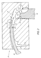
- An injection mold which can be seen in FIG. 2, is used to produce the blank 20 with a cavity 21, in which on the one hand a main slide 30 and on the other hand, an auxiliary slide 40 in the sense of the arrows shown in FIG. 2 Drive in 31, 41.
- the entry movements 31, 41 intersect and are in the Crossing point essentially perpendicular to each other.
- the headpiece 32 from The main slide 30 and the end area 42 of the auxiliary slide 40 are shown in FIG trained in a special way and interact with each other. At the Head piece 32 there are dome surfaces 33, while in the end area 42 has complementary mating coupling surfaces 43.
- the coupling surfaces 33 consist of one in the direction of the main slide 30 curved extension web 34 and from one to it parallel, short holding fingers 35.
- the mating coupling surfaces 43 are on a projection 44 pointing in the direction of retraction 41 of the auxiliary slide 40, which has a hook with a transverse hook opening 45.
- FIG. 3 shows the next phase.
- the projection 44 from the slider 40 is on the Side surface of the extension web 34 pushed by the main slide 30.
- this creates a guiding effect for the main slide 30.
- the Main slide 30 seated holding fingers 35 in the hook opening 45 and Hook head in the space between the extension web 34 and the Holding finger 35 penetrated.
- the coupling and mating coupling surfaces 33, 43 are in firm engagement with each other. This causes the main slide 30 from Auxiliary slide 40 held positively and in the correct position in the cavity Injection mold 40 supported.
- a molding compound 50 is placed in the injection mold 20 injected.
- a dot-dash line in FIG. 4 illustrated entry channel 52 enter the branch space 23.
- the Casting compound of course also gets into the tubular one in this way Cavity 22 and in the opposite side space 37 from the casting compound 50, the tube 12, which has already been mentioned several times, is produced.
- the aforementioned clutch engagement at 33, 43 and the exact result Support results over the entire pipe length 48, which of the whole Length of the handle shaft 11 corresponds to a defined tube wall thickness 49.
- Im Process step shown is this wall thickness 49 over the whole Pipe length 48 constant, which is why the dreaded sink marks in the emerging Handle shaft can not be formed in the inventive method. This ensures the uniform good appearance of the finished door handle.
- the injected casting masses 50 arise simultaneously with the pipe 12 the bearing approach 18 in the adjoining room 24, the actuator approach 19 in Branch room 23 and a limiting cam 38 in the opposite side room 37. All these parts 19, 18, 38 are produced in one piece with the tube 12, which is a very inexpensive manufacture of the blank 10 'guaranteed.
- Such a blank 10 ' can already be used as a simple door handle. in the In the present case, however, the blank 10 'becomes an "intelligent door handle" perfected, the finished state of which is shown in Fig. 9. The one there The procedural steps taking place are shown in the preceding FIGS. 5 to 8 clarified.
- Control electronics 60 are integrated in the blank 10 '. The Control electronics 60 acts when the door handle 10 is used with a lock and possibly together with other vehicle elements.
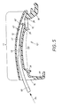
- the prepared control electronics 60 are first removed from the pipe entrance 14 5 inserted into the tube interior 13 in the sense of arrow 54 shown in FIG.
- the control electronics 60 goes out at least one multi-core cable 61, which expediently ends in contacts 62.
- the insertion movement ends when the control electronics 60 has reached the insertion position indicated in FIG. 6.
- the cable 61 protrudes with its contacts 62 out of the pipe outlet 15 out.
- the plug-in position of the control electronics 60 can not by End stops shown may be defined in the tube interior 13.
- the cable 61 is in a defined end position 61 ' brought and fixed in this.
- the inner surface 28 of the bearing shoulder is included a receptacle 56 protruding into the tube outlet 15.
- This consists, as can be seen particularly well from FIG. 1, of a groove 56 which is formed by a suitable profiling of the auxiliary slide 40 in the region of its flank 46 arises.
- the cable 61 is inserted into the groove in the direction of arrow 57 in FIG. 8 56 pressed in, in which the cable in the end position 61 'then gripped like a clip becomes. This facilitates further handling in the process.
- a filling material 55 or the like is Introduced. This will make the Position of the control electronics 60 and the end position 61 'of the cable finally secured. Filling with filler material 55 can take place to the extent that both the pipe entrance 14 and the pipe exit 15 are closed. Additionally or alternatively, the pipe entrance 14 and the pipe exit 15 could be closed by a lid, not shown.
- the door handle is known per se Way mounted on the door of the vehicle.
- the contacts 62 on Cable 61 'connected to associated mating contacts on the vehicle are provided.
- the pipe entrance 14 and the pipe exit 15 can be through a lid not shown are closed. This should also be the case take place when the cavity 13 of the door handle 10 remains empty, ie none Control electronics 60 is used there.
- whistling noises through the Airflow result, which are very annoying. For this reason it does not come only to close the pipe entrance 14 with such a cover, but also to connect the lid to the handle shaft 11 in a media-tight manner. The should be done on all sides in the joint area.
- a first one Possibility is the cover in the door entrance 14 and / or door exit 15 glue in.
- alien materials are used with regard to the Lid and handle. It seems simpler, the material from the lid and / or Handle 10 to use for the media-tight connection. This can e.g. by Heat welding happen according to claim 19 where the thermoplastic Properties can be temporarily liquefied by external heating. To the cooling of the merged materials results in the desired Media leaks.
- Types of materials of the lid and door handle 10 can be in advantageously also by ultrasonic welding or friction welding cause.
- laser welding is particularly important too, because when lasering or afterwards by control radiation, which also Laser light itself can be used to check the quality of the weld can. Such a check then ensures that the Desired media-tight connection between the cover and the door handle has been reached at the pipe entrance 14 or pipe entrance 15.
Landscapes
- Engineering & Computer Science (AREA)
- Manufacturing & Machinery (AREA)
- Mechanical Engineering (AREA)
- Lock And Its Accessories (AREA)
- Moulds For Moulding Plastics Or The Like (AREA)
- Injection Moulding Of Plastics Or The Like (AREA)
Applications Claiming Priority (2)
| Application Number | Priority Date | Filing Date | Title |
|---|---|---|---|
| DE10309446 | 2003-03-05 | ||
| DE2003109446 DE10309446A1 (de) | 2003-03-05 | 2003-03-05 | Verfahren zum Herstellen eines Türgriffs für Fahrzeuge |
Publications (2)
| Publication Number | Publication Date |
|---|---|
| EP1454731A1 true EP1454731A1 (fr) | 2004-09-08 |
| EP1454731B1 EP1454731B1 (fr) | 2006-05-03 |
Family
ID=32797802
Family Applications (1)
| Application Number | Title | Priority Date | Filing Date |
|---|---|---|---|
| EP20040005101 Expired - Lifetime EP1454731B1 (fr) | 2003-03-05 | 2004-03-04 | Procédé pour produire une poignée de porte pour véhicules |
Country Status (3)
| Country | Link |
|---|---|
| EP (1) | EP1454731B1 (fr) |
| DE (2) | DE10309446A1 (fr) |
| ES (1) | ES2259160T3 (fr) |
Cited By (10)
| Publication number | Priority date | Publication date | Assignee | Title |
|---|---|---|---|---|
| WO2007036378A1 (fr) * | 2005-09-26 | 2007-04-05 | Huf Hülsbeck & Fürst Gmbh & Co. Kg | Poignee de porte |
| FR2929841A1 (fr) * | 2008-04-14 | 2009-10-16 | Cie Euro Etude Rech Paroscopie | Anneau chirurgical implantable a boyau monobloc |
| DE102008036512A1 (de) * | 2008-06-19 | 2009-12-24 | Huf Hülsbeck & Fürst Gmbh & Co. Kg | Türaußengriff |
| WO2010057681A1 (fr) * | 2008-11-20 | 2010-05-27 | Huf Hülsbeck & Fürst Gmbh & Co. Kg | Poignée pour véhicule automobile |
| WO2010057999A1 (fr) * | 2008-11-20 | 2010-05-27 | Huf Hülsbeck & Fürst Gmbh & Co. Kg | Poignée de portière dotée de composants électroniques enrobés, et procédé de fabrication correspondant |
| WO2012059281A1 (fr) * | 2010-11-05 | 2012-05-10 | Huf Hülsbeck & Fürst Gmbh & Co. Kg | Poignée de porte, partie fonctionnelle et procédé d'introduction d'une matière de scellement dans la poignée de porte |
| DE102013114000A1 (de) * | 2013-12-13 | 2015-06-18 | Witte Automotive Gmbh | Verfahren zur Herstellung eines Türaußengriffs |
| CN107263809A (zh) * | 2017-08-02 | 2017-10-20 | 象山宁越模具有限公司 | 一种车门内把手模具及其模具的加工工艺 |
| DE102011053472B4 (de) | 2011-09-09 | 2022-08-18 | Huf Hülsbeck & Fürst Gmbh & Co. Kg | Elektronikmodul für eine Handhabe eines Fahrzeuges |
| CN120588438A (zh) * | 2025-08-06 | 2025-09-05 | 浙江鑫鼎塑业股份有限公司 | 一种防潮塑料狗粮桶的注塑模具 |
Families Citing this family (1)
| Publication number | Priority date | Publication date | Assignee | Title |
|---|---|---|---|---|
| DE102009057005A1 (de) | 2009-12-04 | 2011-06-09 | Audi Ag | Türgriff für eine Fahrzeugtür |
Citations (5)
| Publication number | Priority date | Publication date | Assignee | Title |
|---|---|---|---|---|
| US3152365A (en) * | 1961-08-22 | 1964-10-13 | Western Electric Co | Molding apparatus |
| JPS60161116A (ja) * | 1984-01-31 | 1985-08-22 | Kinjiyou Gomme Kk | ゴム製又は樹脂製の屈曲管接手の製法 |
| US5690884A (en) * | 1995-05-04 | 1997-11-25 | Kimberly-Clark Worldwide, Inc. | Method of injection molding a thin walled article |
| EP1067257A1 (fr) * | 1999-07-06 | 2001-01-10 | Valeo Sicurezza Abitacolo S.p.A. | Poignée de porte pour véhicule |
| WO2003050371A2 (fr) * | 2001-12-12 | 2003-06-19 | Witte-Velbert Gmbh & Co. Kg | Poignee, destinee en particulier a des portieres de vehicules automobiles |
Family Cites Families (1)
| Publication number | Priority date | Publication date | Assignee | Title |
|---|---|---|---|---|
| US6399006B1 (en) * | 2000-06-08 | 2002-06-04 | Entegris, Inc. | Process and apparatus for molding polymer sweep fittings |
-
2003
- 2003-03-05 DE DE2003109446 patent/DE10309446A1/de not_active Withdrawn
-
2004
- 2004-03-04 DE DE200450000480 patent/DE502004000480D1/de not_active Expired - Lifetime
- 2004-03-04 ES ES04005101T patent/ES2259160T3/es not_active Expired - Lifetime
- 2004-03-04 EP EP20040005101 patent/EP1454731B1/fr not_active Expired - Lifetime
Patent Citations (5)
| Publication number | Priority date | Publication date | Assignee | Title |
|---|---|---|---|---|
| US3152365A (en) * | 1961-08-22 | 1964-10-13 | Western Electric Co | Molding apparatus |
| JPS60161116A (ja) * | 1984-01-31 | 1985-08-22 | Kinjiyou Gomme Kk | ゴム製又は樹脂製の屈曲管接手の製法 |
| US5690884A (en) * | 1995-05-04 | 1997-11-25 | Kimberly-Clark Worldwide, Inc. | Method of injection molding a thin walled article |
| EP1067257A1 (fr) * | 1999-07-06 | 2001-01-10 | Valeo Sicurezza Abitacolo S.p.A. | Poignée de porte pour véhicule |
| WO2003050371A2 (fr) * | 2001-12-12 | 2003-06-19 | Witte-Velbert Gmbh & Co. Kg | Poignee, destinee en particulier a des portieres de vehicules automobiles |
Non-Patent Citations (1)
| Title |
|---|
| PATENT ABSTRACTS OF JAPAN vol. 0093, no. 26 (M - 441) 21 December 1985 (1985-12-21) * |
Cited By (16)
| Publication number | Priority date | Publication date | Assignee | Title |
|---|---|---|---|---|
| WO2007036378A1 (fr) * | 2005-09-26 | 2007-04-05 | Huf Hülsbeck & Fürst Gmbh & Co. Kg | Poignee de porte |
| DE102005046119B4 (de) * | 2005-09-26 | 2015-01-22 | Huf Hülsbeck & Fürst GmbH & Co KG | Türgriff |
| FR2929841A1 (fr) * | 2008-04-14 | 2009-10-16 | Cie Euro Etude Rech Paroscopie | Anneau chirurgical implantable a boyau monobloc |
| WO2009136122A3 (fr) * | 2008-04-14 | 2010-01-21 | Compagnie Europeenne D'etude Et De Recherche De Dispositifs Pour L'implantation Par Laparoscopie | Anneau chirurgical implantable a boyau monobloc |
| CN102066679A (zh) * | 2008-06-19 | 2011-05-18 | 胡夫·许尔斯贝克和福斯特有限及两合公司 | 门外部把手 |
| DE102008036512A1 (de) * | 2008-06-19 | 2009-12-24 | Huf Hülsbeck & Fürst Gmbh & Co. Kg | Türaußengriff |
| CN102066679B (zh) * | 2008-06-19 | 2013-11-13 | 胡夫·许尔斯贝克和福斯特有限及两合公司 | 门外部把手 |
| WO2010057681A1 (fr) * | 2008-11-20 | 2010-05-27 | Huf Hülsbeck & Fürst Gmbh & Co. Kg | Poignée pour véhicule automobile |
| DE102009009396A1 (de) | 2008-11-20 | 2010-05-27 | Huf Hülsbeck & Fürst Gmbh & Co. Kg | Türgriff mit vergossener Elektronikkomponente, sowie ein entsprechendes Fertigungsverfahren |
| DE102008059917A1 (de) | 2008-11-20 | 2010-05-27 | Huf Hülsbeck & Fürst Gmbh & Co. Kg | Handhabe für ein Kraftfahrzeug |
| WO2010057999A1 (fr) * | 2008-11-20 | 2010-05-27 | Huf Hülsbeck & Fürst Gmbh & Co. Kg | Poignée de portière dotée de composants électroniques enrobés, et procédé de fabrication correspondant |
| WO2012059281A1 (fr) * | 2010-11-05 | 2012-05-10 | Huf Hülsbeck & Fürst Gmbh & Co. Kg | Poignée de porte, partie fonctionnelle et procédé d'introduction d'une matière de scellement dans la poignée de porte |
| DE102011053472B4 (de) | 2011-09-09 | 2022-08-18 | Huf Hülsbeck & Fürst Gmbh & Co. Kg | Elektronikmodul für eine Handhabe eines Fahrzeuges |
| DE102013114000A1 (de) * | 2013-12-13 | 2015-06-18 | Witte Automotive Gmbh | Verfahren zur Herstellung eines Türaußengriffs |
| CN107263809A (zh) * | 2017-08-02 | 2017-10-20 | 象山宁越模具有限公司 | 一种车门内把手模具及其模具的加工工艺 |
| CN120588438A (zh) * | 2025-08-06 | 2025-09-05 | 浙江鑫鼎塑业股份有限公司 | 一种防潮塑料狗粮桶的注塑模具 |
Also Published As
| Publication number | Publication date |
|---|---|
| DE10309446A1 (de) | 2004-09-23 |
| EP1454731B1 (fr) | 2006-05-03 |
| ES2259160T3 (es) | 2006-09-16 |
| DE502004000480D1 (de) | 2006-06-08 |
Similar Documents
| Publication | Publication Date | Title |
|---|---|---|
| DE69216517T2 (de) | Doppellumiger Katheter | |
| EP2158820B1 (fr) | Brosse à dents et son procédé de fabrication | |
| EP1454731A1 (fr) | Procédé pour produire une poignée de porte pour véhicules | |
| EP1510383A2 (fr) | Glissière en matière plastique moulée | |
| DE3115579C2 (de) | Zweiteilige Gießform | |
| DE4033289A1 (de) | Motorisch einziehbares bandmass | |
| DE102011015522A1 (de) | Kunststoffkörper und Fertigungsanlage zur Herstellung eines Kunststoffkörpers | |
| DE29814418U1 (de) | Verschleißring für einen Kabelführungsschlauch eines Roboters | |
| EP0800907A1 (fr) | Buse à fermeture par aiguille avec moule d'injection et aiguille de fermeture | |
| DE3105217C2 (de) | Befestigungsvorrichtung an lösbar miteinander verbindbaren Beschlag- oder Ausstattungsteilen und Verfahren zur Herstellung derselben | |
| EP0706603B1 (fr) | Leve-glace a cable | |
| DE2202277B2 (de) | Vorrichtung zum Herstellen von Schreibstiftminen mit einem Kunststoffüberzug | |
| DE3338909C1 (de) | Katheteransatz | |
| DE102009008909B4 (de) | Sensoreinheit mit einem Schutzprofil | |
| EP0058391B1 (fr) | Dispositif de fixation sur des pièces de garnissage ou d'installation pouvant être reliées l'une à l'autre de manière amovible et procédé pour la fabrication d'un tel dispositif | |
| DE102007061106A1 (de) | Starter für eine Brennkraftmaschine sowie Verfahren zur Montage eines Starters | |
| DE10056260C1 (de) | Herstellung eines Spritzgußteils mit abgedichteten Ausnehmungen mit darinliegenden Hinterschnitten | |
| DE29923550U1 (de) | Elektrisch beheizter Schlauch für Scheibenwaschanlage | |
| AT406979B (de) | Verfahren zum auftragen eines thermoplastischen abstandhalters auf eine glasscheibe im zuge der herstellung von isolierglasscheiben und zum durchführen des verfahrens verwendbare düse | |
| DE2709542C2 (de) | Stapelbarer Kufenstuhl | |
| DE10131142C2 (de) | Verfahren zur Herstellung eines Kunststoffspritzgussteils, Werkzeug zur Herstellung des Kunststoffspritzgussteils und Kunststoffspritzgussteil | |
| DE19525000C1 (de) | Spritzgießwerkzeug zur Herstellung eines aus Kunststoff bestehenden Kastens | |
| DE10328445B4 (de) | Verfahren und Vorrichtung zur Herstellung von gedrehten Bürsten | |
| DE10353541B4 (de) | Verfahren und Vorrichtung zur Herstellung von Bürsten mit Borstenbündeln und Noppen | |
| DE102005004661B4 (de) | Verfahren und Maschine zum Herstellen von Bürsten |
Legal Events
| Date | Code | Title | Description |
|---|---|---|---|
| PUAI | Public reference made under article 153(3) epc to a published international application that has entered the european phase |
Free format text: ORIGINAL CODE: 0009012 |
|
| 17P | Request for examination filed |
Effective date: 20040703 |
|
| AK | Designated contracting states |
Kind code of ref document: A1 Designated state(s): AT BE BG CH CY CZ DE DK EE ES FI FR GB GR HU IE IT LI LU MC NL PL PT RO SE SI SK TR |
|
| AX | Request for extension of the european patent |
Extension state: AL LT LV MK |
|
| AKX | Designation fees paid |
Designated state(s): CZ DE ES FR GB IT |
|
| GRAP | Despatch of communication of intention to grant a patent |
Free format text: ORIGINAL CODE: EPIDOSNIGR1 |
|
| GRAS | Grant fee paid |
Free format text: ORIGINAL CODE: EPIDOSNIGR3 |
|
| GRAA | (expected) grant |
Free format text: ORIGINAL CODE: 0009210 |
|
| AK | Designated contracting states |
Kind code of ref document: B1 Designated state(s): CZ DE ES FR GB IT |
|
| PG25 | Lapsed in a contracting state [announced via postgrant information from national office to epo] |
Ref country code: IT Free format text: LAPSE BECAUSE OF FAILURE TO SUBMIT A TRANSLATION OF THE DESCRIPTION OR TO PAY THE FEE WITHIN THE PRESCRIBED TIME-LIMIT;WARNING: LAPSES OF ITALIAN PATENTS WITH EFFECTIVE DATE BEFORE 2007 MAY HAVE OCCURRED AT ANY TIME BEFORE 2007. THE CORRECT EFFECTIVE DATE MAY BE DIFFERENT FROM THE ONE RECORDED. Effective date: 20060503 Ref country code: GB Free format text: LAPSE BECAUSE OF FAILURE TO SUBMIT A TRANSLATION OF THE DESCRIPTION OR TO PAY THE FEE WITHIN THE PRESCRIBED TIME-LIMIT Effective date: 20060503 |
|
| REG | Reference to a national code |
Ref country code: GB Ref legal event code: FG4D Free format text: NOT ENGLISH |
|
| REF | Corresponds to: |
Ref document number: 502004000480 Country of ref document: DE Date of ref document: 20060608 Kind code of ref document: P |
|
| REG | Reference to a national code |
Ref country code: ES Ref legal event code: FG2A Ref document number: 2259160 Country of ref document: ES Kind code of ref document: T3 |
|
| ET | Fr: translation filed | ||
| GBV | Gb: ep patent (uk) treated as always having been void in accordance with gb section 77(7)/1977 [no translation filed] |
Effective date: 20060503 |
|
| PLBE | No opposition filed within time limit |
Free format text: ORIGINAL CODE: 0009261 |
|
| STAA | Information on the status of an ep patent application or granted ep patent |
Free format text: STATUS: NO OPPOSITION FILED WITHIN TIME LIMIT |
|
| 26N | No opposition filed |
Effective date: 20070206 |
|
| REG | Reference to a national code |
Ref country code: FR Ref legal event code: PLFP Year of fee payment: 12 |
|
| REG | Reference to a national code |
Ref country code: FR Ref legal event code: PLFP Year of fee payment: 13 |
|
| REG | Reference to a national code |
Ref country code: FR Ref legal event code: PLFP Year of fee payment: 14 |
|
| REG | Reference to a national code |
Ref country code: FR Ref legal event code: PLFP Year of fee payment: 15 |
|
| PGFP | Annual fee paid to national office [announced via postgrant information from national office to epo] |
Ref country code: FR Payment date: 20180319 Year of fee payment: 15 |
|
| PGFP | Annual fee paid to national office [announced via postgrant information from national office to epo] |
Ref country code: ES Payment date: 20180420 Year of fee payment: 15 |
|
| PGFP | Annual fee paid to national office [announced via postgrant information from national office to epo] |
Ref country code: IT Payment date: 20180330 Year of fee payment: 15 |
|
| PG25 | Lapsed in a contracting state [announced via postgrant information from national office to epo] |
Ref country code: FR Free format text: LAPSE BECAUSE OF NON-PAYMENT OF DUE FEES Effective date: 20190331 Ref country code: IT Free format text: LAPSE BECAUSE OF NON-PAYMENT OF DUE FEES Effective date: 20190304 |
|
| PGFP | Annual fee paid to national office [announced via postgrant information from national office to epo] |
Ref country code: DE Payment date: 20191217 Year of fee payment: 17 |
|
| PGFP | Annual fee paid to national office [announced via postgrant information from national office to epo] |
Ref country code: CZ Payment date: 20200224 Year of fee payment: 17 |
|
| REG | Reference to a national code |
Ref country code: ES Ref legal event code: FD2A Effective date: 20200724 |
|
| PG25 | Lapsed in a contracting state [announced via postgrant information from national office to epo] |
Ref country code: ES Free format text: LAPSE BECAUSE OF NON-PAYMENT OF DUE FEES Effective date: 20190305 |
|
| REG | Reference to a national code |
Ref country code: DE Ref legal event code: R119 Ref document number: 502004000480 Country of ref document: DE |
|
| PG25 | Lapsed in a contracting state [announced via postgrant information from national office to epo] |
Ref country code: CZ Free format text: LAPSE BECAUSE OF NON-PAYMENT OF DUE FEES Effective date: 20210304 |
|
| PG25 | Lapsed in a contracting state [announced via postgrant information from national office to epo] |
Ref country code: DE Free format text: LAPSE BECAUSE OF NON-PAYMENT OF DUE FEES Effective date: 20211001 |