EP1454767B1 - Reifen für hohe beanspruchungen - Google Patents
Reifen für hohe beanspruchungen Download PDFInfo
- Publication number
- EP1454767B1 EP1454767B1 EP02805011A EP02805011A EP1454767B1 EP 1454767 B1 EP1454767 B1 EP 1454767B1 EP 02805011 A EP02805011 A EP 02805011A EP 02805011 A EP02805011 A EP 02805011A EP 1454767 B1 EP1454767 B1 EP 1454767B1
- Authority
- EP
- European Patent Office
- Prior art keywords
- tread
- tire
- tread thickness
- belt ply
- thickness
- Prior art date
- Legal status (The legal status is an assumption and is not a legal conclusion. Google has not performed a legal analysis and makes no representation as to the accuracy of the status listed.)
- Expired - Lifetime
Links
- 239000011324 bead Substances 0.000 claims description 12
- 239000002184 metal Substances 0.000 claims description 5
- 230000008961 swelling Effects 0.000 description 4
- 230000002411 adverse Effects 0.000 description 3
- 230000000052 comparative effect Effects 0.000 description 3
- 230000000694 effects Effects 0.000 description 3
- 229910000831 Steel Inorganic materials 0.000 description 2
- 238000000034 method Methods 0.000 description 2
- 230000000452 restraining effect Effects 0.000 description 2
- 239000010959 steel Substances 0.000 description 2
- 238000010586 diagram Methods 0.000 description 1
- 230000002708 enhancing effect Effects 0.000 description 1
- 230000003014 reinforcing effect Effects 0.000 description 1
- 230000000717 retained effect Effects 0.000 description 1
Images


Classifications
-
- B—PERFORMING OPERATIONS; TRANSPORTING
- B60—VEHICLES IN GENERAL
- B60C—VEHICLE TYRES; TYRE INFLATION; TYRE CHANGING; CONNECTING VALVES TO INFLATABLE ELASTIC BODIES IN GENERAL; DEVICES OR ARRANGEMENTS RELATED TO TYRES
- B60C11/00—Tyre tread bands; Tread patterns; Anti-skid inserts
- B60C11/03—Tread patterns
- B60C11/0306—Patterns comprising block rows or discontinuous ribs
-
- B—PERFORMING OPERATIONS; TRANSPORTING
- B60—VEHICLES IN GENERAL
- B60C—VEHICLE TYRES; TYRE INFLATION; TYRE CHANGING; CONNECTING VALVES TO INFLATABLE ELASTIC BODIES IN GENERAL; DEVICES OR ARRANGEMENTS RELATED TO TYRES
- B60C11/00—Tyre tread bands; Tread patterns; Anti-skid inserts
-
- B—PERFORMING OPERATIONS; TRANSPORTING
- B60—VEHICLES IN GENERAL
- B60C—VEHICLE TYRES; TYRE INFLATION; TYRE CHANGING; CONNECTING VALVES TO INFLATABLE ELASTIC BODIES IN GENERAL; DEVICES OR ARRANGEMENTS RELATED TO TYRES
- B60C11/00—Tyre tread bands; Tread patterns; Anti-skid inserts
- B60C11/03—Tread patterns
- B60C11/04—Tread patterns in which the raised area of the pattern consists only of continuous circumferential ribs, e.g. zig-zag
-
- B—PERFORMING OPERATIONS; TRANSPORTING
- B60—VEHICLES IN GENERAL
- B60C—VEHICLE TYRES; TYRE INFLATION; TYRE CHANGING; CONNECTING VALVES TO INFLATABLE ELASTIC BODIES IN GENERAL; DEVICES OR ARRANGEMENTS RELATED TO TYRES
- B60C3/00—Tyres characterised by the transverse section
- B60C3/04—Tyres characterised by the transverse section characterised by the relative dimensions of the section, e.g. low profile
-
- B—PERFORMING OPERATIONS; TRANSPORTING
- B60—VEHICLES IN GENERAL
- B60C—VEHICLE TYRES; TYRE INFLATION; TYRE CHANGING; CONNECTING VALVES TO INFLATABLE ELASTIC BODIES IN GENERAL; DEVICES OR ARRANGEMENTS RELATED TO TYRES
- B60C9/00—Reinforcements or ply arrangement of pneumatic tyres
- B60C9/18—Structure or arrangement of belts or breakers, crown-reinforcing or cushioning layers
-
- B—PERFORMING OPERATIONS; TRANSPORTING
- B60—VEHICLES IN GENERAL
- B60C—VEHICLE TYRES; TYRE INFLATION; TYRE CHANGING; CONNECTING VALVES TO INFLATABLE ELASTIC BODIES IN GENERAL; DEVICES OR ARRANGEMENTS RELATED TO TYRES
- B60C9/00—Reinforcements or ply arrangement of pneumatic tyres
- B60C9/18—Structure or arrangement of belts or breakers, crown-reinforcing or cushioning layers
- B60C9/20—Structure or arrangement of belts or breakers, crown-reinforcing or cushioning layers built-up from rubberised plies each having all cords arranged substantially parallel
- B60C9/2003—Structure or arrangement of belts or breakers, crown-reinforcing or cushioning layers built-up from rubberised plies each having all cords arranged substantially parallel characterised by the materials of the belt cords
- B60C9/2006—Structure or arrangement of belts or breakers, crown-reinforcing or cushioning layers built-up from rubberised plies each having all cords arranged substantially parallel characterised by the materials of the belt cords consisting of steel cord plies only
-
- B—PERFORMING OPERATIONS; TRANSPORTING
- B60—VEHICLES IN GENERAL
- B60C—VEHICLE TYRES; TYRE INFLATION; TYRE CHANGING; CONNECTING VALVES TO INFLATABLE ELASTIC BODIES IN GENERAL; DEVICES OR ARRANGEMENTS RELATED TO TYRES
- B60C11/00—Tyre tread bands; Tread patterns; Anti-skid inserts
- B60C11/0008—Tyre tread bands; Tread patterns; Anti-skid inserts characterised by the tread rubber
- B60C2011/0016—Physical properties or dimensions
- B60C2011/0033—Thickness of the tread
Definitions
- the present invention relates to a heavy duty tire which uniforms wear by specifying a tread thickness from a second belt ply and carcass.
- a is formed into a single arc shape in a vulcanizing metal mold as schematically shown in Fig. 3 .
- document JP-A-7164823 Japanese Patent Application Laid-open No. H7-164823
- JP-A-7164823 Japanese Patent Application Laid-open No. H7-164823
- the outline of the tread in the vulcanizing metal mold is formed into a double radius shape in which a portion of the tread on the side of the tread grounding end is an arc having a greater radius of curvature than a portion of the tread on the side of the tire equator, thereby bringing the outline of the tread in the standard internal pressure state closer to the single arc to restrain the shoulder wear.
- Such a technique can restrain the shoulder wear in some degree but there is a problem that new shoulder wear is produced in the region Y. Especially when a circumferential groove is formed in the region Y, there is a tendency that so-called railway wears in which the groove side edge of the circumferential groove wears are seriously generated.
- the grounding surface shape has a correlation between a tread thickness from a second belt ply to a tread surface in a belt layer and a tread thickness from a carcass to the tread surface, and if each of the tread thickness is limited, the grounding surface shape could be optimized.
- An invention described in claim 1 of this application provides a heavy duty tire comprising a carcass extending from a tread portion to a bead core of a bead portion through a sidewall portion, and a belt layer having a first belt ply arranged inside the tread portion and outside the carcass and a second belt ply outside the first belt ply, wherein the second belt ply is curved in a form of projection of a single arc having a radius of curvature Rb of 450 to 700mm, when a tread thickness between an outline of a tread surface and the second belt ply is defined as T, a tread thickness minimum position Qt in which the tread thickness becomes a minimum value Tmin is provided in a region Y which is away from a tire equator C by a distance of 0.5 to 0.7 times of a tread grounding half width, a ratio Tmin/Tc between the minimum value Tmin and a tread thickness Tc at the position of the tire equator C is 0.92 to 0.97, and
- the term "tread grounding half width” means a distance between a tire equator C and a tire axially outer end (tread grounding end E) of a tread grounding surface which grounds when a standard load is applied to the tire in its standard internal pressure state in which the tire is assembled into a rim and a standard internal pressure is charged into the tire.
- standard rim is a rim whose specification are determined for each tire in the specification system including the specification based on the tire. For example,
- standard internal pressure is an air pressure whose specifications are determined for each tire, and the standard internal pressure is a maximum air pressure in the case of JATMA, the standard internal pressure is a maximum value described in "TIRE LOAD LIMITS AT VARIOUS COLD INFLATION PRESSURE" in the case of TRA, and the standard internal pressure is an "INFLATION PRESSURE” in the case of ETRTO. If the tire is for a passenger car, the standard internal pressure is 180kPa.
- the "standard internal pressure” is air pressure determined by the specifications for each tire, and the standard internal pressure is maximum load ability in the case of the JATMA, and the standard internal pressure is a maximum value described in a table "TIRE LOAD LIMITS AT VARIOUS COLD INFLATION PRESSURES" in the case of the TRA, and the and the standard internal pressure is "LOAD CAPACITY" in the case of the ETRTO.
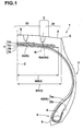
- Fig.1 is a sectional view of a heavy duty tire for a truck, a bus or the like according to the present invention
- Fig.2 is an enlarged view of a tread portion of the tire.
- a pneumatic tire 1 includes a carcass 6 extending from a tread portion 2 to a bead core 5 of a bead portion 4 through a sidewall portion 3, and a belt layer 7 disposed inside the tread portion 2 and outside the carcass 6.
- the carcass 6 is formed of one or more (one, in this example) of carcass ply 6A in which carcass cords are arranged at an angle of 70 to 90° with respect to a circumferential direction of the tire.
- Metal cords such as steel are preferable as the carcass cords.
- the carcass ply 6A includes ply bodies 6a and 6a extending between the bead cores 5 and 5, and folded-back portions 6b and 6b folded back and retained around the bead cores 5 and 5.
- a bead apex rubber 8 extending in a taper manner from the bead core 5 radially outward is disposed between the ply main body 6a and the folded-back portion 6b.
- the bead apex rubber 8 reinforces a portion of the tire from the bead portion 4 to the sidewall portion 3.
- the belt layer 7 is formed of three or more belt plies using metal cords as the belt cords.
- steel cords have four plies, i.e., a first belt ply 7A which is arranged at an angle of 60 ⁇ 15° with respect to the circumferential direction of the tire and disposed at innermost portion in the radial direction, and the second to the fourth belt plies 7B, 7C and 7D arranged at small angle of 10 to 35° with respect to the circumferential direction of the tire.
- the ply width in the tire axial direction of the first belt ply 7A is smaller than the ply width of the second belt ply 7B and is substantially equal to the ply width of the third belt ply 7C
- the ply width WB of the second belt ply 7B which has the maximum width is set to 0.80 to 0.95 times of the tread grounding width WT, thereby reinforcing substantially the entire width of the tread portion 2 with hooping effect, and enhancing the tread rigidity.
- the fourth belt ply 7D having the narrowest width functions as a breaker which protects the first to third belt plies 7A to 7C and carcass 6 from being injured outside.
- the tire 1 is provided with a tread pattern having two or more circumferential main grooves G which continuously extend in the circumferential direction.
- the circumferential main groove G has a width of 3mm or more, and extends in the circumferential direction in a straight or zigzag form.
- the circumferential main groove G comprises four grooves, i.e., inner circumferential main grooves Gi on opposite sides of the tire equator C, and outer circumferential main grooves Go on the outer sides.
- the outer circumferential main grooves Go constitute the outermost shoulder groove Gs in the tire axial direction.
- the groove center line N of the shoulder groove Gs passes through a region Y which is away from the tire equator C by a distance of 0.5 to 0.7 times of the tread grounding width WT/2.
- the tread portion 2 is divided into a tread center portion Jc at inner side of the shoulder groove Gs and a tread shoulder portion Js at outer side of the shoulder groove Gs.
- a center of the zigzag amplitude is defined as the groove center line N.
- a tread thickness T between an outline S (tread outline S, hereinafter) of the tread surface and the second belt ply 7B, and a tread thickness K from the tread outline S and the carcass 6 are specified as follows:
- the tread thicknesses T and K are increased from the tread thickness minimum positions Qt and Qk to the position of the tire equator C and the position of the second belt ply.
- the positions of the tread thickness minimum positions Qt and Qk may be different but in generally the positions are the same.
- the ratio Tmin/Tc in the tread thickness T is greater than 0.97, the effect for restraining the swelling tendency in the region Y is eliminated, and adversely if the ratio Tmin/Tc is smaller than 0.92, the grounding length in the region Y becomes excessively small, and railway wear is generated in the shoulder groove Gs.
- the ratio Tb/Tc in the tread thickness T is smaller than 0.95, the grounding length at the tread grounding end E becomes excessively small, the shoulder wear is generated. If the ratio Tb/Tc exceeds 1.10, adversely, the grounding length at the tread grounding end E becomes excessively great, the wear in the tread center portion Jc is increased, and there is a tendency that a so-called center wear is generated.
- the ratio Kmin/Kc is greater than 0.998, the effect for restraining the swelling which is prone to be generated in the region Y is eliminated, and adversely if the ratio Kmin/Kc is smaller than 0.97, the grounding length in the region Y is excessively small, and railway wear is generated in the shoulder groove Gs. If the ratio Kb/Kc is smaller than 1.2, the grounding length at the tread grounding end E becomes excessively small, the shoulder wear is generated. If the ratio Kb/Kc is greater than 1.50, the grounding length at the tread grounding end E becomes excessively great, the wear at the tread center portion Jc is increased, and there is a tendency that a so-called center wear is generated.
- the grounding surface shape is improved by the tread thicknesses T and K.
- the radius of curvature Rb of the second belt ply 7B is out from the above range, and when the second belt ply 7B is formed with a curved line other than the single arc, the correlation between the grounding surface shape and the tread thicknesses T, K becomes weak, the wear is not equalized sufficiently.
- the tread outline S in the tread center portion Jc is formed of a projecting arc outline S1 using a single arc or a plurality of arcs, and the tread outline S in the tread shoulder portion Js is formed of a substantially straight outline S2.
- Heavy duty tires having a structure shown in Fig. 1 and a size of 295/80R22.5 were prototyped based on specifications shown in Table 1, and uneven wear performance of the prototyped tires were tested, and the results are shown in Table 1.
- the grounding length shown in Table 1 is a length in the circumferential direction measured in the grounding surface shape when a standard load was applied to the tire in the standard internal pressure state in which the tire was assembled into the standard rim and a standard internal pressure was charged into the tire.
- a grounding length at the tire equator is L1
- a grounding length of the side edge of the groove on the side of the tire equator C of the shoulder groove Gs is L2
- a grounding length of the side line of the groove on the side of the grounding end of the shoulder groove Gs is L3
- a grounding length at the grounding end E is L4. If a variation in the grounding length is smaller, the uniformity of wear is higher and more excellent.
- the prototyped tires were mounted rims (22.5 ⁇ 8.25; having a rim width narrower than a standard rim by one rank) of all wheels of a truck (2-2•D type) under an internal pressure (900kPa), and the vehicle was allowed to run through a distance of 100,000km, and wear amounts at various positions were measured after running.
- a wear amount at the tire equator is defined as Z1
- a wear amount at the side line of the groove on the side of tire equator C of the shoulder groove Gs (in this example, a distance of 60mm from the tire equator) is defined as Z2
- a wear amount at the side line of groove on the side of the grounding end of the shoulder groove Gs (in this example, a distance of 76mm from the tire equator) is defined as Z3
- a wear amount at the grounding end E is defined as Z4.
- a tire of the present invention it is possible to improve the grounding surface shape by limiting the tread thickness from the second belt ply and the tread thickness from the carcass, and it is possible to enhance the uneven wear resistance performance and to equalize the wear.
Landscapes
- Engineering & Computer Science (AREA)
- Mechanical Engineering (AREA)
- Tires In General (AREA)
Claims (4)
- Schwerlastreifen (1), umfassend eine Karkasse (6), die sich von einem Laufflächenabschnitt (2) zu einem Wulstkern (5) eines Wulstabschnitts (4) durch einen Seitenwandabschnitt (3) erstreckt, und eine Gürtelschicht (7), die eine erste Gürtellage (7A), die innerhalb des Laufflächenabschnitts (2) und außerhalb der Karkasse (6) angeordnet ist, und eine zweite Gürtellage (7B) außerhalb der ersten Gürtellage (7A) aufweist,
dadurch gekennzeichnet, dass
die zweite Gürtellage (7B) in einer Form eines Vorsprungs mit einem einzigen Radius gekrümmt ist, der einen Krümmungsradius Rb von 450 bis 700 mm aufweist,
wenn eine Laufflächendicke zwischen einem Umriss einer Laufflächenoberfläche und der zweiten Gürtellage (7B) als T definiert ist, eine Position Qt eines Laufflächendickenminimums, an der die Laufflächendicke ein Minimalwert Tmin wird, in einem Bereich Y vorgesehen ist, der von dem Reifenäquator C eine Distanz des 0,5- bis 0,7-fachen einer Laufflächenbodenkontakthalbbreite entfernt ist, ein Verhältnis Tmin/Tc zwischen dem Minimalwert Tmin und einer Laufflächendicke Tc an der Position des Reifenäquators C 0,92 bis 0,97 beträgt, und ein Verhältnis Tb/Tc zwischen einer Laufflächendicke Tb an einer Position eines äußeren Endes der zweiten Gürtellage und der Laufflächendicke Tc 0,95 bis 1,10 beträgt, und
eine Laufflächendicke zwischen dem Umriss der Laufflächenoberfläche und der Karkasse (6) als K definiert ist, eine Position Qk eines Laufflächendickenminimums, an der die Laufflächendicke K ein Minimalwert Kmin wird, in dem Bereich Y vorgesehen ist, ein Verhältnis Kmin/Kc zwischen dem Minimalwert Kmin und einer Laufflächendicke Kc an der Position des Reifenäquators C 0,97 bis 0,998 beträgt, und ein Verhältnis Kb/Kc zwischen der Laufflächendicke Kb an einer Position des äußeren Endes der zweiten Gürtellage (7B) und der Laufflächendicke Kc 1,2 bis 1,5 beträgt. - Schwerlastreifen (1) nach Anspruch 1,
wobei die Laufflächendicken T und K von Positionen Qt, Qk des Laufflächendickenminimums zu einer Position des Reifenäquators C und einer Position des äußeren Endes der zweiten Gürtellage (7B) zunehmen. - Schwerlastreifen (1) nach Anspruch 1 oder 2,
wobei der Laufflächenabschnitt (2) zwei oder mehr Umfangshauptrillen (G) umfasst, die sich kontinuierlich in der Umfangsrichtung erstrecken, wobei eine Rillenmittellinie einer Schulterrille, die auf der äußersten Seite in der axialen Richtung des Reifens der Umfangshauptrillen angeordnet ist, durch den Bereich Y verläuft. - Schwerlastreifen (1) nach einem der Ansprüche 1 bis 3,
wobei ein Gürtelkord der Gürtellage (7) und ein Karkasskord der Karkasse (6) Metallkorde sind.
Applications Claiming Priority (3)
| Application Number | Priority Date | Filing Date | Title |
|---|---|---|---|
| JP2001382051 | 2001-12-14 | ||
| JP2001382051 | 2001-12-14 | ||
| PCT/JP2002/010496 WO2003051651A1 (en) | 2001-12-14 | 2002-10-09 | Heavy duty tire |
Publications (3)
| Publication Number | Publication Date |
|---|---|
| EP1454767A1 EP1454767A1 (de) | 2004-09-08 |
| EP1454767A4 EP1454767A4 (de) | 2008-03-05 |
| EP1454767B1 true EP1454767B1 (de) | 2008-11-05 |
Family
ID=19187405
Family Applications (1)
| Application Number | Title | Priority Date | Filing Date |
|---|---|---|---|
| EP02805011A Expired - Lifetime EP1454767B1 (de) | 2001-12-14 | 2002-10-09 | Reifen für hohe beanspruchungen |
Country Status (7)
| Country | Link |
|---|---|
| US (1) | US6880599B2 (de) |
| EP (1) | EP1454767B1 (de) |
| JP (1) | JP4015623B2 (de) |
| CN (1) | CN1276841C (de) |
| AU (1) | AU2002335238A1 (de) |
| DE (1) | DE60229771D1 (de) |
| WO (1) | WO2003051651A1 (de) |
Families Citing this family (23)
| Publication number | Priority date | Publication date | Assignee | Title |
|---|---|---|---|---|
| AU2002354498A1 (en) * | 2001-12-21 | 2003-07-09 | Sumitomo Rubber Industries, Ltd. | Heavy-duty tire |
| CN1304211C (zh) * | 2002-01-16 | 2007-03-14 | 住友橡胶工业株式会社 | 重载轮胎 |
| EP1759887B2 (de) * | 2004-06-23 | 2018-04-11 | Bridgestone Corporation | Luftreifen |
| US7784510B2 (en) * | 2005-10-17 | 2010-08-31 | Sumitomo Rubber Industries, Ltd. | Heavy duty tire having cap and base rubber layers, belt cushion rubber and sidewall rubber |
| US7503360B2 (en) * | 2005-12-15 | 2009-03-17 | The Goodyear Tire & Rubber Company | Radial farm tire for high clearance sprayers |
| EP2213480B1 (de) | 2007-10-23 | 2012-06-20 | The Yokohama Rubber Co., Ltd. | Luftreifen |
| FR2943951B1 (fr) * | 2009-04-07 | 2012-12-14 | Michelin Soc Tech | Pneumatique pour vehicules lourds comportant une couche d'elements de renforcement circonferentiels. |
| JP5559235B2 (ja) * | 2012-04-12 | 2014-07-23 | 住友ゴム工業株式会社 | 空気入りタイヤ |
| CN104379367B (zh) | 2012-07-13 | 2016-06-08 | 横滨橡胶株式会社 | 充气轮胎 |
| DE112012006990T5 (de) * | 2012-10-10 | 2015-06-18 | The Yokohama Rubber Co., Ltd. | Luftreifen |
| US10183531B2 (en) * | 2012-10-10 | 2019-01-22 | The Yokohama Rubber Co., Ltd. | Pneumatic tire |
| CN104703815B (zh) * | 2012-10-10 | 2016-12-28 | 横滨橡胶株式会社 | 充气轮胎 |
| WO2014103070A1 (ja) | 2012-12-28 | 2014-07-03 | 横浜ゴム株式会社 | 空気入りタイヤ |
| CN104884272B (zh) * | 2012-12-28 | 2017-04-12 | 横滨橡胶株式会社 | 充气轮胎 |
| DE112012007266B4 (de) * | 2012-12-28 | 2021-05-20 | The Yokohama Rubber Co., Ltd. | Luftreifen |
| KR101730944B1 (ko) * | 2012-12-28 | 2017-04-27 | 요코하마 고무 가부시키가이샤 | 공기입 타이어 |
| JP6623735B2 (ja) * | 2015-12-14 | 2019-12-25 | 住友ゴム工業株式会社 | 重荷重用空気入りタイヤ |
| JP6278090B1 (ja) * | 2016-10-11 | 2018-02-14 | 横浜ゴム株式会社 | 空気入りタイヤ |
| JP7215071B2 (ja) * | 2018-10-23 | 2023-01-31 | 横浜ゴム株式会社 | 空気入りタイヤ |
| CN109795263B (zh) * | 2019-02-13 | 2023-12-01 | 安徽佳通乘用子午线轮胎有限公司 | 一种优化的缺气保用半成品轮胎 |
| JP7363152B2 (ja) * | 2019-07-22 | 2023-10-18 | 住友ゴム工業株式会社 | 重荷重用空気入りタイヤ |
| JP7327071B2 (ja) * | 2019-10-11 | 2023-08-16 | 住友ゴム工業株式会社 | 重荷重用空気入りタイヤ |
| JP2021084520A (ja) * | 2019-11-27 | 2021-06-03 | 横浜ゴム株式会社 | タイヤ |
Family Cites Families (6)
| Publication number | Priority date | Publication date | Assignee | Title |
|---|---|---|---|---|
| JPH01141104A (ja) * | 1987-11-27 | 1989-06-02 | Sumitomo Rubber Ind Ltd | 重荷重用空気入りラジアルタイヤ |
| JP3121391B2 (ja) * | 1991-09-19 | 2000-12-25 | 株式会社ブリヂストン | 重荷重用空気入りタイヤ |
| US5647925A (en) * | 1993-12-17 | 1997-07-15 | Toyo Tire & Rubber Co., Ltd. | Pneumatic tire for heavy-loaded vehicles, with resistance to river wear |
| JP3343633B2 (ja) | 1993-12-17 | 2002-11-11 | 東洋ゴム工業株式会社 | 重荷重用空気入りタイヤ |
| JP3343634B2 (ja) * | 1993-12-17 | 2002-11-11 | 東洋ゴム工業株式会社 | 重荷重用空気入りタイヤ |
| JP3398730B2 (ja) | 1994-06-22 | 2003-04-21 | 東洋ゴム工業株式会社 | 重荷重用空気入りラジアルタイヤ |
-
2002
- 2002-10-09 EP EP02805011A patent/EP1454767B1/de not_active Expired - Lifetime
- 2002-10-09 DE DE60229771T patent/DE60229771D1/de not_active Expired - Lifetime
- 2002-10-09 US US10/468,040 patent/US6880599B2/en not_active Expired - Fee Related
- 2002-10-09 CN CNB028067541A patent/CN1276841C/zh not_active Expired - Fee Related
- 2002-10-09 JP JP2003552554A patent/JP4015623B2/ja not_active Expired - Fee Related
- 2002-10-09 AU AU2002335238A patent/AU2002335238A1/en not_active Abandoned
- 2002-10-09 WO PCT/JP2002/010496 patent/WO2003051651A1/ja not_active Ceased
Also Published As
| Publication number | Publication date |
|---|---|
| CN1276841C (zh) | 2006-09-27 |
| EP1454767A4 (de) | 2008-03-05 |
| JP4015623B2 (ja) | 2007-11-28 |
| DE60229771D1 (de) | 2008-12-18 |
| AU2002335238A1 (en) | 2003-06-30 |
| US6880599B2 (en) | 2005-04-19 |
| WO2003051651A1 (en) | 2003-06-26 |
| EP1454767A1 (de) | 2004-09-08 |
| JPWO2003051651A1 (ja) | 2005-04-28 |
| US20040069392A1 (en) | 2004-04-15 |
| CN1498171A (zh) | 2004-05-19 |
Similar Documents
| Publication | Publication Date | Title |
|---|---|---|
| US6880599B2 (en) | Heavy duty tire | |
| EP3424751B1 (de) | Luftreifen | |
| US7036541B2 (en) | Pneumatic tire | |
| EP2151333B1 (de) | Luftreifen | |
| EP3260308B1 (de) | Reifen | |
| EP3000621B1 (de) | Luftreifen | |
| EP2746066B1 (de) | Luftreifen | |
| EP3556573B1 (de) | Reifen | |
| EP2777949B1 (de) | Luftreifen | |
| EP3056359B1 (de) | Luftreifen | |
| CN103813913B (zh) | 充气轮胎 | |
| EP1466759B1 (de) | Hochleistungsreifen | |
| EP1459909B1 (de) | Hochleistungsreifen | |
| EP2979900B1 (de) | Schwerlastluftreifen | |
| EP2581238A1 (de) | Schwerlastreifen | |
| EP1712377A1 (de) | Luftreifen | |
| EP3023266B1 (de) | Luftreifen | |
| EP2275285B1 (de) | Luftreifen | |
| EP2402176B1 (de) | Luftreifen für ein zweirädriges kraftfahrzeug | |
| JP3808778B2 (ja) | 重荷重用タイヤ | |
| EP2213480B1 (de) | Luftreifen | |
| EP4420897B1 (de) | Reifen | |
| CN116353255B (zh) | 轮胎 | |
| EP3251876B1 (de) | Luftreifen | |
| JP4687342B2 (ja) | 空気入りタイヤ |
Legal Events
| Date | Code | Title | Description |
|---|---|---|---|
| PUAI | Public reference made under article 153(3) epc to a published international application that has entered the european phase |
Free format text: ORIGINAL CODE: 0009012 |
|
| 17P | Request for examination filed |
Effective date: 20030918 |
|
| AK | Designated contracting states |
Kind code of ref document: A1 Designated state(s): AT BE BG CH CY CZ DE DK EE ES FI FR GB GR IE IT LI LU MC NL PT SE SK TR |
|
| AX | Request for extension of the european patent |
Extension state: AL LT LV MK RO SI |
|
| A4 | Supplementary search report drawn up and despatched |
Effective date: 20080131 |
|
| GRAP | Despatch of communication of intention to grant a patent |
Free format text: ORIGINAL CODE: EPIDOSNIGR1 |
|
| GRAS | Grant fee paid |
Free format text: ORIGINAL CODE: EPIDOSNIGR3 |
|
| GRAA | (expected) grant |
Free format text: ORIGINAL CODE: 0009210 |
|
| AK | Designated contracting states |
Kind code of ref document: B1 Designated state(s): DE FR GB |
|
| REG | Reference to a national code |
Ref country code: GB Ref legal event code: FG4D |
|
| REF | Corresponds to: |
Ref document number: 60229771 Country of ref document: DE Date of ref document: 20081218 Kind code of ref document: P |
|
| PLBE | No opposition filed within time limit |
Free format text: ORIGINAL CODE: 0009261 |
|
| STAA | Information on the status of an ep patent application or granted ep patent |
Free format text: STATUS: NO OPPOSITION FILED WITHIN TIME LIMIT |
|
| 26N | No opposition filed |
Effective date: 20090806 |
|
| PGFP | Annual fee paid to national office [announced via postgrant information from national office to epo] |
Ref country code: FR Payment date: 20141008 Year of fee payment: 13 Ref country code: GB Payment date: 20141008 Year of fee payment: 13 Ref country code: DE Payment date: 20140930 Year of fee payment: 13 |
|
| REG | Reference to a national code |
Ref country code: DE Ref legal event code: R119 Ref document number: 60229771 Country of ref document: DE |
|
| GBPC | Gb: european patent ceased through non-payment of renewal fee |
Effective date: 20151009 |
|
| PG25 | Lapsed in a contracting state [announced via postgrant information from national office to epo] |
Ref country code: DE Free format text: LAPSE BECAUSE OF NON-PAYMENT OF DUE FEES Effective date: 20160503 Ref country code: GB Free format text: LAPSE BECAUSE OF NON-PAYMENT OF DUE FEES Effective date: 20151009 |
|
| REG | Reference to a national code |
Ref country code: FR Ref legal event code: ST Effective date: 20160630 |
|
| PG25 | Lapsed in a contracting state [announced via postgrant information from national office to epo] |
Ref country code: FR Free format text: LAPSE BECAUSE OF NON-PAYMENT OF DUE FEES Effective date: 20151102 |