EP1454870A2 - Aufhängung für Lasthaken - Google Patents
Aufhängung für Lasthaken Download PDFInfo
- Publication number
- EP1454870A2 EP1454870A2 EP04004899A EP04004899A EP1454870A2 EP 1454870 A2 EP1454870 A2 EP 1454870A2 EP 04004899 A EP04004899 A EP 04004899A EP 04004899 A EP04004899 A EP 04004899A EP 1454870 A2 EP1454870 A2 EP 1454870A2
- Authority
- EP
- European Patent Office
- Prior art keywords
- suspension according
- bearing
- ring
- load hook
- receiving ring
- Prior art date
- Legal status (The legal status is an assumption and is not a legal conclusion. Google has not performed a legal analysis and makes no representation as to the accuracy of the status listed.)
- Granted
Links
- 239000000725 suspension Substances 0.000 title claims abstract description 37
- 230000003716 rejuvenation Effects 0.000 description 3
- 238000005266 casting Methods 0.000 description 2
- 238000010276 construction Methods 0.000 description 2
- 238000004519 manufacturing process Methods 0.000 description 2
- 230000015572 biosynthetic process Effects 0.000 description 1
- 238000005516 engineering process Methods 0.000 description 1
- 238000003780 insertion Methods 0.000 description 1
- 230000037431 insertion Effects 0.000 description 1
Images


Classifications
-
- B—PERFORMING OPERATIONS; TRANSPORTING
- B66—HOISTING; LIFTING; HAULING
- B66C—CRANES; LOAD-ENGAGING ELEMENTS OR DEVICES FOR CRANES, CAPSTANS, WINCHES, OR TACKLES
- B66C1/00—Load-engaging elements or devices attached to lifting or lowering gear of cranes or adapted for connection therewith for transmitting lifting forces to articles or groups of articles
- B66C1/10—Load-engaging elements or devices attached to lifting or lowering gear of cranes or adapted for connection therewith for transmitting lifting forces to articles or groups of articles by mechanical means
- B66C1/22—Rigid members, e.g. L-shaped members, with parts engaging the under surface of the loads; Crane hooks
- B66C1/34—Crane hooks
Definitions
- the invention relates to a suspension for load hook, in particular for Bottoms of cables, with one in a recess of a supporting body to a vertical axis rotatably mounted shaft, which, in one Through hole of a support member mounted over at least one Axial bearing supported on the support body.
- Suspensions for load hooks are from practice in the most varied Embodiments known. From DIN 15 411 is a lower bottle with two Pulleys are known in which the load hook around a vertical and a horizontal Axis is rotatably mounted on a load hook suspension, below the the Cable pulleys bearing connecting body is arranged. Due to the use on the one hand the connecting body and on the other hand the separate load hook suspension This known construction has a relatively large height and also many components on.
- a generic load hook suspension is known from German patent DE 196 02 931 C2 known.
- the shaft of the load hook is in one Recess of the pulleys bearing connecting body of a lower bottle stored.
- the inserted into the recess and the shaft of the load hook superimposed thrust bearing is tangentially extending screws in the recess held by the pulleys ago in Tangentialnuten the bearing cage be screwed.
- This tangential screwing of the thrust bearing in the recess is the mounting of this known suspension very expensive and since it is an exact positioning of the bearing cage with the stored therein Loading hook in the recess of the connecting body requires because the Tangential screws only in one position fixing into the tangential grooves of the Bearing cage can be screwed.
- the present invention seeks to provide a short-building and to create a simple suspension for a load hook.
- the shaft of the load hook on a from the support element, the at least one thrust bearing and a ring surrounding the shaft Receiving ring existing bearing assembly is mounted in the support body, wherein the bearing arrangement, preferably the receiving ring, via a securing element, in particular a snap ring, is fixed in the support body.
- the storage according to the invention allows the entire bearing arrangement to pre-assemble the insertion in the recess of the support body. About that In addition, it only needs to set the bearing assembly in the recess a fuse element, such as a snap ring. The assembly is thus easy and quick to carry out, especially since there is no special positioning requires the bearing assembly to the support body and / or the recess.
- the securing element for Securing the bearing assembly on the one hand an undercut of the support body engages behind and on the other hand rests against a contact surface of the receiving ring.
- the entire bearing assembly stored in this embodiment on the on Supporting body supporting securing element.
- the Undercut for receiving the securing element as a circumferential annular groove formed in the support body.
- the setting of the load hook shaft on the support element is carried out according to a preferred embodiment of the invention via a securing element, in particular a snap ring, the one hand in the mounted state Undercut at the free end of the shaft engages behind and on the other hand in one Deepening of the support element is arranged.
- a securing element in particular a snap ring
- the thrust bearing facing surface of the support element and / or the receiving ring as a plane contact surface for the particular as Axial needle bearing trained thrust bearing formed.
- the support element forms even the upper bearing shell of the thrust bearing, reducing the number of components can be further reduced.
- the Load hook in addition to the twistability about the vertical axis by one horizontal axis is pivotally mounted in the support body. Through this additional degree of freedom can be the handling and use significantly increase a load hook mounted according to the invention.
- This Pivotability about a horizontal axis is advantageously by two between the lower bearing shell of the thrust bearing and the receiving ring arranged cylindrical rollers achieved, which form the horizontal pivot axis, wherein the cylindrical rollers opposite each other on both sides of the shank of Load hooks are arranged in the bearing assembly.
- the number of the formation of the bearing assembly according to the invention necessary components can be further reduced that the Cylindrical rollers between the receiving ring and a lower bearing shell of the Thrust bearing forming the shaft annularly surrounding pivot bearing ring are arranged.
- the pivoting about the horizontal axis can be facilitated and also in the Verschwenkwinkel is limited, that on the one hand in a plane perpendicular to the Pivot axis between the mutually facing surfaces of the receiving ring and the pivot bearing ring is formed a gap and on the other hand the Side walls of the through hole of the receiving ring at least in the The pivoting plane of the load hook is conically widened in the direction of the load hook are formed.
- the limitation of the pivoting angle is made possible by the fact that the facing surfaces of the receiving ring and the pivot bearing ring and / or the conical side walls of the through hole of the receiving ring form the pivoting angle of the load hook limiting stop surfaces.
- the gap between the facing surfaces of the receiving ring and the pivot bearing ring is advantageously in radially outward pointing direction widening trained.
- the handling of the load hook provided device facilitating at least one recessed grip formed in the support body.
- a connecting body of a Bottom trained and provided with the at least one recessed grip Support body is easy and inexpensive to manufacture as a casting
- a with Handholds provided with forged load hook as he from the state of Technology is known, represents a complex and expensive to manufacture special component.
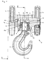
- FIG. 1 to Figure 5 show two embodiments of the Embodiment of the suspension of a load hook 1, which in a recess. 2 a supporting body 3 is mounted.
- the supporting body 3 as two pulleys 4 a lower block 5 supporting Formed connecting body.
- This fuse element 12 can, as in the figures, Figure 1 to Figure 5 represented, for example, be designed as a snap ring, the one Undercut 13, in particular an annular groove in the support body 3 engages behind.
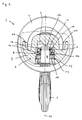
- FIG. 2 The sectional side view of Figure 2 it can be seen that the Facilitation of handling in the support body 3 recessed grips 17 are formed.
- the Training the recessed grips 17 on the support body 3 is particularly advantageous because a provided with recessed grips 17 supporting body 3 simple and inexpensive than Casting is to be finished, while a forged grips 17 forged Load hook 1, as known from the prior art, a complex and represents expensive to be manufactured special component.
- the pivot bearing ring 20 the bearing shells of the thrust bearing 8
- the Thrust bearing 8 had its own storage cage.
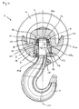
- FIGs 4 and 5 is a concrete embodiment of the Swivel bearing ring 20 and the receiving ring 10 can be seen by the The load hook 1, on the one hand, can easily be pivoted about the axis 18, on the other hand also the pivot angle can be limited.
- side walls 10b are through-holes of the receiving ring 10 at least in the pivoting plane of the load hook 1 in the direction of the load hook. 1 is formed conically widened to the pivoting of the load hook 1 to enable.
- the mutually facing contact surfaces 10a, 20a of the receiving ring 10 and the Swivel bearing ring 20 and / or the conical side walls 10b of the receiving ring 10 thus form the pivot angle of the load hook 1 limiting Stop surfaces.
- Such trained suspensions for hooks 1 are on the one hand by their compact design with low height and wise on the other the advantage that the entire bearing assembly 6 outside the support body. 3 can be pre-assembled. For the actual assembly on the support body 3 is required Finally, only the onset of the shaft 9 of the load hook. 1 preassembled bearing assembly 6 in the recess 2 in the support body 3 and the Fixing the bearing assembly 6 via the securing element 12 on the support body Third
Landscapes
- Engineering & Computer Science (AREA)
- Mechanical Engineering (AREA)
- Hooks, Suction Cups, And Attachment By Adhesive Means (AREA)
- Load-Engaging Elements For Cranes (AREA)
- Rolling Contact Bearings (AREA)
- Vehicle Body Suspensions (AREA)
- Supports Or Holders For Household Use (AREA)
- Snaps, Bayonet Connections, Set Pins, And Snap Rings (AREA)
Abstract
Description
- Figur 1
- eine teilweise geschnittene Vorderansicht einer an einer Unterflasche angeordneten Lasthaken-Aufhängung gemäß einer ersten erfindungsgemäßen Ausführungsform;
- Figur 2
- einen Schnitt entlang der Linie II-II gemäß Figur 1;
- Figur 3
- eine teilweise geschnittene Vorderansicht einer an einer Unterflasche angeordneten Lasthaken-Aufhängung gemäß einer zweiten erfindungsgemäßen Ausführungsform;
- Figur 4
- einen Schnitt entlang der Linie IV-IV gemäß Figur 3 und
- Figur 5
- eine Ansicht gemäß Figur 4, jedoch den Lasthaken in einer verschwenkten Position darstellend.
- 1
- Lasthaken
- 2
- Ausnehmung
- 3
- Tragkörper
- 4
- Seilrolle
- 5
- Unterflasche
- 6
- Lageranordnung
- 7
- Abstützelement
- 7a
- Anlagefläche
- 8
- Axiallager
- 9
- Schaft
- 10
- Aufnahmering
- 10a
- Anlagefläche
- 10b
- Seitenwand
- 11
- Achse (Drehachse)
- 12
- Sicherungselement
- 13
- Hinterschneidung
- 14
- Sicherungselement
- 15
- Hinterschneidung
- 15a
- Ringnut
- 15b
- Verjüngung
- 16
- Vertiefung
- 17
- Griffmulde
- 18
- Achse (Schwenkachse)
- 19
- Zylinderrolle
- 20
- Schwenklagerring
- 20a
- Anlagefläche
- 21
- Spalt
Claims (18)
- Aufhängung für Lasthaken, insbesondere für Unterflaschen von Seilzügen, mit einem in einer Ausnehmung (2) eines Tragkörpers (3) um eine vertikale Achse (11) drehbar gelagerten Schaft (9), der sich, in einer Durchgangsbohrung eines Abstützelements (7) gelagert, über mindestens ein Axiallager (8) am Tragkörper (3) abstützt,
dadurch gekennzeichnet, dass der Schaft (9) des Lasthakens (1) über eine aus dem Abstützelement (7), dem mindestens einen Axiallager (8) sowie einem den Schaft (9) ringförmig umgebenden Aufnahmering (10) bestehende Lageranordnung (6) in dem Tragkörper (3) gelagert ist, wobei die Lageranordnung (6) über ein Sicherungselement (12), insbesondere einen Sprengring, im Tragkörper (3) festgelegt ist. - Aufhängung nach Anspruch 1, dadurch gekennzeichnet, dass der Aufnahmering (10) über ein Sicherungselement (12) im Tragkörper (3) festgelegt ist.
- Aufhängung nach Anspruch 1 oder 2, dadurch gekennzeichnet, dass das Sicherungselement (12) zur Sicherung der Lageranordnung (6) einerseits eine Hinterschneidung (13) des Tragkörpers (3) hintergreift und andererseits an einer Anlagefläche des Aufnahmerings (10) anliegt.
- Aufhängung nach Anspruch 3, dadurch gekennzeichnet, dass die Hinterschneidung (13) im Tragkörper (3) zur Aufnahme des Sicherungselements (12) als umlaufende Ringnut ausgebildet ist.
- Aufhängung nach mindestens einem der Ansprüche 1 bis 4, dadurch gekennzeichnet, dass der Schaft (9) des Lasthakens (1) über ein Sicherungselement (14), insbesondere einen Sprengring, am Abstützelement (7) festgelegt ist, das im montierten Zustand einerseits eine Hinterschneidung (15) am freien Ende des Schaftes (9) hintergreift und andererseits in einer Vertiefung (16) des Abstützelements (7) angeordnet ist.
- Aufhängung nach Anspruch 5, dadurch gekennzeichnet, dass die Hinterschneidung (15) zur Aufnahme des Sicherungselements (14) als umlaufende Ringnut (15a) ausgebildet ist.
- Aufhängung nach Anspruch 5, dadurch gekennzeichnet, dass die Hinterschneidung (15) zur Aufnahme des Sicherungselements (14) als vom freien Ende des Schaftes (9) fortweisende Verjüngung (15b) des Schaftquerschnittes ausgebildet ist.
- Aufhängung nach mindestens einem der Ansprüche 1 bis 7, dadurch gekennzeichnet, dass das Abstützelement (7) und/oder der Aufnahmering (10) eine plane Anlagefläche (7a, 10a) für das insbesondere als Axialnadellager ausgebildete Axiallager (8) aufweisen.
- Aufhängung nach mindestens einem der Ansprüche 1 bis 7, dadurch gekennzeichnet, dass das Abstützelement (7) die obere Lagerschale des Axiallagers (8) bildet.
- Aufhängung nach mindestens einem der Ansprüche 1 bis 9, dadurch gekennzeichnet, dass der Lasthaken (1) zusätzlich um eine horizontale Achse (18) verschwenkbar im Tragkörper (3) gelagert ist.
- Aufhängung nach Anspruch 10, dadurch gekennzeichnet, dass zwei zwischen der unteren Lagerschale des Axiallagers (8) und dem Aufnahmering (10) angeordnete Zylinderrollen (19) die horizontale Schwenkachse (18) bilden, wobei die Zylinderrollen (19) einander gegenüberliegend beidseitig des Schaftes (9) des Lasthakens (1) in der Lageranordnung (6) angeordnet sind.
- Aufhängung nach Anspruch 11, dadurch gekennzeichnet, dass die Zylinderrollen (19) zwischen dem Aufnahmering (10) und einem die untere Lagerschale des Axiallagers (8) bildenden, den Schaft (9) ringförmig umgebenden Schwenklagerring (20) angeordnet sind.
- Aufhängung nach Anspruch 12, dadurch gekennzeichnet, dass in einer Ebene rechtwinklig zur Schwenkachse (18) zwischen den einander zugewandten Flächen (10a, 20a) des Aufnahmerings (10) und des Schwenklagerrings (20) ein Spalt (21) ausgebildet ist.
- Aufhängung nach Anspruch 13, dadurch gekennzeichnet, dass der Spalt (21) sich in radial nach außen weisender Richtung erweiternd ausgebildet ist.
- Aufhängung nach mindestens einem der Ansprüche 11 bis 14, dadurch gekennzeichnet, dass Seitenwände (10b) der Durchgangsbohrung des Aufnahmerings (10) zumindest in der Verschwenkebene des Lasthakens (1) in Richtung zum Lasthaken (1) konisch erweitert ausgebildet sind.
- Aufhängung nach mindestens einem der Ansprüche 11 bis 15, dadurch gekennzeichnet, dass die einander zugewandten Flächen (10a, 20a) des Aufnahmerings (10) und des Schwenklagerrings (20) und/oder die konischen Seitenwände (10b) des Aufnahmerings (10) den Verschwenkwinkel des Lasthakens (1) begrenzende Anschlagflächen bilden.
- Aufhängung nach mindestens einem der Ansprüche 1 bis 16, dadurch gekennzeichnet, dass im Tragkörper (3) mindestens eine Griffmulde (17) ausgebildet ist.
- Aufhängung nach mindestens einem der Ansprüche 1 bis 17, dadurch gekennzeichnet, dass der Tragkörper (3) ein zwei Seilrollen (4) einer Unterflasche (5) tragender Verbindungskörper ist.
Applications Claiming Priority (2)
| Application Number | Priority Date | Filing Date | Title |
|---|---|---|---|
| DE10310087A DE10310087A1 (de) | 2003-03-06 | 2003-03-06 | Aufhängung für Lasthaken |
| DE10310087 | 2003-03-06 |
Publications (3)
| Publication Number | Publication Date |
|---|---|
| EP1454870A2 true EP1454870A2 (de) | 2004-09-08 |
| EP1454870A3 EP1454870A3 (de) | 2004-10-06 |
| EP1454870B1 EP1454870B1 (de) | 2011-01-19 |
Family
ID=32797877
Family Applications (1)
| Application Number | Title | Priority Date | Filing Date |
|---|---|---|---|
| EP04004899A Expired - Lifetime EP1454870B1 (de) | 2003-03-06 | 2004-03-03 | Aufhängung für Lasthaken |
Country Status (6)
| Country | Link |
|---|---|
| US (1) | US7219937B2 (de) |
| EP (1) | EP1454870B1 (de) |
| CN (1) | CN100402405C (de) |
| AT (1) | ATE495997T1 (de) |
| DE (2) | DE10310087A1 (de) |
| ES (1) | ES2358796T3 (de) |
Cited By (3)
| Publication number | Priority date | Publication date | Assignee | Title |
|---|---|---|---|---|
| US7607707B2 (en) | 2005-12-24 | 2009-10-27 | Demag Cranes & Components Gmbh | Load hook |
| US8608215B2 (en) | 2009-04-11 | 2013-12-17 | Demag Cranes & Components Gmbh | Load-receiving means, in particular a hook block of a lifting gear |
| EP2706032A1 (de) * | 2012-09-11 | 2014-03-12 | RIW-Maschinenbau GmbH | Lastaufnahmevorrichtung, insbesondere Unterflasche für ein Hebezeug |
Families Citing this family (5)
| Publication number | Priority date | Publication date | Assignee | Title |
|---|---|---|---|---|
| EP2388227B1 (de) * | 2010-05-20 | 2015-01-21 | Rotzler Gmbh + Co. Kg | Kranhaken mit einer Hakengewichtsanordnung |
| DE102011054148B4 (de) * | 2011-10-04 | 2015-10-22 | Terex Mhps Gmbh | Lastaufnahmemittel, insbesondere Lasthaken |
| CN102701094A (zh) * | 2012-06-28 | 2012-10-03 | 河南省黄河防爆起重机有限公司 | 钢丝绳纽绕应力释放机构 |
| US10280055B2 (en) * | 2017-05-02 | 2019-05-07 | William von Eberstein | Ball joint lifting assembly and method |
| CN109437027B (zh) * | 2018-12-19 | 2023-09-26 | 厦门厦工中铁重型机械有限公司 | 一种盾构机刀具吊装装置 |
Citations (3)
| Publication number | Priority date | Publication date | Assignee | Title |
|---|---|---|---|---|
| DE882606C (de) | 1951-05-12 | 1953-07-09 | Heuer Hammer Schwerschmieden B | Haken |
| DE19817011A1 (de) | 1998-04-17 | 1999-10-28 | Stahl R Foerdertech Gmbh | Seilhakenanordnung |
| DE19602931C2 (de) | 1996-01-18 | 2001-04-26 | Mannesmann Ag | Unterflasche |
Family Cites Families (12)
| Publication number | Priority date | Publication date | Assignee | Title |
|---|---|---|---|---|
| DE725114C (de) * | 1939-09-27 | 1942-09-14 | Maschb Act Ges Vorm Beck & Hen | Lasthaken fuer Krane o. dgl. |
| FR920416A (fr) * | 1945-09-28 | 1947-04-08 | Dispositif d'attache de câble pour appareils de levage et autres applications | |
| US2625005A (en) * | 1947-06-12 | 1953-01-13 | Keller Tool Co | Hoist hook assembly |
| US2500459A (en) * | 1948-05-24 | 1950-03-14 | William S Hoover | Work supporting attachment for hoists |
| US2823944A (en) * | 1955-08-18 | 1958-02-18 | Heppenstall Co | Movable load supporting device |
| SE410214B (sv) * | 1978-04-11 | 1979-10-01 | Bergs Smide Ab K A | Kullagerlekare |
| US4708382A (en) * | 1987-01-20 | 1987-11-24 | Cooper Industries | Separable lifting hook |
| DD274806A1 (de) * | 1988-08-12 | 1990-01-03 | Freiberger Zellstoff Papier | Hakentraverse fuer doppelhaken |
| CN2199971Y (zh) * | 1993-02-09 | 1995-06-07 | 刘永德 | 刚性吊钩组 |
| CN2176352Y (zh) * | 1993-12-11 | 1994-09-07 | 张玉锦 | 新型封闭式吊钩装置 |
| CN2218170Y (zh) * | 1994-11-23 | 1996-01-24 | 钟宗勇 | 锤重吊钩头 |
| CN2516519Y (zh) * | 2002-01-17 | 2002-10-16 | 徐建 | 新型封闭式吊钩 |
-
2003
- 2003-03-06 DE DE10310087A patent/DE10310087A1/de not_active Withdrawn
-
2004
- 2004-03-03 EP EP04004899A patent/EP1454870B1/de not_active Expired - Lifetime
- 2004-03-03 AT AT04004899T patent/ATE495997T1/de active
- 2004-03-03 US US10/792,188 patent/US7219937B2/en not_active Expired - Lifetime
- 2004-03-03 DE DE502004012117T patent/DE502004012117D1/de not_active Expired - Lifetime
- 2004-03-03 ES ES04004899T patent/ES2358796T3/es not_active Expired - Lifetime
- 2004-03-05 CN CNB2004100077828A patent/CN100402405C/zh not_active Expired - Fee Related
Patent Citations (3)
| Publication number | Priority date | Publication date | Assignee | Title |
|---|---|---|---|---|
| DE882606C (de) | 1951-05-12 | 1953-07-09 | Heuer Hammer Schwerschmieden B | Haken |
| DE19602931C2 (de) | 1996-01-18 | 2001-04-26 | Mannesmann Ag | Unterflasche |
| DE19817011A1 (de) | 1998-04-17 | 1999-10-28 | Stahl R Foerdertech Gmbh | Seilhakenanordnung |
Cited By (3)
| Publication number | Priority date | Publication date | Assignee | Title |
|---|---|---|---|---|
| US7607707B2 (en) | 2005-12-24 | 2009-10-27 | Demag Cranes & Components Gmbh | Load hook |
| US8608215B2 (en) | 2009-04-11 | 2013-12-17 | Demag Cranes & Components Gmbh | Load-receiving means, in particular a hook block of a lifting gear |
| EP2706032A1 (de) * | 2012-09-11 | 2014-03-12 | RIW-Maschinenbau GmbH | Lastaufnahmevorrichtung, insbesondere Unterflasche für ein Hebezeug |
Also Published As
| Publication number | Publication date |
|---|---|
| ATE495997T1 (de) | 2011-02-15 |
| ES2358796T3 (es) | 2011-05-13 |
| EP1454870B1 (de) | 2011-01-19 |
| US7219937B2 (en) | 2007-05-22 |
| DE10310087A1 (de) | 2004-09-23 |
| CN1530317A (zh) | 2004-09-22 |
| EP1454870A3 (de) | 2004-10-06 |
| US20040189033A1 (en) | 2004-09-30 |
| CN100402405C (zh) | 2008-07-16 |
| DE502004012117D1 (de) | 2011-03-03 |
Similar Documents
| Publication | Publication Date | Title |
|---|---|---|
| EP1477690A2 (de) | Kugelgelenkverbindung | |
| EP0445591A1 (de) | Einrichtung zum Verbinden einer Lenksäule eines Kraftfahrzeuges mit einem Wellenzapfen eines Lenkgetriebes | |
| DE2755280A1 (de) | Schwenkbare schaekelverbindung | |
| EP0775841B1 (de) | Vorrichtung zur Festlegung einer Lagerschale eines Gelenkes in einer Aufnahmeöffnung | |
| DE4112132B4 (de) | Hebelwerk | |
| WO2003055785A1 (de) | Anschlussvorrichtung zum anschliessen von anschlag- oder verzurrmitteln | |
| DE19602931C2 (de) | Unterflasche | |
| EP1454870B1 (de) | Aufhängung für Lasthaken | |
| DE4436484A1 (de) | Schwenkbare Befestigungsvorrichtung zur Befestigung von Gebäudeplatten | |
| DE2231267C3 (de) | Metallendabschluß für Litzen und SeUe | |
| CH689564A5 (de) | Halter für die biegemomentfreie Lagerung von Glasplatten. | |
| DE2241221A1 (de) | Kleinmotor | |
| CH616733A5 (de) | ||
| EP0269666B1 (de) | Verbindungseinrichtung | |
| DE10310086B4 (de) | Aufhängung für Lasthaken | |
| DE102012011048A1 (de) | Scharniervorrichtung und eine Türanlage mit der Scharniervorrichtung | |
| DE69012782T2 (de) | Lager oder Wälzlager insbesondere mit aneinanderstossenden Rollkörpern. | |
| DE19905299B4 (de) | Anordnung bei Lagerzapfen | |
| EP0942136B1 (de) | Höhenverstellbare Bandzapfenlagerung | |
| DE29819753U1 (de) | Nivellierteller | |
| DE20121121U1 (de) | Anschlußvorrichtung zum Anschließen von Anschlag- oder Verzurrmitteln | |
| EP3574813A1 (de) | Scharnier für eine toilettensitzgarnitur | |
| DE9409928U1 (de) | Geländerhalterung | |
| DE3705126C2 (de) | ||
| DE2317833C3 (de) | Drehtür |
Legal Events
| Date | Code | Title | Description |
|---|---|---|---|
| PUAI | Public reference made under article 153(3) epc to a published international application that has entered the european phase |
Free format text: ORIGINAL CODE: 0009012 |
|
| PUAL | Search report despatched |
Free format text: ORIGINAL CODE: 0009013 |
|
| AK | Designated contracting states |
Kind code of ref document: A2 Designated state(s): AT BE BG CH CY CZ DE DK EE ES FI FR GB GR HU IE IT LI LU MC NL PL PT RO SE SI SK TR |
|
| AX | Request for extension of the european patent |
Extension state: AL LT LV MK |
|
| AK | Designated contracting states |
Kind code of ref document: A3 Designated state(s): AT BE BG CH CY CZ DE DK EE ES FI FR GB GR HU IE IT LI LU MC NL PL PT RO SE SI SK TR |
|
| AX | Request for extension of the european patent |
Extension state: AL LT LV MK |
|
| 17P | Request for examination filed |
Effective date: 20041221 |
|
| AKX | Designation fees paid |
Designated state(s): AT BE BG CH CY CZ DE DK EE ES FI FR GB GR HU IE IT LI LU MC NL PL PT RO SE SI SK TR |
|
| 17Q | First examination report despatched |
Effective date: 20090525 |
|
| GRAP | Despatch of communication of intention to grant a patent |
Free format text: ORIGINAL CODE: EPIDOSNIGR1 |
|
| GRAS | Grant fee paid |
Free format text: ORIGINAL CODE: EPIDOSNIGR3 |
|
| GRAA | (expected) grant |
Free format text: ORIGINAL CODE: 0009210 |
|
| AK | Designated contracting states |
Kind code of ref document: B1 Designated state(s): AT BE BG CH CY CZ DE DK EE ES FI FR GB GR HU IE IT LI LU MC NL PL PT RO SE SI SK TR |
|
| REG | Reference to a national code |
Ref country code: GB Ref legal event code: FG4D Free format text: NOT ENGLISH |
|
| REG | Reference to a national code |
Ref country code: CH Ref legal event code: EP |
|
| REG | Reference to a national code |
Ref country code: IE Ref legal event code: FG4D Free format text: LANGUAGE OF EP DOCUMENT: GERMAN |
|
| REF | Corresponds to: |
Ref document number: 502004012117 Country of ref document: DE Date of ref document: 20110303 Kind code of ref document: P |
|
| REG | Reference to a national code |
Ref country code: DE Ref legal event code: R096 Ref document number: 502004012117 Country of ref document: DE Effective date: 20110303 |
|
| REG | Reference to a national code |
Ref country code: ES Ref legal event code: FG2A Ref document number: 2358796 Country of ref document: ES Kind code of ref document: T3 Effective date: 20110503 |
|
| REG | Reference to a national code |
Ref country code: NL Ref legal event code: VDEP Effective date: 20110119 |
|
| PG25 | Lapsed in a contracting state [announced via postgrant information from national office to epo] |
Ref country code: GR Free format text: LAPSE BECAUSE OF FAILURE TO SUBMIT A TRANSLATION OF THE DESCRIPTION OR TO PAY THE FEE WITHIN THE PRESCRIBED TIME-LIMIT Effective date: 20110420 Ref country code: PT Free format text: LAPSE BECAUSE OF FAILURE TO SUBMIT A TRANSLATION OF THE DESCRIPTION OR TO PAY THE FEE WITHIN THE PRESCRIBED TIME-LIMIT Effective date: 20110519 Ref country code: SE Free format text: LAPSE BECAUSE OF FAILURE TO SUBMIT A TRANSLATION OF THE DESCRIPTION OR TO PAY THE FEE WITHIN THE PRESCRIBED TIME-LIMIT Effective date: 20110119 |
|
| REG | Reference to a national code |
Ref country code: IE Ref legal event code: FD4D |
|
| PG25 | Lapsed in a contracting state [announced via postgrant information from national office to epo] |
Ref country code: SI Free format text: LAPSE BECAUSE OF FAILURE TO SUBMIT A TRANSLATION OF THE DESCRIPTION OR TO PAY THE FEE WITHIN THE PRESCRIBED TIME-LIMIT Effective date: 20110119 Ref country code: CY Free format text: LAPSE BECAUSE OF FAILURE TO SUBMIT A TRANSLATION OF THE DESCRIPTION OR TO PAY THE FEE WITHIN THE PRESCRIBED TIME-LIMIT Effective date: 20110119 Ref country code: NL Free format text: LAPSE BECAUSE OF FAILURE TO SUBMIT A TRANSLATION OF THE DESCRIPTION OR TO PAY THE FEE WITHIN THE PRESCRIBED TIME-LIMIT Effective date: 20110119 Ref country code: BG Free format text: LAPSE BECAUSE OF FAILURE TO SUBMIT A TRANSLATION OF THE DESCRIPTION OR TO PAY THE FEE WITHIN THE PRESCRIBED TIME-LIMIT Effective date: 20110419 Ref country code: PL Free format text: LAPSE BECAUSE OF FAILURE TO SUBMIT A TRANSLATION OF THE DESCRIPTION OR TO PAY THE FEE WITHIN THE PRESCRIBED TIME-LIMIT Effective date: 20110119 Ref country code: FI Free format text: LAPSE BECAUSE OF FAILURE TO SUBMIT A TRANSLATION OF THE DESCRIPTION OR TO PAY THE FEE WITHIN THE PRESCRIBED TIME-LIMIT Effective date: 20110119 |
|
| BERE | Be: lapsed |
Owner name: DEMAG CRANES & COMPONENTS G.M.B.H. Effective date: 20110331 |
|
| PG25 | Lapsed in a contracting state [announced via postgrant information from national office to epo] |
Ref country code: DK Free format text: LAPSE BECAUSE OF FAILURE TO SUBMIT A TRANSLATION OF THE DESCRIPTION OR TO PAY THE FEE WITHIN THE PRESCRIBED TIME-LIMIT Effective date: 20110119 Ref country code: IE Free format text: LAPSE BECAUSE OF FAILURE TO SUBMIT A TRANSLATION OF THE DESCRIPTION OR TO PAY THE FEE WITHIN THE PRESCRIBED TIME-LIMIT Effective date: 20110119 Ref country code: EE Free format text: LAPSE BECAUSE OF FAILURE TO SUBMIT A TRANSLATION OF THE DESCRIPTION OR TO PAY THE FEE WITHIN THE PRESCRIBED TIME-LIMIT Effective date: 20110119 Ref country code: MC Free format text: LAPSE BECAUSE OF NON-PAYMENT OF DUE FEES Effective date: 20110331 |
|
| REG | Reference to a national code |
Ref country code: CH Ref legal event code: PL |
|
| PLBE | No opposition filed within time limit |
Free format text: ORIGINAL CODE: 0009261 |
|
| STAA | Information on the status of an ep patent application or granted ep patent |
Free format text: STATUS: NO OPPOSITION FILED WITHIN TIME LIMIT |
|
| PG25 | Lapsed in a contracting state [announced via postgrant information from national office to epo] |
Ref country code: CZ Free format text: LAPSE BECAUSE OF FAILURE TO SUBMIT A TRANSLATION OF THE DESCRIPTION OR TO PAY THE FEE WITHIN THE PRESCRIBED TIME-LIMIT Effective date: 20110119 Ref country code: RO Free format text: LAPSE BECAUSE OF FAILURE TO SUBMIT A TRANSLATION OF THE DESCRIPTION OR TO PAY THE FEE WITHIN THE PRESCRIBED TIME-LIMIT Effective date: 20110119 Ref country code: SK Free format text: LAPSE BECAUSE OF FAILURE TO SUBMIT A TRANSLATION OF THE DESCRIPTION OR TO PAY THE FEE WITHIN THE PRESCRIBED TIME-LIMIT Effective date: 20110119 |
|
| 26N | No opposition filed |
Effective date: 20111020 |
|
| PG25 | Lapsed in a contracting state [announced via postgrant information from national office to epo] |
Ref country code: BE Free format text: LAPSE BECAUSE OF NON-PAYMENT OF DUE FEES Effective date: 20110331 |
|
| PG25 | Lapsed in a contracting state [announced via postgrant information from national office to epo] |
Ref country code: LI Free format text: LAPSE BECAUSE OF NON-PAYMENT OF DUE FEES Effective date: 20110331 Ref country code: CH Free format text: LAPSE BECAUSE OF NON-PAYMENT OF DUE FEES Effective date: 20110331 |
|
| REG | Reference to a national code |
Ref country code: DE Ref legal event code: R097 Ref document number: 502004012117 Country of ref document: DE Effective date: 20111020 |
|
| REG | Reference to a national code |
Ref country code: AT Ref legal event code: MM01 Ref document number: 495997 Country of ref document: AT Kind code of ref document: T Effective date: 20110303 |
|
| PG25 | Lapsed in a contracting state [announced via postgrant information from national office to epo] |
Ref country code: AT Free format text: LAPSE BECAUSE OF NON-PAYMENT OF DUE FEES Effective date: 20110303 |
|
| PG25 | Lapsed in a contracting state [announced via postgrant information from national office to epo] |
Ref country code: LU Free format text: LAPSE BECAUSE OF NON-PAYMENT OF DUE FEES Effective date: 20110303 |
|
| PG25 | Lapsed in a contracting state [announced via postgrant information from national office to epo] |
Ref country code: TR Free format text: LAPSE BECAUSE OF FAILURE TO SUBMIT A TRANSLATION OF THE DESCRIPTION OR TO PAY THE FEE WITHIN THE PRESCRIBED TIME-LIMIT Effective date: 20110119 |
|
| PG25 | Lapsed in a contracting state [announced via postgrant information from national office to epo] |
Ref country code: HU Free format text: LAPSE BECAUSE OF FAILURE TO SUBMIT A TRANSLATION OF THE DESCRIPTION OR TO PAY THE FEE WITHIN THE PRESCRIBED TIME-LIMIT Effective date: 20110119 |
|
| REG | Reference to a national code |
Ref country code: FR Ref legal event code: PLFP Year of fee payment: 13 |
|
| REG | Reference to a national code |
Ref country code: DE Ref legal event code: R081 Ref document number: 502004012117 Country of ref document: DE Owner name: KONECRANES GLOBAL CORP., FI Free format text: FORMER OWNER: DEMAG CRANES & COMPONENTS GMBH, 58300 WETTER, DE Ref country code: DE Ref legal event code: R082 Ref document number: 502004012117 Country of ref document: DE Representative=s name: MOSER GOETZE & PARTNER PATENTANWAELTE MBB, DE Ref country code: DE Ref legal event code: R081 Ref document number: 502004012117 Country of ref document: DE Owner name: TEREX MHPS GMBH, DE Free format text: FORMER OWNER: DEMAG CRANES & COMPONENTS GMBH, 58300 WETTER, DE Ref country code: DE Ref legal event code: R081 Ref document number: 502004012117 Country of ref document: DE Owner name: KONECRANES GLOBAL CORPORATION, FI Free format text: FORMER OWNER: DEMAG CRANES & COMPONENTS GMBH, 58300 WETTER, DE |
|
| REG | Reference to a national code |
Ref country code: FR Ref legal event code: PLFP Year of fee payment: 14 |
|
| REG | Reference to a national code |
Ref country code: DE Ref legal event code: R081 Ref document number: 502004012117 Country of ref document: DE Owner name: KONECRANES GLOBAL CORP., FI Free format text: FORMER OWNER: TEREX MHPS GMBH, 40597 DUESSELDORF, DE Ref country code: DE Ref legal event code: R082 Ref document number: 502004012117 Country of ref document: DE Representative=s name: MOSER GOETZE & PARTNER PATENTANWAELTE MBB, DE Ref country code: DE Ref legal event code: R081 Ref document number: 502004012117 Country of ref document: DE Owner name: KONECRANES GLOBAL CORPORATION, FI Free format text: FORMER OWNER: TEREX MHPS GMBH, 40597 DUESSELDORF, DE |
|
| REG | Reference to a national code |
Ref country code: FR Ref legal event code: PLFP Year of fee payment: 15 |
|
| PGFP | Annual fee paid to national office [announced via postgrant information from national office to epo] |
Ref country code: DE Payment date: 20180322 Year of fee payment: 15 Ref country code: GB Payment date: 20180321 Year of fee payment: 15 |
|
| PGFP | Annual fee paid to national office [announced via postgrant information from national office to epo] |
Ref country code: FR Payment date: 20180323 Year of fee payment: 15 |
|
| REG | Reference to a national code |
Ref country code: GB Ref legal event code: 732E Free format text: REGISTERED BETWEEN 20180531 AND 20180606 |
|
| PGFP | Annual fee paid to national office [announced via postgrant information from national office to epo] |
Ref country code: ES Payment date: 20180427 Year of fee payment: 15 |
|
| PGFP | Annual fee paid to national office [announced via postgrant information from national office to epo] |
Ref country code: IT Payment date: 20180327 Year of fee payment: 15 |
|
| REG | Reference to a national code |
Ref country code: ES Ref legal event code: PC2A Owner name: KONECRANES GLOBAL CORPORATION Effective date: 20181024 |
|
| REG | Reference to a national code |
Ref country code: ES Ref legal event code: PC2A Owner name: TEREX MHPS GMBH Effective date: 20181019 |
|
| REG | Reference to a national code |
Ref country code: ES Ref legal event code: PC2A Owner name: KONECRANES GLOBAL CORPORATION Effective date: 20181024 |
|
| REG | Reference to a national code |
Ref country code: DE Ref legal event code: R119 Ref document number: 502004012117 Country of ref document: DE |
|
| GBPC | Gb: european patent ceased through non-payment of renewal fee |
Effective date: 20190303 |
|
| PG25 | Lapsed in a contracting state [announced via postgrant information from national office to epo] |
Ref country code: GB Free format text: LAPSE BECAUSE OF NON-PAYMENT OF DUE FEES Effective date: 20190303 Ref country code: DE Free format text: LAPSE BECAUSE OF NON-PAYMENT OF DUE FEES Effective date: 20191001 |
|
| PG25 | Lapsed in a contracting state [announced via postgrant information from national office to epo] |
Ref country code: IT Free format text: LAPSE BECAUSE OF NON-PAYMENT OF DUE FEES Effective date: 20190303 Ref country code: FR Free format text: LAPSE BECAUSE OF NON-PAYMENT OF DUE FEES Effective date: 20190331 |
|
| REG | Reference to a national code |
Ref country code: ES Ref legal event code: FD2A Effective date: 20200724 |
|
| PG25 | Lapsed in a contracting state [announced via postgrant information from national office to epo] |
Ref country code: ES Free format text: LAPSE BECAUSE OF NON-PAYMENT OF DUE FEES Effective date: 20190304 |