EP1454871B1 - Lastenheber für ein KFZ - Google Patents
Lastenheber für ein KFZ Download PDFInfo
- Publication number
- EP1454871B1 EP1454871B1 EP04004774A EP04004774A EP1454871B1 EP 1454871 B1 EP1454871 B1 EP 1454871B1 EP 04004774 A EP04004774 A EP 04004774A EP 04004774 A EP04004774 A EP 04004774A EP 1454871 B1 EP1454871 B1 EP 1454871B1
- Authority
- EP
- European Patent Office
- Prior art keywords
- load
- vehicle
- axis
- hoop
- bearing
- Prior art date
- Legal status (The legal status is an assumption and is not a legal conclusion. Google has not performed a legal analysis and makes no representation as to the accuracy of the status listed.)
- Expired - Lifetime
Links
- 239000000725 suspension Substances 0.000 claims description 7
- 238000011161 development Methods 0.000 description 4
- 230000018109 developmental process Effects 0.000 description 4
- 230000005540 biological transmission Effects 0.000 description 2
- 238000010276 construction Methods 0.000 description 2
- 230000001419 dependent effect Effects 0.000 description 1
- 239000000463 material Substances 0.000 description 1
- 238000000034 method Methods 0.000 description 1
Images

Classifications
-
- B—PERFORMING OPERATIONS; TRANSPORTING
- B60—VEHICLES IN GENERAL
- B60P—VEHICLES ADAPTED FOR LOAD TRANSPORTATION OR TO TRANSPORT, TO CARRY, OR TO COMPRISE SPECIAL LOADS OR OBJECTS
- B60P1/00—Vehicles predominantly for transporting loads and modified to facilitate loading, consolidating the load, or unloading
- B60P1/54—Vehicles predominantly for transporting loads and modified to facilitate loading, consolidating the load, or unloading using cranes for self-loading or self-unloading
- B60P1/5404—Vehicles predominantly for transporting loads and modified to facilitate loading, consolidating the load, or unloading using cranes for self-loading or self-unloading with a fixed base
- B60P1/5423—Vehicles predominantly for transporting loads and modified to facilitate loading, consolidating the load, or unloading using cranes for self-loading or self-unloading with a fixed base attached to the loading platform or similar
- B60P1/5428—Vehicles predominantly for transporting loads and modified to facilitate loading, consolidating the load, or unloading using cranes for self-loading or self-unloading with a fixed base attached to the loading platform or similar and having the first pivot on a horizontal axis
Definitions
- the invention relates to a device for introducing loads in vehicles provided with a loading surface, such as estate cars, vans, pickups or flatbed.
- loads are often invited into the van and later removed from them. Even if loading occurs at a location where fixed loading devices are present, unloading must often occur at locations where such fixed equipment is not available. There, there is a need for the driver to be able to remove items from the vehicle, sometimes even under time pressure, which often have a weight that is difficult to move without assistance. Conversely, it may also be necessary to invite individual items in such places in the motor vehicle. Even if the items have a weight that the driver could carry, the work of a person may be unreasonable due to the variety of such operations.
- the invention is based on the object to provide a way to make easier in such cases, the easy loading and / or unloading of motor vehicles, vans or the like for the person concerned.
- the invention proposes a load lifter with the features mentioned in claim 1. Further developments of the invention are the subject of dependent claims.
- the load lifter as proposed by the invention is mounted in a motor vehicle.
- the load hanger is pivotably mounted about an axis of rotation formed by a shaft, that it can be pivoted from one to the other side of the axis of rotation over this axis of rotation over.
- the pivoting is done with respect to an abutment which is fixed in the vehicle.
- the anvil may be attached directly to an upper crossbar.
- a gear To pivot the load hanger against the abutment is a gear. This gear can be operated by the operator of the load lifter by hand, or it may also have a powered by the battery of the motor vehicle electric drive.
- the counter-bearing is arranged substantially vertically above the axis of the bracket and with vertical bracket above the bracket. This makes it possible to use a transmission that is stressed to train substantially.
- the invention is a pulley at the transmission connection between the load hanger and the anvil.
- the pulley system is very simple, easy to handle and easy to maintain Share.
- the rollers are very easy to store with low friction, so that the gear is very smooth.
- the reduction can be adjusted so that just the right effort is adjustable for the respective weights.
- the axis of rotation is arranged directly above the loading area of the motor vehicle, so that the space available in the height can also be utilized to a maximum through the load bar. Because the length of the load bar from the axis of rotation to the suspension determines the maximum pivoting of the load lifter. The load bar itself must, however, be able to be arranged completely in the vehicle in a closed vehicle.
- the invention proposes in a further development, to arrange in the motor vehicle an outer bracket on which the counter-bearing is attached.
- This bracket can then also serve to receive in its lower region the pivot axis of the load-bearing forming bearing.
- the load bar is dimensioned so that it can be passed at a small distance under the counter bearing bracket.
- the axis of the load hanger is arranged in the region of the rear end of the loading surface of the motor vehicle. If it is a pickup or any other vehicle intended for heavier use, the axis of rotation may also be mounted behind the loading area on a bumper construction.
- the suspension device for example a simple hook, can be arranged on the upper transverse web of the load yoke in such a way that the load can be attached anywhere on this cross brace.
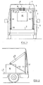
- Figure 1 shows a simplified view of a van 1 from its rear side with open doors.
- the car contains a level cargo bed 2, bounded by side walls 3 and a roof fell.
- the side walls 3 and the roof 4 are generally not sufficiently stable to attach a load.
- an outer bracket 5 is attached to the lateral boundaries of the loading area 2, for example, screwed tight, welded or fastened in a similar manner to the supporting structure of the motor vehicle.
- This outer bracket includes two substantially vertically arranged arms 6, which are connected to each other in the region of their upper ends by a horizontal cross member 7.
- the Material of this bracket 5 is a profile that has sufficient stability.
- an abutment 8 is arranged, which is a set of rollers for a pulley 9.
- each have a bearing 10 is mounted with a rotation axis at which the lower ends of the arms 11 of a second bracket 12 are rotatably mounted.
- the second bracket 12 is thus rotatable about the axis 10.
- the effective length of the bracket 12 from its axis 10 to its crossbar 13 is slightly smaller than the corresponding dimension of the outer bracket 5, so that the load bracket 12 can be pivoted under the counter bearing bracket 5 therethrough.
- a plurality of hooks 15 are mounted in the example shown, which form a suspension.
- a load 16 can be suspended on the two middle hooks 15.
- the hooks 15 may be attached over the entire length of the crossbar 13.
- a load 16 can be hung both left and right as well as in the middle. It is of course also conceivable that the hooks are slidably mounted in the crossbar 13.
- the load 16 can be set far out of the vehicle out. It is even possible, if the axle is located slightly above the loading surface, that the load can also be set down to a point that is slightly lower than the surface on which the vehicle is standing.
- the invention can also be applied when the motor vehicle is an unfastened vehicle.
- the outer bracket 8 having the bracket 5 may be secured, for example with struts.
Landscapes
- Engineering & Computer Science (AREA)
- Transportation (AREA)
- Mechanical Engineering (AREA)
- Body Structure For Vehicles (AREA)
- Forklifts And Lifting Vehicles (AREA)
- Valve-Gear Or Valve Arrangements (AREA)
- Valve Device For Special Equipments (AREA)
- Jib Cranes (AREA)
- Vehicle Cleaning, Maintenance, Repair, Refitting, And Outriggers (AREA)
Description
- Die Erfindung betrifft eine Einrichtung zum Einbringen von Lasten in mit einer Ladefläche versehene Kraftfahrzeuge, beispielsweise Kombis, Kleintransporter, Pickups oder Pritschenwagen.
- Bei solchen für kleinere Transporte verwendeten Kraftfahrzeugen werden häufig Lasten in den Transporter eingeladen und später wieder aus ihnen herausgenommen. Selbst wenn das Beladen an einer Stelle geschieht, wo fest installierte Beladeeinrichtungen vorhanden sind, so muss das Entladen häufig an Stellen geschehen, wo keine derartigen ortsfesten Einrichtungen zur Verfügung stehen. Dort besteht die Notwendigkeit, dass der Fahrer zum Teil auch unter Zeitdruck Gegenstände aus dem Kfz entnehmen muss, die häufig auch ein Gewicht haben, das sich nur schwer ohne Hilfe bewegen lässt. Umgekehrt kann es auch erforderlich sein, an solchen Stellen einzelne Gegenstände in das Kraftfahrzeug einzuladen. Selbst wenn die Gegenstände ein Gewicht haben, das der Fahrer nach tragen könnte, so kann auf Grund der Vielzahl von solchen Vorgängen die Arbeit einer Person nicht mehr zumutbar sein.
- Es ist bereits eine Hebevorrichtung für einen offenen Lastwagen bekannt (GB 800075), bei der ein U-förmiger Bügel im Bereich der Enden seiner beiden Schenkel gelagert ist. Zum Auf und Abbewegen des Bügels wird eine Hydraulikzylinder oder ein an dem Bügel im Bereich seiner Lagerung angreifendes Zahnradgetriebe verwendet.
- Der Erfindung liegt die Aufgabe zu Grunde, eine Möglichkeit zu schaffen, in solchen Fällen das leichte Be- und/oder Entladen von Kraftfahrzeugen, Kleintransportern oder dergleichen für die betreffende Person leichter zu gestalten.
- Zur Lösung dieser Aufgabe schlägt die Erfindung einen Lastenheber mit den im Anspruch 1 genannten Merkmalen vor. Weiterbildungen der Erfindung sind Gegenstand von Unteransprüchen.
- Der Lastenheber, wie er von der Erfindung vorgeschlagen wird, wird in einem Kfz montiert. Der Lastbügel ist um eine durch eine Welle, gebildete Drehachse so verschwenkbar gelagert, dass er von der einen auf die andere Seite der Drehachse über diese Drehachse hinüber verschwenkt werden kann. Die Verschwenkung geschieht gegenüber einem Gegenlager, das fest in dem Kfz angeordnet ist. Bei einem Kfz, das einen sehr stabilen Aufbau aufweist, kann das Gegenlager beispielsweise direkt an einer oberen Querstrebe angebracht sein. Zur Verschwenkung des Lastbügels gegenüber dem Gegenlager dient ein Getriebe. Dieses Getriebe kann von dem Bediener des Lastenhebers von Hand betätigt werden, oder es kann unter Umständen auch einen von der Batterie des Kraftfahrzeugs gespeisten elektrischen Antrieb aufweisen.
- In Weiterbildung der Erfindung ist vorgesehen, dass das Gegenlager im wesentlichen senkrecht oberhalb der Achse des Bügels und bei senkrecht stehenden Bügel oberhalb des Bügels angeordnet ist. Dadurch wird es möglich, ein Getriebe zu verwenden, das im wesentlichen auf Zug beansprucht wird.
- In nochmaliger Weiterbildung der Erfindung kann vorgesehen sein, dass es sich bei der Getriebeverbindung zwischen dem Lastbügel und dem Gegenlager um einen Flaschenzug handelt. Der Flaschenzug besteht aus sehr einfachen, leicht handzuhabenden und auch leicht zu wartenden Teilen. Die Rollen lassen sich sehr einfach mit geringer Reibung lagern, so dass das Getriebe sehr leichtgängig ist. Auch lässt sich die Untersetzung so einstellen, dass für die jeweiligen Gewichte gerade der richtige Aufwand einstellbar ist. Es gibt sehr einfach wirkende Sperren, die das Absenken der Last verhindern, wenn der Benutzer nicht mehr zieht oder das Seil des Flaschenzugs los lässt. Damit ist auch eine große Sicherheit des Lastenhebers gegeben.
- Um die Ladefläche gut ausnutzen zu können, kann erfindungsgemäß vorgesehen sein, dass die Drehachse unmittelbar oberhalb der Ladefläche des Kraftfahrzeugs angeordnet wird, damit auch der in der Höhe zur Verfügung stehende Raum durch den Lastbügel maximal ausgenutzt werden kann. Denn die Länge des Lastbügels von der Drehachse bis zur Aufhängeeinrichtung bestimmt den maximalen Verschwenkweg des Lastenhebers. Der Lastbügel selbst muss aber ja bei einem geschlossenen Kfz vollständig in dem Kfz angeordnet werden können.
- Da viele Kraftfahrzeuge keine für das Aufhängen von Lasten ausreichende Stabilität ihrer Dachkonstruktion haben, schlägt die Erfindung in Weiterbildung vor, in dem Kraftfahrzeug einen äußeren Bügel anzuordnen, an dem das Gegenlager befestigt ist. Dieser Bügel kann dann auch dazu dienen, in seinem unteren Bereich das die Drehachse des Lastbügels bildende Lager aufzunehmen. Der Lastbügel wird so dimensioniert, dass er mit geringem Abstand unter dem Gegenlagerbügel hindurch geschenkt werden kann.
- Erfindungsgemäß kann vorgesehen sein, dass die Achse des Lastbügels im Bereich des hinteren Endes der Ladefläche des Kraftfahrzeugs angeordnet ist. Falls es sich um einen Pickup oder ein sonstiges für härteren Einsatz bestimmtes Kraftfahrzeug handelt, kann unter Umständen die Drehachse auch hinter der Ladefläche auf einer Stoßstangenkonstruktion angebracht sein.
- Die Aufhängeeinrichtung, beispielsweise ein einfacher Haken, kann so an dem oberen Quersteg des Lastbügels angeordnet werden, dass die Last an beliebigen Stellen dieser Querstrebe angebracht werden kann.
- Weitere Merkmale, Einzelheiten und Vorzüge der Erfindung ergeben sich aus der folgenden Beschreibung einer bevorzugten Ausführungsform, den Patentansprüchen und der Zusammenfassung, deren beider Wortlaut durch Bezugnahme zum Inhalt der Beschreibung gemacht wird, sowie anhand der Zeichnung. Hierbei zeigen:
- Figur 1
- eine schematische Ansicht eines in einem Kastenwagen angeordneten Lastenhebers nach der Erfindung;
- Figur 2
- die Seitenansicht des Lastenhebers mit im Kfz abgesenkter Last;
- Figur 3
- die Seitenansicht in dem Zustand des Absetzens bzw.
Aufnehmens einer Last. - Figur 1 zeigt vereinfacht die Ansicht eines Kastenwagens 1 von seiner Rückseite her mit geöffneten Türen. Das Kfz enthält eine Ebene Ladefläche 2, begrenzt von Seitenwänden 3 und einem Dach fiel. Die Seitenwände 3 und das Dach 4 sind im Allgemeinen nicht ausreichend stabil, um eine Last anzuhängen.
- Auf der Ladefläche stehend ist an den seitlichen Begrenzungen der Ladefläche 2 ein äußerer Bügel 5 befestigt, beispielsweise festgeschraubt, festgeschweißt oder in ähnlicher Weise an der Tragkonstruktion des Kraftfahrzeugs befestigt. Dieser äußere Bügel enthält zwei im wesentlichen senkrecht angeordnete Arme 6, die im Bereich ihrer oberen Enden durch eine horizontale Querstrebe 7 miteinander verbunden sind. Das Material dieses Bügels 5 ist ein Profil, dass die ausreichende Stabilität aufweist.
- In der Mitte der oberen Querstrebe 7 ist ein Gegenlager 8 angeordnet, bei dem es sich um einen Satz von Rollen für einen Flaschenzug 9 handelt.
- Im Bereich der unteren Enden der äußeren Arme 6 des Bügels 5 ist jeweils ein Lager 10 mit einer Drehachse angebracht, an der die unteren Enden der Arme 11 eines zweiten Bügels 12 drehbar gelagert sind. Der zweite Bügel 12 ist also um die Achse 10 verdrehbar. Die wirksame Länge des Bügels 12 von seiner Achse 10 bis zu seiner Querstrebe 13 ist etwas kleiner als die entsprechende Abmessung des äußeren Bügels 5, so dass der Lastbügel 12 unter dem Gegenlagerbügel 5 hindurch verschwenkt werden kann.
- An der -oberen Querstrebe 13 des Lastbügels 12 sind im dargestellten Beispiel mehrere Haken 15 angebracht, die eine Aufhängeeinrichtung bilden. Schematisch ist dargestellt, dass an den beiden mittleren Haken 15 eine Last 16 aufgehängt werden kann. Die Haken 15 können über die gesamte Länge der Querstrebe 13 angebracht sein. Damit kann eine Last 16 sowohl links als auch rechts als auch in der Mitte aufgehängt werden. Es ist natürlich auch denkbar, dass die Haken verschiebbar in der Querstrebe 13 angebracht sind.
- Nun zu Figur 2. Aus der Position der Figur 1, in der der Lastbügel 12 senkrecht steht, ist er jetzt ins Innere des Kfz hinein verschwenkt, bis die Haken 15 unmittelbar oberhalb der Last 16 angeordnet sind. In dieser Position kann jetzt die Last 16 mit Hilfe der Aufhängeeinrichtung an der Querstrebe 13 des Lastbügels 12 befestigt werden. Anschließend wird, angedeutet durch den Pfeil 17, an dem Flaschenzug gezogen. Dies führt dazu, dass der Lastbügel 12 sich aufrichtet, bis er senkrecht steht. Dann liegen die Drehachse 10 des Lastbügels 12 und die Querstrebe 7 des Gegenlagerbügels 5 direkt übereinander in einer senkrecht verlaufenden Linie. Nun muss der Benutzer des Lastenhebers die Last und den Bügel 12 mit geringem Kraftaufwand gerade etwas über diesen Punkt auf die andere Seite hinüber ziehen, worauf dann die Last 16 abgesenkt werden kann. Dies kann durch langsames Nachlassen an dem Seil des Flaschenzugs geschehen. Die Last 16 senkt sich dann durch entsprechende Verschwenkung des Lastbügels 12 auf die andere Seite ab, bis die Position der Figur 3 erreicht ist. Hier kann die Last 16 von der Aufhängeeinrichtung gelöst werden.
- Die umgekehrte Vorgehensweise ist natürlich auch möglich.
- Da die die Drehachse bildende Welle 10 im Bereich des hinteren Endes der Ladefläche 2 angeordnet ist, kann die Last 16 weit aus dem Kfz heraus gesetzt werden. Es ist sogar möglich, wenn die Achse etwas oberhalb der Ladefläche angeordnet ist, dass die Last auch auf eine Stelle abgesetzt werden kann, die etwas tiefer liegt als die Fläche, auf der das Kfz steht.
- Die Erfindung kann auch dann Anwendung finden, wenn es sich bei dem Kfz um ein nicht geschlossenes Kfz handelt. Der äußere das Gegenlager 8 aufweisende Bügel 5 kann beispielsweise mit Streben gesichert sein.
Claims (8)
- Lastenheber für ein Kraftfahrzeug mit1.1 einem in dem Kraftfahrzeug anbringbaren Lastbügel (12), der1.1.1 im Bereich seines unteren Endes um eine horizontale Achse (10) auf beide Seiten der Achse (10) verschwenkbar ist und1.1.2 eine Aufhängeeinrichtung zum Aufhängen der Last (16) aufweist,1.2 einem in bzw. an dem Kraftfahrzeug anordenbaren Gegenlager (8), sowie mit1.3 einer Getriebeverbindung zwischen dem Lastbügel (12) und dem Gegenlager (8) mit einem Getriebe zur Verschwenkung des Lastbügels (12) gegenüber dem Gegenlager (8)
dadurch gekennzeichnet, dass1.4 das Gegenlager im wesentlichen senkrecht oberhalb der Achse (10) des Lastbügels (12) und bei senkrecht stehendem Lastbügel (12) oberhalb des Bügels angeordnet ist, so dass1.5 das Getriebe der Getriebeverbindung im wesentlichen auf Zug beansprucht wird. - Lastenheber nach Anspruch 1, bei dem die Getriebeverbindung einen Flaschenzug (9) aufweist.
- Lastenheber nach Anspruch 2, bei dem der Flaschenzug (9) eine Sperre aufweist.
- Lastenheber nach einem der vorhergehenden Ansprüche, bei dem die Drehachse (10) unmittelbar oberhalb einer Ladefläche (2) des Kraftfahrzeugs anordenbar ist.
- Lastenheber nach einem der vorhergehenden Ansprüche, bei dem das Gegenlager (8) an einen Bügel (5) angeordnet ist, der in bzw. an dem Kraftfahrzeug befestigbar ist.
- Lastenheber nach Anspruch 5, bei dem das die Achse bildende Lager (10) an dem Gegenlagerbügel (5) angeordnet ist.
- Lastenheber nach einem der vorhergehenden Ansprüche, bei dem die Achse (10) im Bereich des hinteren Endes der Ladefläche (2) des Kraftfahrzeugs anordenbar ist.
- Lastenheber nach einem der vorhergehenden Ansprüche, bei dem die Aufhängeeinrichtung an beliebigen Stellen des oberen Querstegs (7) des Lastbügels (12) angreifen kann.
Applications Claiming Priority (2)
| Application Number | Priority Date | Filing Date | Title |
|---|---|---|---|
| DE10310976 | 2003-03-07 | ||
| DE10310976A DE10310976A1 (de) | 2003-03-07 | 2003-03-07 | Lastenheber für ein Kraftfahrzeug |
Publications (2)
| Publication Number | Publication Date |
|---|---|
| EP1454871A1 EP1454871A1 (de) | 2004-09-08 |
| EP1454871B1 true EP1454871B1 (de) | 2007-05-16 |
Family
ID=32797907
Family Applications (1)
| Application Number | Title | Priority Date | Filing Date |
|---|---|---|---|
| EP04004774A Expired - Lifetime EP1454871B1 (de) | 2003-03-07 | 2004-03-02 | Lastenheber für ein KFZ |
Country Status (4)
| Country | Link |
|---|---|
| EP (1) | EP1454871B1 (de) |
| AT (1) | ATE362458T1 (de) |
| DE (2) | DE10310976A1 (de) |
| ES (1) | ES2286522T3 (de) |
Family Cites Families (11)
| Publication number | Priority date | Publication date | Assignee | Title |
|---|---|---|---|---|
| CH84974A (de) * | 1919-09-05 | 1920-05-01 | Schirmer Otto | Fahrbarer Kran. |
| GB311984A (en) * | 1928-07-21 | 1929-05-30 | Arthur Ernest Lake | Improvements in or relating to salvage cars and cranes therefor |
| DE621037C (de) * | 1934-06-23 | 1935-10-31 | Demag Akt Ges | Ladevorrichtung mit einer Plattform, welche durch den zu beladenden Wagen belastet wird |
| DE751773C (de) * | 1940-01-26 | 1952-10-13 | Bamag Meguin A G | Auf die Plattform eines Lastwagens aufsetzbarer Wippkran |
| US2596846A (en) * | 1949-08-18 | 1952-05-13 | Julius Z Feigelson | Portable crane |
| DE919012C (de) * | 1949-10-08 | 1954-10-11 | Wilhelm Ludowici Dr Ing | Kran mit einem die Last aufnehmenden Ausleger |
| GB800075A (en) * | 1955-11-22 | 1958-08-20 | Market Transp Ltd | Improvements in or relating to loading and unloading apparatus carried by vehicles |
| US3341038A (en) * | 1965-07-06 | 1967-09-12 | Harold T Wicklund | Truck hoist |
| US4216941A (en) * | 1978-05-22 | 1980-08-12 | Little Raymond L | Yoke hoist for use with pickup truck |
| GB2066771A (en) * | 1980-01-07 | 1981-07-15 | Mackenzie Crum M | Derrick |
| DE20205847U1 (de) * | 2002-04-15 | 2002-08-14 | G. Welsch Pgmbh S.P.R.L., Eupen | Lasthebevorrichtung zum Befördern von Lasten |
-
2003
- 2003-03-07 DE DE10310976A patent/DE10310976A1/de not_active Withdrawn
-
2004
- 2004-03-02 EP EP04004774A patent/EP1454871B1/de not_active Expired - Lifetime
- 2004-03-02 AT AT04004774T patent/ATE362458T1/de active
- 2004-03-02 DE DE502004003812T patent/DE502004003812D1/de not_active Expired - Lifetime
- 2004-03-02 ES ES04004774T patent/ES2286522T3/es not_active Expired - Lifetime
Also Published As
| Publication number | Publication date |
|---|---|
| DE10310976A1 (de) | 2004-09-16 |
| ATE362458T1 (de) | 2007-06-15 |
| EP1454871A1 (de) | 2004-09-08 |
| DE502004003812D1 (de) | 2007-06-28 |
| ES2286522T3 (es) | 2007-12-01 |
Similar Documents
| Publication | Publication Date | Title |
|---|---|---|
| EP2423147B1 (de) | Anordnung zum Wenden einer Last | |
| DE1756585A1 (de) | Ladegeschirr | |
| DE102010035895A1 (de) | Anordnung und Arbeitsverfahren zum Wenden einer hängenden Last | |
| DE1506293A1 (de) | Deck-Portalkran zum Laden von Schuten | |
| DE2902116A1 (de) | Vorrichtung zum austausch des regelstab-antriebs in einem kernreaktor | |
| DE1937845C3 (de) | Hublader | |
| DE499033C (de) | Hub- und Stapelwagen mit motorischem Fahrantrieb und einer gleichzeitig auf dem Wagenrahmen oder der Ladeplattform des Wagens drehbar angeordneten, zum Stapeln verwendbaren Hubvorrichtung | |
| DE1481201A1 (de) | Lasthandhabungsgeraet mit Scherenhubwerk | |
| EP1454871B1 (de) | Lastenheber für ein KFZ | |
| DE9418696U1 (de) | Vorrichtung zum Anheben und Entleeren von Recyclingbehältern | |
| DE1684756C3 (de) | Vorrichtung zum Abstellen von zwei Fahrzeugen übereinander | |
| DE1941940B2 (de) | Fahrzeug mit Hebevorrichtung für großvolumige Kästen, vorzugsweise aus Beton mit Ausnehmungen im Boden für teleskopisch längenveränderliche Beine der Hebevorrichtung | |
| DE102004037952A1 (de) | Kippvorrichtung für Schüttgut-Ladungsträger auf einem Schienen-Güterwagen mit Drehrahmen | |
| DE202011101434U1 (de) | Kompakt-Greiferlaufkatze | |
| DE69307324T2 (de) | Laufkatze | |
| DE4323983C1 (de) | Transportvorrichtung für Geldkassetten | |
| DE102019001683A1 (de) | Fahrzeug und Verfahren zu dessen Beladen mit einem Kraftfahrzeug | |
| DE102019001682B4 (de) | Fahrzeug, insbesondere Wohnmobil | |
| DE2312222A1 (de) | Anhaenger zum heben und abschleppen von fahrzeugen | |
| DE3113098C2 (de) | Hubbalken zum Transportieren eines kippbar aufgehängten Transportbehälters oder dergleichen | |
| DE4444330A1 (de) | Verfahren und Vorrichtung zum Absetzen und/oder Aufnehmen von Ladungsträgern | |
| DE3232899A1 (de) | Vorrichtung zur aufrechterhaltung gleichmaessiger hubhoehen an beiden seiten einer plattform | |
| EP0243343A2 (de) | Seilkran | |
| DE102015013643A1 (de) | Ladungsabstüzung für Innenlader-Fahrzeuge | |
| DE102019001681A1 (de) | Rampe |
Legal Events
| Date | Code | Title | Description |
|---|---|---|---|
| PUAI | Public reference made under article 153(3) epc to a published international application that has entered the european phase |
Free format text: ORIGINAL CODE: 0009012 |
|
| AK | Designated contracting states |
Kind code of ref document: A1 Designated state(s): AT BE BG CH CY CZ DE DK EE ES FI FR GB GR HU IE IT LI LU MC NL PL PT RO SE SI SK TR |
|
| AX | Request for extension of the european patent |
Extension state: AL LT LV MK |
|
| 17P | Request for examination filed |
Effective date: 20050122 |
|
| AKX | Designation fees paid |
Designated state(s): AT BE BG CH CY CZ DE DK EE ES FI FR GB GR HU IE IT LI LU MC NL PL PT RO SE SI SK TR |
|
| AXX | Extension fees paid |
Extension state: LT Payment date: 20050122 Extension state: LV Payment date: 20050122 |
|
| GRAP | Despatch of communication of intention to grant a patent |
Free format text: ORIGINAL CODE: EPIDOSNIGR1 |
|
| GRAS | Grant fee paid |
Free format text: ORIGINAL CODE: EPIDOSNIGR3 |
|
| GRAA | (expected) grant |
Free format text: ORIGINAL CODE: 0009210 |
|
| AK | Designated contracting states |
Kind code of ref document: B1 Designated state(s): AT BE BG CH CY CZ DE DK EE ES FI FR GB GR HU IE IT LI LU MC NL PL PT RO SE SI SK TR |
|
| AX | Request for extension of the european patent |
Extension state: LT LV |
|
| PG25 | Lapsed in a contracting state [announced via postgrant information from national office to epo] |
Ref country code: FI Free format text: LAPSE BECAUSE OF FAILURE TO SUBMIT A TRANSLATION OF THE DESCRIPTION OR TO PAY THE FEE WITHIN THE PRESCRIBED TIME-LIMIT Effective date: 20070516 |
|
| REG | Reference to a national code |
Ref country code: GB Ref legal event code: FG4D Free format text: NOT ENGLISH |
|
| REG | Reference to a national code |
Ref country code: CH Ref legal event code: EP |
|
| REG | Reference to a national code |
Ref country code: IE Ref legal event code: FG4D Free format text: LANGUAGE OF EP DOCUMENT: GERMAN |
|
| REF | Corresponds to: |
Ref document number: 502004003812 Country of ref document: DE Date of ref document: 20070628 Kind code of ref document: P |
|
| GBT | Gb: translation of ep patent filed (gb section 77(6)(a)/1977) |
Effective date: 20070717 |
|
| REG | Reference to a national code |
Ref country code: CH Ref legal event code: NV Representative=s name: ZIMMERLI, WAGNER & PARTNER AG |
|
| PG25 | Lapsed in a contracting state [announced via postgrant information from national office to epo] |
Ref country code: SE Free format text: LAPSE BECAUSE OF FAILURE TO SUBMIT A TRANSLATION OF THE DESCRIPTION OR TO PAY THE FEE WITHIN THE PRESCRIBED TIME-LIMIT Effective date: 20070816 |
|
| LTIE | Lt: invalidation of european patent or patent extension |
Effective date: 20070516 |
|
| NLV1 | Nl: lapsed or annulled due to failure to fulfill the requirements of art. 29p and 29m of the patents act | ||
| ET | Fr: translation filed | ||
| PG25 | Lapsed in a contracting state [announced via postgrant information from national office to epo] |
Ref country code: PL Free format text: LAPSE BECAUSE OF FAILURE TO SUBMIT A TRANSLATION OF THE DESCRIPTION OR TO PAY THE FEE WITHIN THE PRESCRIBED TIME-LIMIT Effective date: 20070516 |
|
| REG | Reference to a national code |
Ref country code: ES Ref legal event code: FG2A Ref document number: 2286522 Country of ref document: ES Kind code of ref document: T3 |
|
| REG | Reference to a national code |
Ref country code: IE Ref legal event code: FD4D |
|
| PG25 | Lapsed in a contracting state [announced via postgrant information from national office to epo] |
Ref country code: SI Free format text: LAPSE BECAUSE OF FAILURE TO SUBMIT A TRANSLATION OF THE DESCRIPTION OR TO PAY THE FEE WITHIN THE PRESCRIBED TIME-LIMIT Effective date: 20070516 Ref country code: DK Free format text: LAPSE BECAUSE OF FAILURE TO SUBMIT A TRANSLATION OF THE DESCRIPTION OR TO PAY THE FEE WITHIN THE PRESCRIBED TIME-LIMIT Effective date: 20070516 Ref country code: IE Free format text: LAPSE BECAUSE OF FAILURE TO SUBMIT A TRANSLATION OF THE DESCRIPTION OR TO PAY THE FEE WITHIN THE PRESCRIBED TIME-LIMIT Effective date: 20070516 Ref country code: CZ Free format text: LAPSE BECAUSE OF FAILURE TO SUBMIT A TRANSLATION OF THE DESCRIPTION OR TO PAY THE FEE WITHIN THE PRESCRIBED TIME-LIMIT Effective date: 20070516 Ref country code: NL Free format text: LAPSE BECAUSE OF FAILURE TO SUBMIT A TRANSLATION OF THE DESCRIPTION OR TO PAY THE FEE WITHIN THE PRESCRIBED TIME-LIMIT Effective date: 20070516 Ref country code: BG Free format text: LAPSE BECAUSE OF FAILURE TO SUBMIT A TRANSLATION OF THE DESCRIPTION OR TO PAY THE FEE WITHIN THE PRESCRIBED TIME-LIMIT Effective date: 20070816 Ref country code: PT Free format text: LAPSE BECAUSE OF FAILURE TO SUBMIT A TRANSLATION OF THE DESCRIPTION OR TO PAY THE FEE WITHIN THE PRESCRIBED TIME-LIMIT Effective date: 20071016 |
|
| PG25 | Lapsed in a contracting state [announced via postgrant information from national office to epo] |
Ref country code: SK Free format text: LAPSE BECAUSE OF FAILURE TO SUBMIT A TRANSLATION OF THE DESCRIPTION OR TO PAY THE FEE WITHIN THE PRESCRIBED TIME-LIMIT Effective date: 20070516 |
|
| PLBE | No opposition filed within time limit |
Free format text: ORIGINAL CODE: 0009261 |
|
| STAA | Information on the status of an ep patent application or granted ep patent |
Free format text: STATUS: NO OPPOSITION FILED WITHIN TIME LIMIT |
|
| 26N | No opposition filed |
Effective date: 20080219 |
|
| PG25 | Lapsed in a contracting state [announced via postgrant information from national office to epo] |
Ref country code: GR Free format text: LAPSE BECAUSE OF FAILURE TO SUBMIT A TRANSLATION OF THE DESCRIPTION OR TO PAY THE FEE WITHIN THE PRESCRIBED TIME-LIMIT Effective date: 20070817 |
|
| PG25 | Lapsed in a contracting state [announced via postgrant information from national office to epo] |
Ref country code: RO Free format text: LAPSE BECAUSE OF FAILURE TO SUBMIT A TRANSLATION OF THE DESCRIPTION OR TO PAY THE FEE WITHIN THE PRESCRIBED TIME-LIMIT Effective date: 20070516 |
|
| BERE | Be: lapsed |
Owner name: KNOLL, HERBERT Effective date: 20080331 |
|
| PG25 | Lapsed in a contracting state [announced via postgrant information from national office to epo] |
Ref country code: MC Free format text: LAPSE BECAUSE OF NON-PAYMENT OF DUE FEES Effective date: 20080331 |
|
| PG25 | Lapsed in a contracting state [announced via postgrant information from national office to epo] |
Ref country code: EE Free format text: LAPSE BECAUSE OF FAILURE TO SUBMIT A TRANSLATION OF THE DESCRIPTION OR TO PAY THE FEE WITHIN THE PRESCRIBED TIME-LIMIT Effective date: 20070516 |
|
| PG25 | Lapsed in a contracting state [announced via postgrant information from national office to epo] |
Ref country code: BE Free format text: LAPSE BECAUSE OF NON-PAYMENT OF DUE FEES Effective date: 20080331 |
|
| PG25 | Lapsed in a contracting state [announced via postgrant information from national office to epo] |
Ref country code: CY Free format text: LAPSE BECAUSE OF FAILURE TO SUBMIT A TRANSLATION OF THE DESCRIPTION OR TO PAY THE FEE WITHIN THE PRESCRIBED TIME-LIMIT Effective date: 20070516 |
|
| REG | Reference to a national code |
Ref country code: CH Ref legal event code: PFA Owner name: KNOELL, HERBERT Free format text: KNOELL, HERBERT#ALTER WEG 15#D-71546 ASPACH (DE) -TRANSFER TO- KNOELL, HERBERT#ALTER WEG 15#D-71546 ASPACH (DE) |
|
| PG25 | Lapsed in a contracting state [announced via postgrant information from national office to epo] |
Ref country code: LU Free format text: LAPSE BECAUSE OF NON-PAYMENT OF DUE FEES Effective date: 20080302 Ref country code: HU Free format text: LAPSE BECAUSE OF FAILURE TO SUBMIT A TRANSLATION OF THE DESCRIPTION OR TO PAY THE FEE WITHIN THE PRESCRIBED TIME-LIMIT Effective date: 20071117 |
|
| PG25 | Lapsed in a contracting state [announced via postgrant information from national office to epo] |
Ref country code: TR Free format text: LAPSE BECAUSE OF FAILURE TO SUBMIT A TRANSLATION OF THE DESCRIPTION OR TO PAY THE FEE WITHIN THE PRESCRIBED TIME-LIMIT Effective date: 20070516 |
|
| REG | Reference to a national code |
Ref country code: CH Ref legal event code: NV Representative=s name: WAGNER PATENT AG, CH |
|
| REG | Reference to a national code |
Ref country code: FR Ref legal event code: PLFP Year of fee payment: 12 |
|
| PGFP | Annual fee paid to national office [announced via postgrant information from national office to epo] |
Ref country code: DE Payment date: 20150330 Year of fee payment: 12 Ref country code: ES Payment date: 20150325 Year of fee payment: 12 Ref country code: CH Payment date: 20150325 Year of fee payment: 12 Ref country code: IT Payment date: 20150324 Year of fee payment: 12 |
|
| PGFP | Annual fee paid to national office [announced via postgrant information from national office to epo] |
Ref country code: AT Payment date: 20150320 Year of fee payment: 12 Ref country code: FR Payment date: 20150319 Year of fee payment: 12 Ref country code: GB Payment date: 20150324 Year of fee payment: 12 |
|
| REG | Reference to a national code |
Ref country code: DE Ref legal event code: R119 Ref document number: 502004003812 Country of ref document: DE |
|
| REG | Reference to a national code |
Ref country code: CH Ref legal event code: PL |
|
| REG | Reference to a national code |
Ref country code: AT Ref legal event code: MM01 Ref document number: 362458 Country of ref document: AT Kind code of ref document: T Effective date: 20160302 |
|
| GBPC | Gb: european patent ceased through non-payment of renewal fee |
Effective date: 20160302 |
|
| REG | Reference to a national code |
Ref country code: FR Ref legal event code: ST Effective date: 20161130 |
|
| PG25 | Lapsed in a contracting state [announced via postgrant information from national office to epo] |
Ref country code: LI Free format text: LAPSE BECAUSE OF NON-PAYMENT OF DUE FEES Effective date: 20160331 Ref country code: DE Free format text: LAPSE BECAUSE OF NON-PAYMENT OF DUE FEES Effective date: 20161001 Ref country code: GB Free format text: LAPSE BECAUSE OF NON-PAYMENT OF DUE FEES Effective date: 20160302 Ref country code: FR Free format text: LAPSE BECAUSE OF NON-PAYMENT OF DUE FEES Effective date: 20160331 Ref country code: CH Free format text: LAPSE BECAUSE OF NON-PAYMENT OF DUE FEES Effective date: 20160331 |
|
| PG25 | Lapsed in a contracting state [announced via postgrant information from national office to epo] |
Ref country code: AT Free format text: LAPSE BECAUSE OF NON-PAYMENT OF DUE FEES Effective date: 20160302 Ref country code: IT Free format text: LAPSE BECAUSE OF NON-PAYMENT OF DUE FEES Effective date: 20160302 |
|
| REG | Reference to a national code |
Ref country code: ES Ref legal event code: FD2A Effective date: 20170428 |
|
| PG25 | Lapsed in a contracting state [announced via postgrant information from national office to epo] |
Ref country code: ES Free format text: LAPSE BECAUSE OF NON-PAYMENT OF DUE FEES Effective date: 20160303 |