EP1455111A2 - Amortisseur hydraulique pour véhicule automobile - Google Patents
Amortisseur hydraulique pour véhicule automobile Download PDFInfo
- Publication number
- EP1455111A2 EP1455111A2 EP04002496A EP04002496A EP1455111A2 EP 1455111 A2 EP1455111 A2 EP 1455111A2 EP 04002496 A EP04002496 A EP 04002496A EP 04002496 A EP04002496 A EP 04002496A EP 1455111 A2 EP1455111 A2 EP 1455111A2
- Authority
- EP
- European Patent Office
- Prior art keywords
- bypass
- flat slide
- bypass channels
- slide valve
- vibration damper
- Prior art date
- Legal status (The legal status is an assumption and is not a legal conclusion. Google has not performed a legal analysis and makes no representation as to the accuracy of the status listed.)
- Granted
Links
Images
Classifications
-
- F—MECHANICAL ENGINEERING; LIGHTING; HEATING; WEAPONS; BLASTING
- F16—ENGINEERING ELEMENTS AND UNITS; GENERAL MEASURES FOR PRODUCING AND MAINTAINING EFFECTIVE FUNCTIONING OF MACHINES OR INSTALLATIONS; THERMAL INSULATION IN GENERAL
- F16F—SPRINGS; SHOCK-ABSORBERS; MEANS FOR DAMPING VIBRATION
- F16F9/00—Springs, vibration-dampers, shock-absorbers, or similarly-constructed movement-dampers using a fluid or the equivalent as damping medium
- F16F9/32—Details
- F16F9/44—Means on or in the damper for manual or non-automatic adjustment; such means combined with temperature correction
- F16F9/46—Means on or in the damper for manual or non-automatic adjustment; such means combined with temperature correction allowing control from a distance, i.e. location of means for control input being remote from site of valves, e.g. on damper external wall
- F16F9/466—Throttling control, i.e. regulation of flow passage geometry
Definitions
- the invention relates to a controllable vibration damper for motor vehicles according to the preamble of claim 1.
- vibration dampers are designed to be adjustable.
- the damping valves in the damper piston become additional controllable Bypass valves assigned.
- the regulation is usually done by electronic Control programs that are based on a wide range of measured values, such as vehicle speed, Steering wheel position and driving dynamics, the control the vibration damping.
- the bypass may be necessary for the bypass to have at least two bypass channels that are controlled depending on each other.
- bypass systems are from DE 40 20 045 C1 or DE 198 36 286 A1 known.
- a disadvantage of such provided with at least two bypass channels Bypassing results in the channels being opened or can be closed. This can be done gradually, as in DE 40 20 045 C1 or continuously, as in DE 198 36 286 A1.
- the invention is based, such generic hydraulic task Vibration damper to develop so that the at least two bypass channels depending on each other, but not necessarily opened one after the other and / or can be closed.
- the advantages achieved by the invention are in particular that the variation of the bypass cross-sections and the variation of the control cross-sections almost any bypass identifiers can be achieved, although the different bypass channels only via one control element, and thus only via a drive element assigned to the control element can be operated.
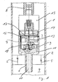
- the shock absorber has a cylinder 1, the interior of which is divided into two working spaces 3, 4 by a damping piston 2.
- the Damping piston 2 is shown in a known manner with only schematically Damping valves 5 and is provided via fasteners, not shown on a pin 6 of a bypass housing 7, which in turn with the Piston rod 8 is connected, attached.
- the bypass housing 7 carries a bypass piston 9, which is hydraulic in a first Bypass channel.
- This first bypass channel contains a central bore 10 through the pin 6, an adjoining pot space 11, in which the Bypass piston 9 lies and continues in a drain channel 12, which in turn via an opening 13 through the bypass housing 7 in the upper work space 3 ends.
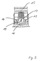
- a flat slide valve 14 Transversely to the extent of the drain channel 12 is a flat slide valve 14, which over a control magnet 15, not shown, can be moved axially.
- the flat slide valve 14 has a control breakthrough 16 formed by which the drain channel 12 more or less closed can be.
- Another bypass channel runs hydraulically parallel to the first bypass channel.
- This further bypass channel consists of one above the drain channel 12 arranged, extending in the same direction bore 17.
- the other Bypass channel is then through a bore 17 adjoining this bore 18 added, which runs out in the lower region of the pot space 11, where it has a direct connection to the bore 10.
- the second bypass is therefore not influenced by the bypass piston 9.
- the flat slide is in the area of the horizontal bore 17 of the second bypass channel 14 formed with an elongated control opening 19.
- the control breakthroughs 16, 19 have the same effect, i.e. while dressing of the control magnet 15, whereby the flat slide 14 moved upwards both control openings 16, 19 open.
- other control systems are in conceivable in the same way.
- the control magnet 15 is de-energized, such as he is shown in the embodiment in FIGS. 1 and 2
- the tax breakthrough 19 are at the level of the bore 17, so that the second bypass channel is open and the Drain channel 12 can be closed by the flat slide 14, like this one corresponds to the embodiment.
- the control magnet 15 when tightening the control magnet 15 the bore 17 are closed and the tax breakthrough 16 would corresponding to the lifting of the flat slide 14, slowly the drain channel 12 release.
- bypass cross section could then be quick here opened and then narrowed again while the other bypass cross section could be opened slowly so that both bypass cross sections in the middle position of the flat slide 14 would have opened a largest cross section.
Landscapes
- Engineering & Computer Science (AREA)
- General Engineering & Computer Science (AREA)
- Mechanical Engineering (AREA)
- Fluid-Damping Devices (AREA)
- Vibration Prevention Devices (AREA)
- Fluid-Pressure Circuits (AREA)
Applications Claiming Priority (2)
| Application Number | Priority Date | Filing Date | Title |
|---|---|---|---|
| DE10309743A DE10309743B3 (de) | 2003-03-06 | 2003-03-06 | Hydraulischer Schwingungsdämpfer für Kraftfahrzeuge |
| DE10309743 | 2003-03-06 |
Publications (3)
| Publication Number | Publication Date |
|---|---|
| EP1455111A2 true EP1455111A2 (fr) | 2004-09-08 |
| EP1455111A3 EP1455111A3 (fr) | 2004-12-15 |
| EP1455111B1 EP1455111B1 (fr) | 2005-12-07 |
Family
ID=32185993
Family Applications (1)
| Application Number | Title | Priority Date | Filing Date |
|---|---|---|---|
| EP04002496A Expired - Lifetime EP1455111B1 (fr) | 2003-03-06 | 2004-02-05 | Amortisseur hydraulique pour véhicule automobile |
Country Status (4)
| Country | Link |
|---|---|
| US (1) | US7066307B2 (fr) |
| EP (1) | EP1455111B1 (fr) |
| DE (2) | DE10309743B3 (fr) |
| ES (1) | ES2255000T3 (fr) |
Families Citing this family (3)
| Publication number | Priority date | Publication date | Assignee | Title |
|---|---|---|---|---|
| DE102005015628B4 (de) * | 2005-04-06 | 2015-10-29 | Dr. Ing. H.C. F. Porsche Aktiengesellschaft | Ventil |
| DE102012016711A1 (de) * | 2012-08-22 | 2014-02-27 | Volkswagen Aktiengesellschaft | Ventilkolbenanordnung für einen Schalt-Schwingungsdämpfer |
| DE102016220722B4 (de) * | 2016-10-21 | 2023-05-25 | Volkswagen Aktiengesellschaft | Ventil-Kolben-Anordnung für einen Schwingungsdämpfer |
Citations (3)
| Publication number | Priority date | Publication date | Assignee | Title |
|---|---|---|---|---|
| DE4020045C1 (en) | 1990-06-23 | 1991-08-29 | August Bilstein Gmbh & Co. Kg, 5828 Ennepetal, De | Hydraulic shock absorber for vehicle - has coil compression springs mounted between core housing and armature |
| DE19836286A1 (de) | 1998-08-11 | 2000-02-24 | Krupp Bilstein Gmbh | Hydraulischer Schwingungsdämpfer für Kraftfahrzeuge |
| DE10040518C1 (de) | 2000-08-18 | 2002-02-21 | Krupp Bilstein Gmbh | Regelbarer Schwingungsdämpfer für Kraftfahrzeuge |
Family Cites Families (8)
| Publication number | Priority date | Publication date | Assignee | Title |
|---|---|---|---|---|
| DE3518327A1 (de) * | 1985-05-22 | 1986-11-27 | Boge Gmbh, 5208 Eitorf | Hydraulischer, verstellbarer schwingungsdaempfer |
| DE3832625C2 (de) * | 1987-10-13 | 1999-06-24 | Hauni Werke Koerber & Co Kg | Schwingungsdämpfer mit veränderbarer Dämpfungscharakteristik |
| GB2220726B (en) * | 1988-06-07 | 1992-07-08 | Tokico Ltd | A hydraulic damper of adjustable damping force type |
| JP2639396B2 (ja) * | 1988-07-11 | 1997-08-13 | ダイムラー―ベンツ・アクチエンゲゼルシヤフト | 液圧入れ子式緩衝器 |
| JP2964148B2 (ja) * | 1989-04-20 | 1999-10-18 | トキコ株式会社 | 減衰力調整式油圧緩衝器 |
| DE3942477A1 (de) * | 1989-12-22 | 1991-07-04 | Bilstein August Gmbh Co Kg | Bypass-ventil mit abstimmbaren kennungen fuer regelbare und steuerbare schwingungsdaempfer |
| JP2001349366A (ja) * | 2001-04-09 | 2001-12-21 | Tokico Ltd | 減衰力調整式油圧緩衝器 |
| DE10206104C1 (de) * | 2002-02-13 | 2003-05-28 | Thyssen Krupp Bilstein Gmbh | Dämpferkolben für hydraulische Einrichtungen |
-
2003
- 2003-03-06 DE DE10309743A patent/DE10309743B3/de not_active Expired - Fee Related
-
2004
- 2004-02-05 ES ES04002496T patent/ES2255000T3/es not_active Expired - Lifetime
- 2004-02-05 EP EP04002496A patent/EP1455111B1/fr not_active Expired - Lifetime
- 2004-02-05 DE DE502004000157T patent/DE502004000157D1/de not_active Expired - Lifetime
- 2004-02-06 US US10/773,852 patent/US7066307B2/en not_active Expired - Fee Related
Patent Citations (3)
| Publication number | Priority date | Publication date | Assignee | Title |
|---|---|---|---|---|
| DE4020045C1 (en) | 1990-06-23 | 1991-08-29 | August Bilstein Gmbh & Co. Kg, 5828 Ennepetal, De | Hydraulic shock absorber for vehicle - has coil compression springs mounted between core housing and armature |
| DE19836286A1 (de) | 1998-08-11 | 2000-02-24 | Krupp Bilstein Gmbh | Hydraulischer Schwingungsdämpfer für Kraftfahrzeuge |
| DE10040518C1 (de) | 2000-08-18 | 2002-02-21 | Krupp Bilstein Gmbh | Regelbarer Schwingungsdämpfer für Kraftfahrzeuge |
Also Published As
| Publication number | Publication date |
|---|---|
| ES2255000T3 (es) | 2006-06-16 |
| US20040173423A1 (en) | 2004-09-09 |
| DE502004000157D1 (de) | 2006-01-12 |
| EP1455111B1 (fr) | 2005-12-07 |
| DE10309743B3 (de) | 2004-05-27 |
| US7066307B2 (en) | 2006-06-27 |
| EP1455111A3 (fr) | 2004-12-15 |
Similar Documents
| Publication | Publication Date | Title |
|---|---|---|
| DE60114584T2 (de) | Schwingungsdämpfungssystem mit einem hydraulischen dämpfer, welcher über eine feldempfindliche flüssigkeit gesteuert wird | |
| DE3827255C2 (de) | Regelbarer hydraulischer Schwingungsdämpfer für Kraftfahrzeuge | |
| EP0405123B1 (fr) | Soupape électromagnétique à deux sens pour réglage d'une dérivation | |
| DE4219141C2 (de) | Hydraulischer Dämpfer | |
| DE3532633C2 (de) | Hydraulischer Dämpfer | |
| EP2255103B1 (fr) | Amortisseur de vibrations comportant une soupape attachée au tube d'amortisseur | |
| DE4040523A1 (de) | Kraftausgeglichener, hydraulischer kolbenschieber | |
| DE3532292A1 (de) | Schwingungsdaempfer mit verstellbarer daempfkraft | |
| DE2121775C3 (fr) | ||
| EP0435357A1 (fr) | Soupape de dérivation à caractéristiques variables pour amortisseurs de vibrations réglables | |
| DE8529250U1 (de) | Pneumatischer oder hydraulischer Stoßdämpfer | |
| DE19642837C1 (de) | Dämpferventil | |
| DE4109180C2 (fr) | ||
| EP4248105A1 (fr) | Amortisseur hydraulique | |
| DE19849221B4 (de) | Schwingungsdämpfer mit veränderbarer Dämpfkraft | |
| DE69007406T2 (de) | Kolben für Druckzylinder. | |
| DE2800630A1 (de) | Schwingungsdaempfer mit geschwindigkeitsabhaengiger veraenderung der daempfwirkung | |
| DE10319390B4 (de) | Hydraulischer Stoßdämpfer | |
| DE19956769A1 (de) | Längenvariable Zahnstangenlenkung | |
| DE10309743B3 (de) | Hydraulischer Schwingungsdämpfer für Kraftfahrzeuge | |
| DE2757711A1 (de) | Hydraulischer teleskopstossdaempfer fuer ein kraftfahrzeug | |
| EP1182374B1 (fr) | Amortisseur réglable pour véhicules automobiles, et méthode de réglage d'un amortisseur | |
| EP1281888B1 (fr) | Amortisseur hydraulique | |
| EP0500534B1 (fr) | Amortisseur de vibrations reglable | |
| DE4427273B4 (de) | Hydraulischer Teleskop-Schwingungsdämpfer |
Legal Events
| Date | Code | Title | Description |
|---|---|---|---|
| PUAI | Public reference made under article 153(3) epc to a published international application that has entered the european phase |
Free format text: ORIGINAL CODE: 0009012 |
|
| AK | Designated contracting states |
Kind code of ref document: A2 Designated state(s): AT BE BG CH CY CZ DE DK EE ES FI FR GB GR HU IE IT LI LU MC NL PT RO SE SI SK TR |
|
| AX | Request for extension of the european patent |
Extension state: AL LT LV MK |
|
| PUAL | Search report despatched |
Free format text: ORIGINAL CODE: 0009013 |
|
| AK | Designated contracting states |
Kind code of ref document: A3 Designated state(s): AT BE BG CH CY CZ DE DK EE ES FI FR GB GR HU IE IT LI LU MC NL PT RO SE SI SK TR |
|
| AX | Request for extension of the european patent |
Extension state: AL LT LV MK |
|
| 17P | Request for examination filed |
Effective date: 20050111 |
|
| 17Q | First examination report despatched |
Effective date: 20050221 |
|
| GRAP | Despatch of communication of intention to grant a patent |
Free format text: ORIGINAL CODE: EPIDOSNIGR1 |
|
| GRAS | Grant fee paid |
Free format text: ORIGINAL CODE: EPIDOSNIGR3 |
|
| AKX | Designation fees paid |
Designated state(s): DE ES FR GB IT |
|
| GRAA | (expected) grant |
Free format text: ORIGINAL CODE: 0009210 |
|
| AK | Designated contracting states |
Kind code of ref document: B1 Designated state(s): DE ES FR GB IT |
|
| REG | Reference to a national code |
Ref country code: GB Ref legal event code: FG4D Free format text: NOT ENGLISH |
|
| GBT | Gb: translation of ep patent filed (gb section 77(6)(a)/1977) |
Effective date: 20051207 |
|
| REF | Corresponds to: |
Ref document number: 502004000157 Country of ref document: DE Date of ref document: 20060112 Kind code of ref document: P |
|
| ET | Fr: translation filed | ||
| REG | Reference to a national code |
Ref country code: ES Ref legal event code: FG2A Ref document number: 2255000 Country of ref document: ES Kind code of ref document: T3 |
|
| PLBE | No opposition filed within time limit |
Free format text: ORIGINAL CODE: 0009261 |
|
| STAA | Information on the status of an ep patent application or granted ep patent |
Free format text: STATUS: NO OPPOSITION FILED WITHIN TIME LIMIT |
|
| 26N | No opposition filed |
Effective date: 20060908 |
|
| PGFP | Annual fee paid to national office [announced via postgrant information from national office to epo] |
Ref country code: IT Payment date: 20120221 Year of fee payment: 9 |
|
| PGFP | Annual fee paid to national office [announced via postgrant information from national office to epo] |
Ref country code: FR Payment date: 20130301 Year of fee payment: 10 Ref country code: ES Payment date: 20130227 Year of fee payment: 10 Ref country code: DE Payment date: 20130219 Year of fee payment: 10 Ref country code: GB Payment date: 20130218 Year of fee payment: 10 |
|
| REG | Reference to a national code |
Ref country code: DE Ref legal event code: R119 Ref document number: 502004000157 Country of ref document: DE |
|
| GBPC | Gb: european patent ceased through non-payment of renewal fee |
Effective date: 20140205 |
|
| REG | Reference to a national code |
Ref country code: FR Ref legal event code: ST Effective date: 20141031 |
|
| REG | Reference to a national code |
Ref country code: DE Ref legal event code: R119 Ref document number: 502004000157 Country of ref document: DE Effective date: 20140902 |
|
| PG25 | Lapsed in a contracting state [announced via postgrant information from national office to epo] |
Ref country code: DE Free format text: LAPSE BECAUSE OF NON-PAYMENT OF DUE FEES Effective date: 20140902 Ref country code: FR Free format text: LAPSE BECAUSE OF NON-PAYMENT OF DUE FEES Effective date: 20140228 Ref country code: GB Free format text: LAPSE BECAUSE OF NON-PAYMENT OF DUE FEES Effective date: 20140205 |
|
| PG25 | Lapsed in a contracting state [announced via postgrant information from national office to epo] |
Ref country code: IT Free format text: LAPSE BECAUSE OF NON-PAYMENT OF DUE FEES Effective date: 20140205 |
|
| PG25 | Lapsed in a contracting state [announced via postgrant information from national office to epo] |
Ref country code: ES Free format text: LAPSE BECAUSE OF NON-PAYMENT OF DUE FEES Effective date: 20140206 |