EP1455183B1 - Procede et appareil permettant de reduire une largeur de pic associe a l'etablissement d'un champ electrique - Google Patents
Procede et appareil permettant de reduire une largeur de pic associe a l'etablissement d'un champ electrique Download PDFInfo
- Publication number
- EP1455183B1 EP1455183B1 EP04013127.8A EP04013127A EP1455183B1 EP 1455183 B1 EP1455183 B1 EP 1455183B1 EP 04013127 A EP04013127 A EP 04013127A EP 1455183 B1 EP1455183 B1 EP 1455183B1
- Authority
- EP
- European Patent Office
- Prior art keywords
- electric field
- ramp
- separation medium
- initial electric
- temperature
- Prior art date
- Legal status (The legal status is an assumption and is not a legal conclusion. Google has not performed a legal analysis and makes no representation as to the accuracy of the status listed.)
- Expired - Lifetime
Links
- 230000005684 electric field Effects 0.000 title claims abstract description 129
- 238000000034 method Methods 0.000 title claims abstract description 38
- 238000000926 separation method Methods 0.000 claims abstract description 116
- 238000005251 capillar electrophoresis Methods 0.000 claims abstract description 32
- 239000012530 fluid Substances 0.000 claims description 22
- 239000002773 nucleotide Substances 0.000 claims description 22
- 125000003729 nucleotide group Chemical group 0.000 claims description 16
- 238000001962 electrophoresis Methods 0.000 claims description 12
- 230000000977 initiatory effect Effects 0.000 claims description 12
- 239000012491 analyte Substances 0.000 claims description 9
- 238000006073 displacement reaction Methods 0.000 claims description 9
- 230000005012 migration Effects 0.000 claims description 8
- 238000013508 migration Methods 0.000 claims description 8
- 108020004707 nucleic acids Proteins 0.000 claims description 3
- 102000039446 nucleic acids Human genes 0.000 claims description 3
- 150000007523 nucleic acids Chemical class 0.000 claims description 3
- 230000009969 flowable effect Effects 0.000 claims 1
- 230000008569 process Effects 0.000 abstract description 5
- XSQUKJJJFZCRTK-UHFFFAOYSA-N Urea Chemical compound NC(N)=O XSQUKJJJFZCRTK-UHFFFAOYSA-N 0.000 description 22
- 239000004202 carbamide Substances 0.000 description 22
- 230000000694 effects Effects 0.000 description 18
- 239000000463 material Substances 0.000 description 17
- 239000012634 fragment Substances 0.000 description 12
- 230000009467 reduction Effects 0.000 description 9
- 108020004414 DNA Proteins 0.000 description 7
- 239000000203 mixture Substances 0.000 description 7
- 229920000642 polymer Polymers 0.000 description 6
- 239000003398 denaturant Substances 0.000 description 5
- ZHNUHDYFZUAESO-UHFFFAOYSA-N Formamide Chemical compound NC=O ZHNUHDYFZUAESO-UHFFFAOYSA-N 0.000 description 4
- VYPSYNLAJGMNEJ-UHFFFAOYSA-N Silicium dioxide Chemical compound O=[Si]=O VYPSYNLAJGMNEJ-UHFFFAOYSA-N 0.000 description 4
- 238000004458 analytical method Methods 0.000 description 4
- 230000008859 change Effects 0.000 description 4
- 230000007423 decrease Effects 0.000 description 4
- 230000003247 decreasing effect Effects 0.000 description 4
- 238000001514 detection method Methods 0.000 description 4
- 239000005350 fused silica glass Substances 0.000 description 4
- 238000010438 heat treatment Methods 0.000 description 4
- 230000004044 response Effects 0.000 description 4
- 239000000243 solution Substances 0.000 description 4
- 238000012546 transfer Methods 0.000 description 4
- 238000001712 DNA sequencing Methods 0.000 description 3
- 239000004698 Polyethylene Substances 0.000 description 3
- 238000002347 injection Methods 0.000 description 3
- 239000007924 injection Substances 0.000 description 3
- 238000012986 modification Methods 0.000 description 3
- 230000004048 modification Effects 0.000 description 3
- 101100244535 Saccharomyces cerevisiae (strain ATCC 204508 / S288c) POP6 gene Proteins 0.000 description 2
- 101100244540 Schizosaccharomyces pombe (strain 972 / ATCC 24843) pop7 gene Proteins 0.000 description 2
- 230000006872 improvement Effects 0.000 description 2
- 238000012886 linear function Methods 0.000 description 2
- 239000006193 liquid solution Substances 0.000 description 2
- 230000007246 mechanism Effects 0.000 description 2
- 238000010008 shearing Methods 0.000 description 2
- XLYOFNOQVPJJNP-UHFFFAOYSA-N water Substances O XLYOFNOQVPJJNP-UHFFFAOYSA-N 0.000 description 2
- 102000053602 DNA Human genes 0.000 description 1
- 239000003109 Disodium ethylene diamine tetraacetate Substances 0.000 description 1
- ZGTMUACCHSMWAC-UHFFFAOYSA-L EDTA disodium salt (anhydrous) Chemical compound [Na+].[Na+].OC(=O)CN(CC([O-])=O)CCN(CC(O)=O)CC([O-])=O ZGTMUACCHSMWAC-UHFFFAOYSA-L 0.000 description 1
- -1 Polyethylene Polymers 0.000 description 1
- 239000004642 Polyimide Substances 0.000 description 1
- 108020004682 Single-Stranded DNA Proteins 0.000 description 1
- 229920001222 biopolymer Polymers 0.000 description 1
- 230000015572 biosynthetic process Effects 0.000 description 1
- 239000005388 borosilicate glass Substances 0.000 description 1
- 239000007853 buffer solution Substances 0.000 description 1
- 239000000470 constituent Substances 0.000 description 1
- 229920006037 cross link polymer Polymers 0.000 description 1
- 239000003599 detergent Substances 0.000 description 1
- 238000009792 diffusion process Methods 0.000 description 1
- 235000019301 disodium ethylene diamine tetraacetate Nutrition 0.000 description 1
- 238000005516 engineering process Methods 0.000 description 1
- 238000005530 etching Methods 0.000 description 1
- 238000002474 experimental method Methods 0.000 description 1
- 238000001917 fluorescence detection Methods 0.000 description 1
- 238000009472 formulation Methods 0.000 description 1
- 239000000499 gel Substances 0.000 description 1
- 230000002068 genetic effect Effects 0.000 description 1
- 230000003993 interaction Effects 0.000 description 1
- 238000004519 manufacturing process Methods 0.000 description 1
- 238000013507 mapping Methods 0.000 description 1
- 238000005259 measurement Methods 0.000 description 1
- 238000012544 monitoring process Methods 0.000 description 1
- 230000003287 optical effect Effects 0.000 description 1
- 235000020030 perry Nutrition 0.000 description 1
- 238000000206 photolithography Methods 0.000 description 1
- 229920000573 polyethylene Polymers 0.000 description 1
- 229920001721 polyimide Polymers 0.000 description 1
- 108091033319 polynucleotide Proteins 0.000 description 1
- 102000040430 polynucleotide Human genes 0.000 description 1
- 239000002157 polynucleotide Substances 0.000 description 1
- 239000004800 polyvinyl chloride Substances 0.000 description 1
- 229920000915 polyvinyl chloride Polymers 0.000 description 1
- 108090000623 proteins and genes Proteins 0.000 description 1
- 102000004169 proteins and genes Human genes 0.000 description 1
- 150000003384 small molecules Chemical class 0.000 description 1
- 239000002904 solvent Substances 0.000 description 1
- 239000000126 substance Substances 0.000 description 1
- 239000000758 substrate Substances 0.000 description 1
Images


Classifications
-
- G—PHYSICS
- G01—MEASURING; TESTING
- G01N—INVESTIGATING OR ANALYSING MATERIALS BY DETERMINING THEIR CHEMICAL OR PHYSICAL PROPERTIES
- G01N27/00—Investigating or analysing materials by the use of electric, electrochemical, or magnetic means
- G01N27/26—Investigating or analysing materials by the use of electric, electrochemical, or magnetic means by investigating electrochemical variables; by using electrolysis or electrophoresis
- G01N27/416—Systems
- G01N27/447—Systems using electrophoresis
- G01N27/44704—Details; Accessories
- G01N27/44708—Cooling
Definitions
- This invention relates to methods and apparatus for performing capillary electrophoresis. More specifically, this invention is directed towards methods and apparatus useful for reducing peak broadening caused during the establishment of a run field used to conduct the capillary electrophoresis process.
- a particularly preferred electrophoresis format is capillary electrophoresis (CE), where the electrophoresis is performed in a capillary channel having a small internal diameter, e.g., between 5 and 100 ⁇ m.
- capillary electrophoresis results in enhanced separation performance over traditional slab-based formats because the superior ability of the narrow-bore capillary to dissipate Joule heat allows for the use of high electrical fields thereby resulting in fast separations in which of analyte diffusion is reduced.
- capillary electrophoresis is well adapted to automation because of the ability to automate the steps of sample loading, analyte detection, and replenishment of the separation medium.
- the present invention is directed towards the discovery of methods and apparatus useful for increasing the separation performance of capillary electrophoresis separations performed in a fluid separation medium by controlling the rate of increase of the electric field strength and the temperature of the separation medium during an initial-electric-field-ramp stage of the capillary electrophoresis process.
- a capillary electrophoresis method wherein a run field is established during an initial electric field ramp in a controlled manner according to a pre-defined ramp rate.
- the run field is established at a ramp rate no greater than about 5 V/cm-s.
- the run field is established over a period of at least about ten seconds.
- the run field is established at a ramp rate which results in a reduction in the amount of peak broadening associated with the establishment of the run field by at least about 10%.
- the run field is established at a ramp rate which results in an increase in a length of read of at least about 20 nucleotides over that achieved when the run field is not established in a controlled manner.
- a method for producing a desired reduction in an amount of peak broadening caused during establishment of a run field comprising, for each of a plurality of electrophoretic runs, establishing the run field at each of a plurality of different ramp rates, at least some of which ramp rates are not greater than about 5 V/cm-s; analyzing a degree of peak broadening observed for each run; and selecting a ramp rate which is no greater than that which produced a desired reduction in peak broadening.
- a capillary electrophoresis method in which analyte species are separated by differential electrophoretic migration through a fluid separation medium located within a capillary under the influence of a run field, an improvement for reducing the peak broadening associated with the establishment of the run field comprising reducing a temperature of an environment surrounding the capillary during an initial electric field ramp.
- the temperature of the environment surrounding the capillary is reduced by an amount sufficient to maintain an average temperature of the separation medium during such initial electric field ramp to within about 0.4 °C of the average temperature of the separation medium prior to initiating the initial electric field ramp.
- the temperature of the environment surrounding the capillary is reduced by an amount sufficient to maintain an average temperature of the separation medium during such initial electric field ramp substantially constant with respect to an average temperature of the separation medium prior to initiating the initial electric field ramp to an extent sufficient to result in a displacement of the fluid separation medium at an inlet end of the capillary during the initial electric field ramp of less than about 600 ⁇ m.
- the temperature of the environment surrounding the capillary is reduced by an amount sufficient to maintain an average temperature of the separation medium during such initial electric field ramp substantially constant with respect to an average temperature of the separation medium prior to initiating the initial electric field ramp to an extent sufficient to increase a length of read by at least about 20 nucleotides.
- the invention is based in part on the discovery that a substantial amount of peak broadening is caused when a run field is first established, and that such peak broadening can be greatly reduced by establishing the run field in a controlled manner during an initial electric field ramp, and/or by maintaining the temperature of the separation medium at a constant value during the establishment of the run field.
- Separatation medium means a medium typically located within the lumen of a capillary through which an electrophoretic separation is conducted.
- exemplary separation media include crosslinked gels, un-crosslinked polymer solutions, or polymer-free solvents, e.g., buffered water.
- separation media may include denaturants such as detergents, e.g., SDS, or organics, e.g., urea or formamide.
- Fluid separation medium means an electrophoretic separation medium that cannot sustain a shearing stress in the absence of motion, i.e., a medium that flows in response to a shearing stress.
- fluid separation medium include but are not limited to liquids and liquid solutions, e.g., buffered aqueous polymer solutions.
- Random field means an electric field used to conduct an electrophoresis separation. Typical run fields used in capillary electrophoresis range from about 50 V/cm to about 3000 V/cm or greater.
- Initial electric field ramp means an electric field versus time profile during a period in which a run field is initially established.
- Random rate means a run field, E, divided by a total elapsed time of an initial electric field ramp, T. For example, if a run field is 100 V/cm and an initial field ramp takes ten seconds to reach the run field, than the ramp rate is 10 V/cm-s.
- Capillary or “capillary tube” meanstubes or channels or other structure capable of supporting a volume of separation medium.
- the geometry of a capillary may vary widely and includes tubes with circular, rectangular or square cross-sections, channels, groved plates, and the like.
- Capillaries may be fabricated by a wide range of well known technologies, e.g., pulling, etching, photolithography, and the like.
- An important feature of a capillary for use with the invention is the surface-area-to-volume ratio of the capillary lumen. High values of this ratio permit efficient dissipation of Joule heat produced during electrophoresis. Preferably, ratios in the range of about 0.4 to .04 ⁇ m -1 are employed.
- Capillaries may be formed as individual elements, or as channels formed in a monolithic substrate (e.g., Pace, U.S. Patent No. 4,908,112 ; Soane and Soane, U.S. Patent No. 5,126,022 ).
- Capillaries include an "inlet end" through which sample analytes are introduced into the lumen of the capillary.
- Joule heating e.g., Capillary Electrophoresis Theory and Practice, Chap. 1, Grossman and Colburn, eds., Academic Press, (1992 )
- Joule heating will result in both an increase in the average temperature of the separation medium, ⁇ T, and the formation of a parabolic radial temperature profile within the separation medium such that the temperature of the separation medium is higher at the centerline of the lumen and lower at the periphery.
- the magnitude of the temperature rise ⁇ T is a function of a number of parameters including but not limited to the shape, materials and dimensions of the capillary, the thermal conductivity of the separation medium and capillary materials, the efficiency of heat transfer between the capillary and the surrounding environment, the electrical conductivity of the separation medium, and the magnitude of the temperature dependence of the electrical conductivity of the separation medium.
- the magnitude of ⁇ T is generally a non-linear function of these parameters.
- thermal expansion coefficient means a proportionality constant relating an increase in a dimension of a material, e.g., length, area or volume, to an original dimension of the material, as the result of an increase in the temperature of the material.
- the displacement will (1) increase with increasing capillary length, (2) will increase with increasing thermal expansion coefficient of the fluid separation medium, (3) will increase with increasing electrical conductivity of the fluid separation medium, (4) will increase with decreasing heat transfer coefficient between the exterior surface of the capillary and the surroundings, (5) will increase with increasing run field, (6) and will increase with increasing capillary internal diameter.
- the present invention comprises methods and apparatus for reducing the amount of peak broadening caused by the uncontrolled establishment of a run field in a CE separation employing a fluid separation medium. More specifically, this aspect of the invention comprises a capillary electrophoresis system in which analyte species, e.g., nucleic acids, are separated by differential electrophoretic migration through a fluid separation medium under the influence of a run field E, wherein the run field is established during an initial electric field ramp in a controlled manner according to a defined electric-field vs. time profile having a characteristic ramp rate.
- analyte species e.g., nucleic acids
- Exemplary preferred electric field vs. time profiles include but are not limited to discontinuous multi-step profiles, continuous linear profiles, continuous non-linear profiles, or combinations of such discontinuous and continuous profiles.
- the elapsed time T of the initial electric field ramp and the value of the run field E may vary as required by a particular application.
- the initial electric field ramp will comprise a field vs. time profile that serves to both reduce peak broadening and to achieve the run field E in as short an elapsed time T as possible consistent with the desired reduction in peak broadening.
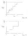
- the initial electric field ramp is characterized by a field vs. time profile comprising a plurality of discontinuous steps where each step is characterized by a particular change in electric field, ⁇ E, and time, ⁇ t.
- FIG. 1A shows a schematic depiction of such a discontinuous multi-step field vs. time profile.
- the initial electric field ramp is characterized by an electric field vs. time profile comprising a plurality of discontinuous steps wherein the values of ⁇ E and ⁇ t for each step are equal, e.g., as schematically depicted in FIG. 1A .
- an electric field vs. time profile comprising a plurality of discontinuous steps wherein the values of ⁇ E and ⁇ t for each step are equal, e.g., as schematically depicted in FIG. 1A .
- the initial electric field ramp is characterized by an electric field vs. time profile comprising a plurality of discontinuous steps wherein the values of ⁇ E and ⁇ t for each step are not equal, e.g., as schematically depicted in FIGS. 1B , 1C and 1D .
- FIG. 1B shows a schematic depiction of an initial electric field ramp comprising a discontinuous multi-step field vs. time profile in which the values of both ⁇ E and ⁇ t increase at each step.
- FIG. 1C shows a schematic depiction of an initial electric field ramp comprising an electric field vs. time profile in which the value of ⁇ E decreases at each step and the value of ⁇ T is the same for each step.
- FIG. 1B shows a schematic depiction of an initial electric field ramp comprising a discontinuous multi-step field vs. time profile in which the values of both ⁇ E and ⁇ t increase at each step.
- FIG. 1C shows a schematic depiction of an initial electric
- FIG. 1D shows a schematic depiction of an initial electric field ramp comprising an electric field vs. time profile in which the values of both ⁇ E and ⁇ t vary chaotically at each step.
- the field vs. time profile depicted schematically in FIG. 1C in which the value of ⁇ E decreases at each step is particularly preferred because it both serves to reduce the impact of the initial field ramp on peak broadening while at the same time reducing the elapsed time T of the initial electric field ramp.
- E, ⁇ E and At will vary depending upon the requirements of a particular application, preferably, when employing an initial electric field ramp comprising a discontinuous multi-step electric field vs. time profile, the value of the run field E is between about 50 V/cm and 3000 V/cm, the time per step ⁇ t is between about 5 s and 200 s, and the change in electric field per step ⁇ E is between about 1 V/cm and 200 V/cm. More preferably E is between about 80 V/cm and 320 V/cm, ⁇ t is between about 10 s and 100 s, and ⁇ E is between about 2 V/cm and 60 V/cm.
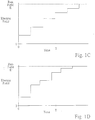
- the initial electric field ramp is characterized by a continuous electric field vs. time profile.
- the continuous electric field vs. time profile may be linear, (e.g., curve 1 in FIG 2 ), concave (e.g., curve 2 in FIG. 2 ), convex (e.g., curve 3 in FIG. 2 ), or various combinations of linear, concave, and/or convex (e.g., curve 4 in FIG.2 ).
- the continuous field vs. time profile is linear or convex due to the usual non-linearity of the temperature rise caused by Joule heating.
- the initial electric field ramp is characterized by a field vs. time profile comprising a combination of a stepped and a continuous profile.
- the particular range of values of the ramp rate of the initial electric field ramp that will result in reduced peak broadening and therefore improved separation performance will depend on a number of experimental parameters including the shape, materials and dimensions of the capillary, particularly the length of the capillary, the thermal conductivity of the separation medium and the capillary, the difference in the thermal expansion coefficient of the separation medium and the capillary, the efficiency of heat transfer between the capillary and the surrounding environment, the electrical conductivity of the separation medium, and the temperature dependence of the electrical conductivity of the separation medium.
- a smaller ramp rate will be required with (1) increasing capillary length, (2) increasing thermal expansion coefficient of the fluid separation medium, (3) increasing electrical conductivity of the fluid separation medium, (4) decreasing heat transfer coefficient between the exterior surface of the capillary and the surroundings, (5) increasing run field, and (6) increasing capillary internal diameter.
- the following procedure may be used. First, for each of a plurality of electrophoretic runs, establish a run field using an initial electric field ramp, where each run uses a different ramp rate, and where at least some of the ramp rates are less than or equal to about five V/cm-s. Next, analyze the extent of peak broadening observed for each run, e.g., by measuring a peak width at half height of a selected peak in each run. Finally, select as the preferred ramp rate one that results in a desired degree of reduction in peak broadening.
- the ramp rate of the initial electric field ramp is less than about five V/cm-s. More preferably, the ramp rate of the initial electric field ramp ranges from about 0.05 V/cm-s to about 3.0 V/cm-s. In a particularly preferred embodiment, the ramp rate ranges from about 0.1 V/cm-s to about 1.0 V/cm-s.
- the run field should be established using an initial electric field ramp having an elapsed time T of at least about ten seconds. More preferably, the run field should be established using an initial electric field ramp having an elapsed time ranging from about 20 seconds to about 500 seconds. More preferably, the run field should be established using an initial electric field ramp having an elapsed time ranging from about 500 seconds to about 4000 seconds.
- the run field E ranges between about 50 and 3000 V/cm, more preferably between about 80 and 500 V/cm.
- the run field is established using an initial electric field profile having a ramp rate which results in a reduction in an amount of peak broadening associated with the establishment of the run field of at least about 10% as compared to that found when an initial electric field ramp is not used, and more preferably a reduction in an amount of peak broadening of at least about 25%, and even more preferably a reduction in an amount of peak broadening of at least about 40%.
- the analyte species is nucleic acid and the run field is established using an initial electric field profile having a ramp rate which results in an increase in a length of read of at least about 20 nucleotides, preferably about 40 nucleotides, and more preferably about 80 nucleotides, as compared to that found when an initial electric field ramp is not used.
- the present invention comprises methods and apparatus for reducing the amount of peak broadening caused by the application of a run field in a CE separation by reducing a temperature of an environment surrounding the capillary during an initial electric field ramp by an amount sufficient to maintain the average temperature of the separation medium at a substantially constant value during such initial electric field-ramp.
- average temperature refers to a spatial average temperature where the temperature is averaged across a dimension normal to the direction of electrophoretic migration, e.g., in the case of a cylindrical capillary, the dimension is the radius.
- the temperature of the environment surrounding the capillary is reduced by an amount effective to maintain the average temperature of the separation medium located within the lumen of the capillary within about 0.4 °C of the average temperature of the separation medium prior to initiating the initial electric field ramp, more preferably to within about 0.2 °C of the average temperature of the separation medium prior to initiating the initial electric field ramp, and even more preferably to within about 0.1 °C of the average temperature of the separation medium prior to initiating the initial electric field ramp.
- the temperature of the fluid separation medium located within the lumen of the capillary is maintained constant with respect to the average temperature of the separation medium prior to initiating the initial electric field ramp by reducing the temperature of the environment surrounding the capillary by an amount sufficient to result in a displacement of the fluid separation medium at an inlet end of the capillary during the initial electric field ramp of less than about 600 um, and preferably less than about 200 ⁇ m, and more preferably less than about 20 ⁇ m.
- the temperature of the separation medium located within the lumen of the capillary is monitored by measuring the relationship between the electric field applied across the capillary and the measured current passing through the capillary.
- the conductivity of a particular separation medium varies as a function of temperature, it is possible to obtain an accurate measure of the temperature of the separation medium as the electric field is increased.
- the temperature of the separation medium begins to rise, the temperature of the surroundings is lowered using active feedback control.
- the temperature of the separation medium located within the lumen of the capillary is maintained substantially constant using a pre-programmed temperature ramp based on prior knowledge of the medium's temperature vs. electric field characteristics.
- the methods and apparatus used to carry out the CE separations according to the present invention may be performed using conventional CE methods and apparatus, as generally described elsewhere (e.g., Capillary Electrophoresis Theory and Practice, Grossman and Colburn, eds., Academic Press (1992 )).
- standard capillary tubes e.g., polyimide-coated fused silica capillary tubes
- fluid separation medium e.g., buffered polymer solutions or polymer free buffer solutions
- sample injection techniques e.g., electrokinetic or hydrodynamic injection
- automated system control devices e.g., a digital computer
- detection techniques e.g., fluorescence or optical absorbence
- CE systems used to carry out the methods of the present invention include certain non-standard features and capabilities.
- the power supply portion of a CE system for use in the present invention should be controllable by a programmable electronic controller, e.g., a personal computer, so as to allow for the control of an electric field vs. time profile of an initial electric field ramp.
- the electronic controller should be connected to a current monitor for monitoring the electric current passing through the electrophoresis capillary and be able to automatically adjust the electric field across the capillary in response to the current measurement.
- the CE system for use with the present invention should employ a temperature control system for controlling the temperature of the environment surrounding the capillary channel.
- the temperature control system should be capable of controlling the temperature of the surrounding environment to within about 0.1 °C along substantially the entire length of the capillary, be capable of changing the temperature of the surrounding environment in increments of 0.1 °C and be capable of adjusting the temperature of the surrounding environment during an initial electric field ramp, where, optionally, such changes are in response to changes in the temperature of the separation medium located in the capillary lumen.
- the 3700 system includes approximately 96 separate fused-silica separation capillaries, each capillary having an uncoated interior surface, a total length of 50 cm, an effective separation length of 50 cm, and in internal diameter of 50 ⁇ m. Fluorescence detection of the sample analytes in the 3700 system is accomplished using a sheath-flow detection system (e.g., Kambara et al., U.S. Patent No. 5,529,679 ; Dovichi et al., U.S. Patent No. 5,439,578 ).
- a sheath-flow detection system e.g., Kambara et al., U.S. Patent No. 5,529,679 ; Dovichi et al., U.S. Patent No. 5,439,578 ).
- a standard sample mixture comprising 20 single stranded DNA fragments having sizes of 35, 50, 75, 100, 139, 150, 160, 200, 250, 300, 340, 350, 400, 450, 490, 500, 550, 600, 650, and 700 nucleotides was used to characterize separation performance under various operating conditions. Each fragment of the mixture was labeled with TET dye. The sample mixture was dissolved in deionized formamide and 0.3 mM disodium EDTA to a final concentration of about 0.03 nM.
- Samples were electrokinetically injected into the capillaries by applying an electric field of 50 V/cm for 30 s while the inlet ends of the capillaries were immersed in the sample mixture.
- the separation medium used was a modified version of the commercially available ABI PRISMTM 3700 POP6 polymer (PE Biosystems, p/n 4306733) in which the denaturant was replaced with an alternative denaturant comprising urea at a concentration of either 6M or 8M.
- the POP6 polymer is a solution of a linear substituted polyacylamide.
- LOR Limit of resolution
- the single-nucleotide interval (X 2 - X 1 ) was estimated by plotting the position X of each of the 20 fragments in the sample mixture as a function of size, fitting the data points with a third-order polynomial, and determining a single-nucleotide calculated interval (X 2 - X 1 ) based on an interpolation of the resulting fitted curve.
- the peak widths at half height, W 1 and W 2 were estimated by assuming that the peak widths for fragments differing in size by a single nucleotide were the same as those of the nearest peaks of the 20 actual peaks.
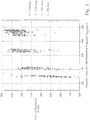
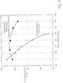
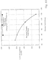
- FIGS. 3 and 4 show, at each of a number of different run fields, the LOR value for each of about 96 different electropherograms.
- the separation medium contained 8 M urea denaturant while in FIG. 4 the separation medium contained 6 M urea.
- the y-axis of each plot indicates the LOR value, while the x-axis of each plot indicates the time required for a 700 nucleotide fragment to reach the detector, T 700 .
- T 700 the average value of the LOR, LOR avg , decreased, and the standard deviation of the LOR, SD LOR , increased.
- FIGS. 5 and 6 when compared with FIGS. 3 and 4 , show the effect of a controlled initial electric field ramp on the LOR as a function of run field in two different separation media.
- the separation medium contained 8 M urea denaturant while in FIG. 6 the separation medium contained 6 M urea.
- the initial electric field ramp was 0.25 V/cm-s using a discontinuous step electric field vs. time profile where ⁇ E was 10 V/cm and ⁇ t was 40 s at each step.
- the introduction of the initial electric field ramp resulted in a substantial increase in LOR avg and decrease in SD LOR at each of the run fields studied.
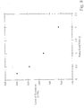
- FIGS. 7 and 8 show the effect of the ramp rate of the initial electric field ramp on LOR at two different run fields in two different separation media.
- Each of the initial electric field ramps comprised a discontinuous step electric field vs. time profile in which for each ramp rate the values of ⁇ E and ⁇ t were equal.
- FIGS. 9 and 10 demonstrate the effect of using an initial electric field ramp on LOR as a function of run field.
- the ramp rate of the initial electric field ramp was 0.25 V/cm-s in both cases where the initial electric field ramps were achieved using a discontinuous step electric field vs. time profile in which the value of ⁇ E was 10 V/cm and the value of ⁇ t was 40 s.
- the separation medium contained 8M urea and in FIG. 10 the separation medium contained 6M urea.
- the plots shown in both FIGS. 9 and 10 clearly illustrate the dramatic effect that an initial electric field ramp can have on separation performance, and also indicate that this effect becomes more pronounced at higher run fields.
Landscapes
- Health & Medical Sciences (AREA)
- Life Sciences & Earth Sciences (AREA)
- Molecular Biology (AREA)
- Chemical & Material Sciences (AREA)
- Chemical Kinetics & Catalysis (AREA)
- Electrochemistry (AREA)
- Physics & Mathematics (AREA)
- Analytical Chemistry (AREA)
- Biochemistry (AREA)
- General Health & Medical Sciences (AREA)
- General Physics & Mathematics (AREA)
- Immunology (AREA)
- Pathology (AREA)
- Measuring Or Testing Involving Enzymes Or Micro-Organisms (AREA)
- Crystals, And After-Treatments Of Crystals (AREA)
- Electrotherapy Devices (AREA)
- Measurement And Recording Of Electrical Phenomena And Electrical Characteristics Of The Living Body (AREA)
- Apparatus For Radiation Diagnosis (AREA)
- Peptides Or Proteins (AREA)
- Investigating Or Analysing Biological Materials (AREA)
- Electrochromic Elements, Electrophoresis, Or Variable Reflection Or Absorption Elements (AREA)
Claims (10)
- Procédé d'électrophorèse capillaire dans lequel des espèces d'analytes sont séparées par migration électrophorétique différentielle à travers un milieu de séparation fluide situé dans un capillaire sous l'influence d'un champ de déplacement, le procédé comprenant l'étape suivante :réduire la température de l'environnement entourant le capillaire durant une rampe de champ électrique initiale d'une quantité suffisante pour maintenir la température moyenne du milieu de séparation, durant une telle rampe de champ électrique initiale, sensiblement constante par rapport à la température moyenne du milieu de séparation avant de démarrer la rampe de champ électrique initiale,ladite rampe de champ électrique initiale étant établie de manière commandée à une vitesse de rampe prédéfinie, pour réduire une largeur de pic associée à l'établissement du champ de déplacement.
- Procédé selon la revendication 1 dans lequel la température du milieu de séparation durant une rampe de champ électrique initiale est maintenue à environ 0,4°C de la température du milieu de séparation avant de démarrer la rampe de champ électrique initiale.
- Procédé selon la revendication 1 dans lequel la température du milieu de séparation durant une rampe de champ électrique initiale est maintenue à environ 0,2°C de la température du milieu de séparation avant de démarrer la rampe de champ électrique initiale.
- Procédé selon la revendication 1 dans lequel la température du milieu de séparation durant une rampe de champ électrique initiale est maintenue à environ 0,1 °C de la température du milieu de séparation avant de démarrer la rampe de champ électrique initiale.
- Procédé selon la revendication 1 dans lequel la rampe de champ électrique initiale a pour résultat un déplacement du milieu de séparation fluide à une extrémité d'entrée du capillaire durant la rampe de champ électrique initiale inférieur à environ 600 µm .
- Procédé selon la revendication 5 dans lequel le déplacement du milieu de séparation fluide durant la rampe de champ électrique initiale est inférieur à environ 200 µm .
- Procédé selon la revendication 5 dans lequel le déplacement du milieu de séparation fluide durant la rampe de champ électrique initiale est inférieur à environ 20 µm .
- Procédé selon la revendication 1 dans lequel les espèces d'analytes sont des espèces d'acides nucléiques et dans lequel la rampe de champ électrique initiale a pour résultat une augmentation de longueur de lecture d'au moins 20 nucléotides environ.
- Procédé selon la revendication 8 dans lequel la température de l'environnement entourant le capillaire durant la rampe de champ électrique initiale est réduite de manière à maintenir une température moyenne du milieu de séparation durant une telle rampe de champ électrique initiale sensiblement constante par rapport à la température moyenne du milieu de séparation avant de démarrer la rampe de champ électrique initiale avec pour résultat une augmentation de longueur de lecture d'au moins 50 nucléotides environ.
- Procédé de réalisation d'une électrophorèse capillaire comprenant les étapes suivantes :fournir un conduit d'électrophorèse capillaire pourvu d'une lumière ;fournir un milieu de séparation fluide situé dans la lumière ;introduire une espèce d'analyte dans la lumière ; etétablir dans la lumière un champ de déplacement suffisant pour entraîner l'électrophorèse de l'espèce d'analyte ;le champ de déplacement étant établi par le procédé selon l'une quelconque des revendications précédentes.
Applications Claiming Priority (4)
| Application Number | Priority Date | Filing Date | Title |
|---|---|---|---|
| US09/361,485 US6372106B1 (en) | 1999-07-26 | 1999-07-26 | Capillary electrophoresis method and apparatus for reducing peak broadening associated with the establishment of an electric field |
| US361485 | 1999-07-26 | ||
| EP00950726A EP1196769B1 (fr) | 1999-07-26 | 2000-07-26 | Procede et appareil permettant de reduire l'elargissement de pic associe a l'etablissement d'un champ electrique |
| PCT/US2000/020349 WO2001007904A1 (fr) | 1999-07-26 | 2000-07-26 | Procede et appareil permettant de reduire une largeur de pic associe a l'etablissement d'un champ electrique |
Related Parent Applications (1)
| Application Number | Title | Priority Date | Filing Date |
|---|---|---|---|
| EP00950726A Division EP1196769B1 (fr) | 1999-07-26 | 2000-07-26 | Procede et appareil permettant de reduire l'elargissement de pic associe a l'etablissement d'un champ electrique |
Publications (3)
| Publication Number | Publication Date |
|---|---|
| EP1455183A2 EP1455183A2 (fr) | 2004-09-08 |
| EP1455183A3 EP1455183A3 (fr) | 2004-12-29 |
| EP1455183B1 true EP1455183B1 (fr) | 2020-08-26 |
Family
ID=23422250
Family Applications (2)
| Application Number | Title | Priority Date | Filing Date |
|---|---|---|---|
| EP00950726A Expired - Lifetime EP1196769B1 (fr) | 1999-07-26 | 2000-07-26 | Procede et appareil permettant de reduire l'elargissement de pic associe a l'etablissement d'un champ electrique |
| EP04013127.8A Expired - Lifetime EP1455183B1 (fr) | 1999-07-26 | 2000-07-26 | Procede et appareil permettant de reduire une largeur de pic associe a l'etablissement d'un champ electrique |
Family Applications Before (1)
| Application Number | Title | Priority Date | Filing Date |
|---|---|---|---|
| EP00950726A Expired - Lifetime EP1196769B1 (fr) | 1999-07-26 | 2000-07-26 | Procede et appareil permettant de reduire l'elargissement de pic associe a l'etablissement d'un champ electrique |
Country Status (8)
| Country | Link |
|---|---|
| US (2) | US6372106B1 (fr) |
| EP (2) | EP1196769B1 (fr) |
| JP (3) | JP2003505693A (fr) |
| AT (1) | ATE289683T1 (fr) |
| AU (1) | AU771703B2 (fr) |
| CA (1) | CA2391302C (fr) |
| DE (1) | DE60018283T2 (fr) |
| WO (1) | WO2001007904A1 (fr) |
Families Citing this family (11)
| Publication number | Priority date | Publication date | Assignee | Title |
|---|---|---|---|---|
| US6372106B1 (en) * | 1999-07-26 | 2002-04-16 | Applera Corporation | Capillary electrophoresis method and apparatus for reducing peak broadening associated with the establishment of an electric field |
| US20030143554A1 (en) * | 2001-03-31 | 2003-07-31 | Berres Mark E. | Method of genotyping by determination of allele copy number |
| WO2005043112A2 (fr) * | 2003-09-30 | 2005-05-12 | West Virginia University Research Corporation | Appareil et procede de degradation d'edman sur un dispositif microfluidique utilisant une pompe a circulation electro-osmotique |
| US20050115837A1 (en) * | 2003-12-01 | 2005-06-02 | Dean Burgi | Analyte identification in transformed electropherograms |
| US7879410B2 (en) * | 2004-06-09 | 2011-02-01 | Imra America, Inc. | Method of fabricating an electrochemical device using ultrafast pulsed laser deposition |
| KR101269741B1 (ko) * | 2006-07-04 | 2013-05-30 | 쓰리엠 이노베이티브 프로퍼티즈 캄파니 | 탄성 및 접착성을 갖는 전자기파 차단용 가스켓 |
| WO2008009310A1 (fr) * | 2006-07-17 | 2008-01-24 | Agilent Technologies, Inc. | Équilibrage d'un profil de température dans une colonne |
| JP2010530057A (ja) * | 2007-03-30 | 2010-09-02 | 富士フイルム株式会社 | 温調方法 |
| US20090203022A1 (en) * | 2008-02-07 | 2009-08-13 | Arizona Board Of Regents For And On Behalf Of Arizona State University | Analysis |
| EP2393941A2 (fr) * | 2009-02-09 | 2011-12-14 | Frederic Zenhausern | Améliorations se rapportant à une analyse |
| US20230350438A1 (en) * | 2022-04-29 | 2023-11-02 | Semes Co., Ltd. | Process measurement apparatus and method |
Citations (1)
| Publication number | Priority date | Publication date | Assignee | Title |
|---|---|---|---|---|
| EP0382426A2 (fr) * | 1989-02-06 | 1990-08-16 | Applied Biosystems, Inc. | Appareil d'électrophorèse micro-préparative |
Family Cites Families (21)
| Publication number | Priority date | Publication date | Assignee | Title |
|---|---|---|---|---|
| EP0304295A1 (fr) * | 1987-08-19 | 1989-02-22 | The Board Of Trustees Of The Leland Stanford Junior University | Méthode d'analyse électrocinétique et appareil à dissipation de chaleur |
| JP3023793B2 (ja) | 1988-02-16 | 2000-03-21 | アプライド バイオシステムズ インコーポレイテッド | 毛管電気泳動方法及びその装置 |
| US5221448A (en) * | 1990-01-25 | 1993-06-22 | Spectra-Physics Analytical, Inc. | Buffer gradient and temperature gradient capillary electrophoresis |
| US5164055A (en) * | 1990-01-29 | 1992-11-17 | Applied Biosystems, Inc. | High-viscosity polymer matrix and methods |
| JPH03239959A (ja) * | 1990-02-16 | 1991-10-25 | Bio Rad Lab Inc | 電気泳動分離法 |
| JP2722752B2 (ja) * | 1990-02-21 | 1998-03-09 | 株式会社島津製作所 | Dnaの検出方法 |
| JP3075602B2 (ja) * | 1991-09-12 | 2000-08-14 | 株式会社日立製作所 | 電気泳動装置 |
| DE9204003U1 (de) * | 1992-03-24 | 1992-07-30 | Heiß, Josef, 8172 Lenggries | Einrichtung zur Handhabung eines tragbaren Erdbohrers |
| US5296116A (en) * | 1992-06-17 | 1994-03-22 | Beckman Instruments, Inc. | Capillary electrophoresis using time-varying field strength |
| US5409586A (en) | 1992-08-26 | 1995-04-25 | Hitachi, Ltd. | Method for analyzing nucleic acid or protein and apparatus therefor |
| US5885432A (en) | 1992-11-05 | 1999-03-23 | Soane Biosciences | Un-crosslinked polymeric media for electrophoresis |
| US5385654A (en) | 1993-07-07 | 1995-01-31 | Thermo Separation Products Inc. | Controlled temperature anion separation by capillary electrophoresis |
| AU1254295A (en) | 1993-12-17 | 1995-07-03 | Perkin-Elmer Corporation, The | Uncharged polymers for separation of biomolecules by capillary electrophoresis |
| US5512158A (en) | 1995-02-28 | 1996-04-30 | Hewlett-Packard Company | Capillary electrophoresis method and apparatus for electric field uniformity and minimal dispersion of sample fractions |
| US5534123A (en) | 1995-07-10 | 1996-07-09 | Molecular Dynamics | Denaturing separation matrix having hydroxyethyl cellulose for nucleic acid electrophoresis |
| JPH09178703A (ja) * | 1995-12-26 | 1997-07-11 | Shimadzu Corp | 塩基配列決定装置 |
| EP0870194A1 (fr) | 1995-12-28 | 1998-10-14 | Novartis AG | Procede de separation electrophoretique capillaire a l'aide d'une solution polymere chargeable utilisee comme agent de separation |
| US5658446A (en) | 1996-01-22 | 1997-08-19 | Hewlett-Packard Company | Preparative capillary electrophoresis with wide-bore capillary |
| JP3418292B2 (ja) * | 1996-04-24 | 2003-06-16 | 株式会社日立製作所 | 遺伝子解析装置 |
| US5989399A (en) | 1996-09-04 | 1999-11-23 | The Research Foundation Of State University Of New York | Effective surface treatment for a new separation medium in electrophoresis |
| US6372106B1 (en) * | 1999-07-26 | 2002-04-16 | Applera Corporation | Capillary electrophoresis method and apparatus for reducing peak broadening associated with the establishment of an electric field |
-
1999
- 1999-07-26 US US09/361,485 patent/US6372106B1/en not_active Expired - Lifetime
-
2000
- 2000-07-26 AT AT00950726T patent/ATE289683T1/de not_active IP Right Cessation
- 2000-07-26 WO PCT/US2000/020349 patent/WO2001007904A1/fr not_active Ceased
- 2000-07-26 CA CA002391302A patent/CA2391302C/fr not_active Expired - Fee Related
- 2000-07-26 EP EP00950726A patent/EP1196769B1/fr not_active Expired - Lifetime
- 2000-07-26 JP JP2001512283A patent/JP2003505693A/ja not_active Withdrawn
- 2000-07-26 DE DE60018283T patent/DE60018283T2/de not_active Expired - Lifetime
- 2000-07-26 AU AU63788/00A patent/AU771703B2/en not_active Ceased
- 2000-07-26 EP EP04013127.8A patent/EP1455183B1/fr not_active Expired - Lifetime
-
2002
- 2002-02-13 US US10/075,404 patent/US7169276B2/en not_active Expired - Lifetime
-
2011
- 2011-04-19 JP JP2011093402A patent/JP2011141297A/ja not_active Withdrawn
- 2011-06-15 JP JP2011133727A patent/JP2011174951A/ja active Pending
Patent Citations (1)
| Publication number | Priority date | Publication date | Assignee | Title |
|---|---|---|---|---|
| EP0382426A2 (fr) * | 1989-02-06 | 1990-08-16 | Applied Biosystems, Inc. | Appareil d'électrophorèse micro-préparative |
Also Published As
| Publication number | Publication date |
|---|---|
| US7169276B2 (en) | 2007-01-30 |
| US6372106B1 (en) | 2002-04-16 |
| EP1455183A3 (fr) | 2004-12-29 |
| DE60018283D1 (de) | 2005-03-31 |
| JP2011141297A (ja) | 2011-07-21 |
| WO2001007904A1 (fr) | 2001-02-01 |
| EP1196769B1 (fr) | 2005-02-23 |
| CA2391302A1 (fr) | 2001-02-01 |
| JP2011174951A (ja) | 2011-09-08 |
| CA2391302C (fr) | 2005-10-18 |
| US20020100689A1 (en) | 2002-08-01 |
| JP2003505693A (ja) | 2003-02-12 |
| AU6378800A (en) | 2001-02-13 |
| AU771703B2 (en) | 2004-04-01 |
| ATE289683T1 (de) | 2005-03-15 |
| EP1196769A1 (fr) | 2002-04-17 |
| DE60018283T2 (de) | 2006-05-04 |
| EP1455183A2 (fr) | 2004-09-08 |
Similar Documents
| Publication | Publication Date | Title |
|---|---|---|
| JP2011174951A (ja) | 電場の確立に付随したピークの広幅化を少なくする方法および装置 | |
| Schmalzing et al. | DNA sequencing on microfabricated electrophoretic devices | |
| Liu et al. | Optimization of high-speed DNA sequencing on microfabricated capillary electrophoresis channels | |
| AU708739B2 (en) | Method and apparatus for reducing the distortion of a sample zone eluting from a capillary electrophoresis capillary | |
| Kleparnik et al. | DNA diagnostics by capillary electrophoresis | |
| Gao et al. | High-throughput detection of unknown mutations by using multiplexed capillary electrophoresis with poly (vinylpyrrolidone) solution | |
| Dolnı́k | DNA sequencing by capillary electrophoresis | |
| JP3418292B2 (ja) | 遺伝子解析装置 | |
| JP4342954B2 (ja) | 逆行する高親和性インターカレーション型色素を用いた核酸の電気泳動分離検出 | |
| Gelfi et al. | Temperature-programmed capillary electrophoresis for detection of DNA point mutations | |
| Han et al. | The optimization of electrophoresis on a glass microfluidic chip and its application in forensic science | |
| WO2006126427A1 (fr) | Technique et dispositif s d'electrophorese par micropuce | |
| Ugaz et al. | Cross‐linked polyacrylamide gel electrophoresis of single‐stranded DNA for microfabricated genomic analysis systems | |
| Zhu et al. | Spatial temperature gradient capillary electrophoresis for DNA mutation detection | |
| CA2506142C (fr) | Procede et appareil permettant de reduire une largeur de pic associe a l'etablissement d'un champ electrique | |
| AU689648B2 (en) | Separation of nucleic acids by capillary electrophoresis in thermal gradients in viscous polymer solutions | |
| Xue et al. | On-line nanoliter cycle sequencing reaction with capillary zone electrophoresis purification for DNA sequencing | |
| EP1406720B1 (fr) | Tampons pour electrophorese et utilisation correspondante | |
| Righetti et al. | Non-isocratic capillary electrophoresis for detection of DNA point mutations | |
| Catai et al. | Simplex optimization of electrokinetic injection of DNA in capillary electrophoresis using dilute polymer solution | |
| Schmalzing et al. | Genotyping by microdevice electrophoresis | |
| US20030138821A1 (en) | System and method for temperature gradient capillary electrophoresis | |
| JP2008134199A (ja) | 微小流体デバイス電気泳動方法および装置 | |
| Kim et al. | Capillary electrophoresis of DNA fragments using poly (ethylene oxide) as a sieving material | |
| Kaneta et al. | Miniaturized Injection Method Using Silver‐Coated Capillaries in DNA Sequencing by Multiplexed Capillary Electrophoresis |
Legal Events
| Date | Code | Title | Description |
|---|---|---|---|
| PUAI | Public reference made under article 153(3) epc to a published international application that has entered the european phase |
Free format text: ORIGINAL CODE: 0009012 |
|
| 17P | Request for examination filed |
Effective date: 20040603 |
|
| AC | Divisional application: reference to earlier application |
Ref document number: 1196769 Country of ref document: EP Kind code of ref document: P |
|
| AK | Designated contracting states |
Kind code of ref document: A2 Designated state(s): AT BE CH CY DE DK ES FI FR GB GR IE IT LI LU MC NL PT SE |
|
| PUAL | Search report despatched |
Free format text: ORIGINAL CODE: 0009013 |
|
| AK | Designated contracting states |
Kind code of ref document: A3 Designated state(s): AT BE CH CY DE DK ES FI FR GB GR IE IT LI LU MC NL PT SE |
|
| AKX | Designation fees paid |
Designated state(s): AT BE CH CY DE DK ES FI FR GB GR IE IT LI LU MC NL PT SE |
|
| 17Q | First examination report despatched |
Effective date: 20061206 |
|
| RAP1 | Party data changed (applicant data changed or rights of an application transferred) |
Owner name: LIFE TECHNOLOGIES CORPORATION |
|
| RAP1 | Party data changed (applicant data changed or rights of an application transferred) |
Owner name: LIFE TECHNOLOGIES CORPORATION |
|
| RAP1 | Party data changed (applicant data changed or rights of an application transferred) |
Owner name: LIFE TECHNOLOGIES CORPORATION |
|
| STAA | Information on the status of an ep patent application or granted ep patent |
Free format text: STATUS: EXAMINATION IS IN PROGRESS |
|
| GRAP | Despatch of communication of intention to grant a patent |
Free format text: ORIGINAL CODE: EPIDOSNIGR1 |
|
| STAA | Information on the status of an ep patent application or granted ep patent |
Free format text: STATUS: GRANT OF PATENT IS INTENDED |
|
| INTG | Intention to grant announced |
Effective date: 20180323 |
|
| GRAS | Grant fee paid |
Free format text: ORIGINAL CODE: EPIDOSNIGR3 |
|
| GRAA | (expected) grant |
Free format text: ORIGINAL CODE: 0009210 |
|
| STAA | Information on the status of an ep patent application or granted ep patent |
Free format text: STATUS: THE PATENT HAS BEEN GRANTED |
|
| REG | Reference to a national code |
Ref country code: DE Ref legal event code: R071 Ref document number: 60049979 Country of ref document: DE |
|
| AC | Divisional application: reference to earlier application |
Ref document number: 1196769 Country of ref document: EP Kind code of ref document: P |
|
| AK | Designated contracting states |
Kind code of ref document: B1 Designated state(s): AT BE CH CY DE DK ES FI FR GB GR IE IT LI LU MC NL PT SE |
|
| REG | Reference to a national code |
Ref country code: GB Ref legal event code: FG4D |
|
| REG | Reference to a national code |
Ref country code: CH Ref legal event code: EP Ref country code: CH Ref legal event code: PL |
|
| REG | Reference to a national code |
Ref country code: NL Ref legal event code: MK Effective date: 20200725 |
|
| REG | Reference to a national code |
Ref country code: DE Ref legal event code: R096 Ref document number: 60049979 Country of ref document: DE |
|
| REG | Reference to a national code |
Ref country code: AT Ref legal event code: REF Ref document number: 1306851 Country of ref document: AT Kind code of ref document: T Effective date: 20200915 |
|
| REG | Reference to a national code |
Ref country code: IE Ref legal event code: FG4D |
|
| REG | Reference to a national code |
Ref country code: GB Ref legal event code: PE20 Expiry date: 20200725 |
|
| REG | Reference to a national code |
Ref country code: IE Ref legal event code: MK9A |
|
| REG | Reference to a national code |
Ref country code: BE Ref legal event code: MK Effective date: 20200726 |
|
| PG25 | Lapsed in a contracting state [announced via postgrant information from national office to epo] |
Ref country code: SE Free format text: LAPSE BECAUSE OF FAILURE TO SUBMIT A TRANSLATION OF THE DESCRIPTION OR TO PAY THE FEE WITHIN THE PRESCRIBED TIME-LIMIT Effective date: 20200826 Ref country code: PT Free format text: LAPSE BECAUSE OF FAILURE TO SUBMIT A TRANSLATION OF THE DESCRIPTION OR TO PAY THE FEE WITHIN THE PRESCRIBED TIME-LIMIT Effective date: 20201228 Ref country code: GR Free format text: LAPSE BECAUSE OF FAILURE TO SUBMIT A TRANSLATION OF THE DESCRIPTION OR TO PAY THE FEE WITHIN THE PRESCRIBED TIME-LIMIT Effective date: 20201127 |
|
| REG | Reference to a national code |
Ref country code: AT Ref legal event code: MK05 Ref document number: 1306851 Country of ref document: AT Kind code of ref document: T Effective date: 20200826 |
|
| PG25 | Lapsed in a contracting state [announced via postgrant information from national office to epo] |
Ref country code: DK Free format text: LAPSE BECAUSE OF FAILURE TO SUBMIT A TRANSLATION OF THE DESCRIPTION OR TO PAY THE FEE WITHIN THE PRESCRIBED TIME-LIMIT Effective date: 20200826 |
|
| REG | Reference to a national code |
Ref country code: DE Ref legal event code: R097 Ref document number: 60049979 Country of ref document: DE |
|
| PG25 | Lapsed in a contracting state [announced via postgrant information from national office to epo] |
Ref country code: ES Free format text: LAPSE BECAUSE OF FAILURE TO SUBMIT A TRANSLATION OF THE DESCRIPTION OR TO PAY THE FEE WITHIN THE PRESCRIBED TIME-LIMIT Effective date: 20200826 Ref country code: AT Free format text: LAPSE BECAUSE OF FAILURE TO SUBMIT A TRANSLATION OF THE DESCRIPTION OR TO PAY THE FEE WITHIN THE PRESCRIBED TIME-LIMIT Effective date: 20200826 |
|
| PLBE | No opposition filed within time limit |
Free format text: ORIGINAL CODE: 0009261 |
|
| STAA | Information on the status of an ep patent application or granted ep patent |
Free format text: STATUS: NO OPPOSITION FILED WITHIN TIME LIMIT |
|
| PG25 | Lapsed in a contracting state [announced via postgrant information from national office to epo] |
Ref country code: IT Free format text: LAPSE BECAUSE OF FAILURE TO SUBMIT A TRANSLATION OF THE DESCRIPTION OR TO PAY THE FEE WITHIN THE PRESCRIBED TIME-LIMIT Effective date: 20200826 |
|
| 26N | No opposition filed |
Effective date: 20210527 |