EP1455215A2 - Beleuchtungseinrichtung für ein Mikroskop - Google Patents
Beleuchtungseinrichtung für ein Mikroskop Download PDFInfo
- Publication number
- EP1455215A2 EP1455215A2 EP04003065A EP04003065A EP1455215A2 EP 1455215 A2 EP1455215 A2 EP 1455215A2 EP 04003065 A EP04003065 A EP 04003065A EP 04003065 A EP04003065 A EP 04003065A EP 1455215 A2 EP1455215 A2 EP 1455215A2
- Authority
- EP
- European Patent Office
- Prior art keywords
- microscope
- deflection
- illumination
- observation
- lighting
- Prior art date
- Legal status (The legal status is an assumption and is not a legal conclusion. Google has not performed a legal analysis and makes no representation as to the accuracy of the status listed.)
- Granted
Links
Images


Classifications
-
- G—PHYSICS
- G02—OPTICS
- G02B—OPTICAL ELEMENTS, SYSTEMS OR APPARATUS
- G02B27/00—Optical systems or apparatus not provided for by any of the groups G02B1/00 - G02B26/00, G02B30/00
- G02B27/10—Beam splitting or combining systems
- G02B27/14—Beam splitting or combining systems operating by reflection only
- G02B27/144—Beam splitting or combining systems operating by reflection only using partially transparent surfaces without spectral selectivity
-
- A—HUMAN NECESSITIES
- A61—MEDICAL OR VETERINARY SCIENCE; HYGIENE
- A61B—DIAGNOSIS; SURGERY; IDENTIFICATION
- A61B3/00—Apparatus for testing the eyes; Instruments for examining the eyes
- A61B3/10—Objective types, i.e. instruments for examining the eyes independent of the patients' perceptions or reactions
- A61B3/13—Ophthalmic microscopes
- A61B3/132—Ophthalmic microscopes in binocular arrangement
-
- G—PHYSICS
- G02—OPTICS
- G02B—OPTICAL ELEMENTS, SYSTEMS OR APPARATUS
- G02B21/00—Microscopes
- G02B21/06—Means for illuminating specimens
- G02B21/08—Condensers
-
- G—PHYSICS
- G02—OPTICS
- G02B—OPTICAL ELEMENTS, SYSTEMS OR APPARATUS
- G02B27/00—Optical systems or apparatus not provided for by any of the groups G02B1/00 - G02B26/00, G02B30/00
- G02B27/10—Beam splitting or combining systems
- G02B27/14—Beam splitting or combining systems operating by reflection only
- G02B27/143—Beam splitting or combining systems operating by reflection only using macroscopically faceted or segmented reflective surfaces
-
- G—PHYSICS
- G02—OPTICS
- G02B—OPTICAL ELEMENTS, SYSTEMS OR APPARATUS
- G02B27/00—Optical systems or apparatus not provided for by any of the groups G02B1/00 - G02B26/00, G02B30/00
- G02B27/10—Beam splitting or combining systems
- G02B27/14—Beam splitting or combining systems operating by reflection only
- G02B27/145—Beam splitting or combining systems operating by reflection only having sequential partially reflecting surfaces
Definitions
- the present invention relates to a lighting device for a microscope, in particular a surgical microscope, according to the preamble of claim 1.
- Use lighting equipment for surgical microscopes usually an illumination beam path that is related to an angle in the range of the observation beam path of about 6 ° (so-called 6 ° lighting). hereby one avoids an undesirable shadow formation, which at larger angles between the observation beam path and the illumination beam path would occur.
- Ophthalmic surgery has other special requirements to the illumination of a microscope. First you get a sufficient plasticity of the picture with one Illumination angle of again about 6 °. However, it is for certain eye surgery observations or interventions necessary to create the so-called red reflex. in this connection the pupil of the operated eye shines through from the Scattered light retina reddish. This type of lighting is for example in cataract surgeries from of great importance, since here tissue remains against the light of the Red reflexes are particularly easy to see.
- the red reflex generation requires smaller angles between the observation beam path and the illuminating beam path, wherein here angles in the range of 0 ° - 2 ° are preferred (so-called 2 ° illumination).
- Surgical microscopes which use two pairs of stereoscopic Observation beam paths for a main surgeon or a co-observer are often trained insofar as the red reflex for the Main surgeon very good, but inadequate for the co-observer can be observed. This gets dependent from its positioning, either to the right or to the left of Main surgeon only in one of his two observation channels a good red reflex. This affects the stereoscopic observation.
- DE 040 28 605 describes a lighting device for an operating microscope with an illumination system that arranged outside the optical axis of the microscope objective and the area of operation parallel to the lens axis illuminated through the microscope objective, and a deflection element on the side of the microscope objective facing away from the object, which the operation area with a Fraction of the illuminating light along the lens axis illuminated, known.
- This lighting device draws is characterized in that the lighting system on the lens side is equipped with a reflection element, which the illuminating light parallel to the lens axis to the microscope lens reflected and that the deflecting element the operation area opposite at an angle of inclination illuminated the lens axis, which is smaller than the angle of inclination, under which the reflection element the area of operation illuminated.
- the larger angle of inclination is here preferably 6 °, the smaller one can be varied from 0 ° to 6 °.
- a disadvantage of this construction is that that the radiation reflected by the deflecting element is marginal radiation the lighting pupil of the lighting system is, so that with a near-axis lighting, for example at an angle of 2 ° to the observation beam path, a relatively inhomogeneous and vignetted illumination of the Illuminated field can be observed.
- Additional lighting devices for surgical microscopes are known from DE 196 50 773 A1 and EP 1 109 046 A1. These lighting devices also use for the near-axis lighting edge rays of the lighting pupil of the lighting device so that it too the disadvantages mentioned.
- the invention aims to provide a lighting device for to provide a microscope which is opposite conventional devices of this type a more homogeneous and Vignetting-free illumination of the illuminated field enables. At the same time, one strives to be as small as possible to provide building lighting equipment, so the overall height of a microscope is not undesirable Way is enlarged.
- the invention is a particularly homogeneous and vignetting-free Illumination of the illuminated field of the microscope ensures because through the use of deflection elements (to redirect light from a lighting system an object to be observed), which is called physical Beam splitters are formed, essentially the full Cross section of the illumination pupil of all mirror elements or deflecting elements.
- deflection elements to redirect light from a lighting system an object to be observed
- physical Beam splitters are formed, essentially the full Cross section of the illumination pupil of all mirror elements or deflecting elements.
- Both Lighting devices according to the prior art only small, fully reflective segments the deflection elements for deflecting the edge areas of the illumination pupils used. According to the beam splitters the prior art is therefore geometric Beam splitter.
- the deflection device according to the invention it is in particular possible to use the individual deflection elements to position along a single optical axis whereby the overall height of a microscope is advantageously reduced can be.
- the deflection device has at least one lighting device three deflection elements.
- the most preferred Design with three deflection elements enables, for example 6 ° illumination for surgical microscopes, + 2 ° lighting and -2 ° lighting.
- a simultaneous + 2 ° and -2 ° lighting is possible.
- This lighting option is particularly evident in the red reflex operational techniques as advantageous, at which can cause the eye to roll.
- phacoemulsification at simultaneous + 2 ° and -2 ° lighting is guaranteed, that the operator has no settings while working on the microscope. It is also a simultaneous one + 2 °, -2 ° and 6 ° lighting possible, as well as any other combinations, for example through use of correspondingly positioned panels can be.
- At least one of the deflection elements is expedient at least partially fully mirrored. through This measure can light that is on the fully mirrored Areas strikes completely on the observed Object can be directed, making the illuminance advantageous can be influenced. Furthermore, in this way Overlaps between the observation beam paths of the Microscope and the fully mirrored areas in easier Be constructed way. Such overlaps are for certain eye surgery applications, for example to provide or adjust the red reflex necessary.
- Lighting is the deflection device as prism combination with partially reflecting surfaces educated.
- prism systems prove to be adjustable with relatively little effort.
- the deflection device accordingly to position positioned, partially reflecting mirrors.
- the lighting device is the deflection device as a uniform or one-piece prism block educated. With such a uniform prism block is the adjustment work required for microscope assembly limited to a minimum. Such a prism block also proves to be very robust in microscope operation.
- the deflection device two prism blocks separated from each other having.
- the observation beam paths are, for example impairing adhesive joints between the respective prisms of the deflection device, which can lead to double images or reflections, essentially preventable.
- the deflection elements also as correspondingly reflecting or transmitting Mirror, which is positioned independently of prism blocks are, could be trained.
- Microscope this is designed as a stereomicroscope. It is particularly preferred here that the stereomicroscope two observation beam paths for a main surgeon and two further observation beam paths for an assistant having. Especially with such a stereo microscope with observation beam paths for a main surgeon and an assistant can be compared to conventional Microscopes of this type for both the main surgeon as well as the wizard red reflex properties in set as desired. The exploitation essentially of the entire illumination pupil leads to that vignetting can be largely avoided, and for both the primary observer and the assistant a homogeneous light field can be provided.
- the microscope according to the invention expediently has Apertures with which the illuminating beam paths are optional can be switched on or off. hereby it is possible, for example, a 0 ° lighting in the essentially turn off so that the emergence of the red reflex can also be avoided if necessary.
- the Deflection device with respect to the optical axis of the main microscope objective is displaceable.
- a transverse displacement perpendicular to the optical Axis of the main lens is provided.
- the microscope has a deflection device with a trained as a physical beam splitter Deflection element, and another reflective Deflection element, wherein glass blocks are also provided are positioned such that the observation beam paths through the microscope.
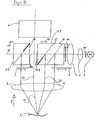
- FIG. 1 shows a preferred embodiment of the invention Microscope labeled 100 in total.
- the microscope 100 has a main objective 2 and a magnification system 9, in particular in the form of a zoom system.
- the axis of the overall optical system formed from the main objective 2 and the magnification system 9 is designated by 11.
- the observation channels of the microscope 100 run parallel to this axis 11.
- this axis 11 in the main objective 2 has a kink caused by the asymmetrical positioning of the magnification system 9 with respect to the main objective 2.
- This asymmetrical positioning of the main objective 2 and the magnification system 9 proves to be advantageous for certain applications.
- the prism block 8 has a total of 3 as mirrored surfaces trained deflection elements 16, 17, 18.
- the deflection element 16 is complete, the deflection element 17 at least partially designed as a physical beam splitter. That is, in the illustration of FIG. 1 of right on the deflecting elements 16, 17 bundle cross-section of the (shown schematically) light beam 12a from the light source 3 remains unchanged. The breakdown of the light beam 12a takes place uniformly over the entire Cross section of the deflection elements 16, 17. It can be seen that that along the illumination axis 12 of the deflection device 8 incident light bundles 12a on the deflection element 16 into a first partial beam 13, which reflects , and a second partial beam 12b, which is transmitted, is divided. Partial beam 13 provides a 6 ° illumination after passing through the main lens 2 available for object 1.
- the partial beam transmitted at the deflection element 16 12b is also in turn on the second deflection element 17 partially reflected and transmitted. That reflected Partial beam is at 14, the transmitted Partial beams denoted by 12c. That reflected Partial beam 14 initially runs essentially parallel to the partial beam 13. The partial beam 14 passes after passing through the main lens 2 + 2 ° lighting of object 1 available.
- the partial beam 15 represents a -2 ° illumination of the object 1 by means of further provided panels 6, 7 Partial beams 13, 14, 15 switched off or partially be dimmed. This can be used, for example, at Observation of an eye may cause disruptive corneal reflexes avoided, or the contrast of the red reflex be improved.
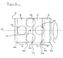
- figure 2 shows a projection of the deflection elements on the underside 8a of the deflection device 8.
- the respective lower edges 16a, 17a, 18a of the deflection elements 16, 17, 18, which actually run in this bottom 8a are with solid lines.
- the upper edges 16b, 17b, 18b of the deflection elements 16, 17, 18, which are in the top 8b, are shown with dashed lines.
- FIG. 2 shows the observation beam paths of the Microscope, two observation beam paths 22a, 22b for a main observer or operator and two observation beam paths 23a, 23b for a co-observer or Assistants are provided.
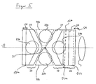
- the deflection elements 17, 18 partially fully mirrored, where regions of the deflection elements 17, 18 that are not fully mirrored either semi-translucent or partially mirrored or transparent can be trained. This fact will now explained with reference to Figure 3.
- the deflection elements 17, 18, as shown in Figure 3 are characterized by the fact that they are only partially are fully mirrored.
- the bottom and top edges of the deflecting elements 17, 18 are again 17a or 17b and 18a and 18b respectively.
- Between the edges 17a, 17b of the deflection element 17 can be seen in the one shown Projection arrow-shaped area 19, which has a lower edge 19a and an upper edge 19b.
- This area 19 is in turn the fully mirrored area of the deflecting element 17.
- the Area to the right of the upper edge 19b, here designated 17c, and the area to the left of the lower edge 19a, referred to here as area 17d, is transparent, so the corresponding overlap areas between the observation channels 23b and 22a, 22b and the fully mirrored area 19 are reduced. So is an essentially unimpeded observation through the observation channels 22a, 22b and 23b guaranteed.
- Deflection element 18 is designed in an analogous manner, wherein here the completely mirrored area again at 20 is designated. In comparison to the embodiment according to FIG 2 you can see that the overlap area between the full mirroring area 20 and the observation channel 23a is greatly reduced, so that overall a stereoscopic Observation for a co-observer using the beam paths 23a, 23b is provided. Also the areas of overlap between the fully mirrored area 19 and the observation beam paths 22a, 22b reduced compared to the embodiment according to FIG. 2.
- FIG. 4 Another preferred embodiment of the invention Lighting device will now be referenced to FIG Figures 4 and 5 shown.
- FIG. 4 corresponds to that shown there Microscope essentially that shown in FIG. so that the same components with the same reference number are designated.
- the microscope according to FIG. 4 differs differs from the microscope according to FIG. 1 in that the deflection device is not a one-piece prism block, but in the form of two prism blocks 48, 49, which are physical are separate from one another, is formed.
- glass blocks In place of the separated sections 30a, 30b it is possible to use glass blocks, which ensures can be that both the main surgeon and the Observers find the same observation conditions. It is also possible to complete such glass blocks omit and additionally optically imaging lenses in the observation beam path of co-observers or Main surgeon to compensate for any that may arise Focus difference between the observation beam path of the main surgeon or the co-observer.
- the +/- 2 ° lighting serves to Optimal observation of the red reflex. Switching the lighting from a + 2 ° lighting to a -2 ° lighting should serve in particular the red reflex then improve when the patient's eye, for example rolled away from the surgeon during phacoemulsification becomes. With conventional microscopes it was necessary to use one +/- 2 ° mirror active in the corresponding position by pressing a rotary knob. According to the invention is a simultaneous + 2 and -2 ° lighting in simple Can be provided in such a way that the surgeon has no such activities distracting from the actual operation must be expected.
- the + 2 ° lighting is usually used to observe the red reflex with the patient's eye centered.
- the - 2 ° lighting is particularly advantageous when the patient's eye is off-center used.
- the lighting device according to the invention stands out through a very easy handling in the practical Application off. Because of the summary of the deflection elements to a single prism block or to two prism blocks can do adjustment work to create optimal clearances between the deflection elements 16, 17, 18 completely or largely avoided. In the embodiment 1 and 4, it is possible to use the prism block 8 or the two prism blocks 48, 49 along the axis 12 move against each other, like this with the double arrows 25, 58, 59 is clearly shown.
- the prism block according to FIG. 1 can be produced in particular by using two essentially identical prism blocks which are rotated rotationally symmetrically with respect to one another, a parallelogram block being inserted between the rotationally symmetrically offset prisms. It should be noted that in the illustrated embodiments of the microscope, the observation channels are arranged essentially symmetrically about the observation axis 11. This observation axis does not necessarily correspond to the central axis or optical axis of the main objective 2.
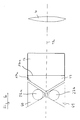
- FIG. 6 shows a further embodiment of the deflection device according to the invention in one direction accordingly the direction of the arrows P from FIG. 1 or FIG 4 shown.
- the one shown in Figure 6 as a prism block trained deflection device is with two deflection elements 16, 17 formed, wherein deflecting element 16 as physical beam splitter, and deflecting element 17 essentially is fully mirrored.
- Corresponding the representation according to FIGS. 1-5 shows the lower edges 16a and 17a of the deflection elements 16, 17. On one The corresponding upper edges are not shown here.
- the respective deflection elements or deflection surfaces 16a, 17a extend obliquely to the right into the plane of the drawing.
- Deflection element 16 serves analogously to that already described Embodiments of the lighting device according to the invention to provide 6 ° lighting, and deflection element 17 to provide a + 2 ° illumination.
- 6 to the left of the observation beam paths run the deflection element 17 22a, 22b of the stereomicroscope.
- Such a deflection device also builds shorter in the direction of the axis 12 shown than conventional deflection devices, especially since the to the two observation beam paths 22a, 22b Part of the deflection device to achieve an optimal and vignetting-free observation tapered is.
- the glass blocks with the glued as a prism block deflector It is also possible to separate the glass blocks from the Deflection device to be provided so that it only when needed can be used.
- FIG. 6 a representation of a Light source is dispensed with. It is also related with one provided between the light source and the deflection device optical system only schematically a lens, which is also denoted here by 4.
Landscapes
- Physics & Mathematics (AREA)
- General Physics & Mathematics (AREA)
- Optics & Photonics (AREA)
- Life Sciences & Earth Sciences (AREA)
- Health & Medical Sciences (AREA)
- Heart & Thoracic Surgery (AREA)
- Animal Behavior & Ethology (AREA)
- Ophthalmology & Optometry (AREA)
- Engineering & Computer Science (AREA)
- Biomedical Technology (AREA)
- Spectroscopy & Molecular Physics (AREA)
- Medical Informatics (AREA)
- Molecular Biology (AREA)
- Surgery (AREA)
- Biophysics (AREA)
- General Health & Medical Sciences (AREA)
- Public Health (AREA)
- Veterinary Medicine (AREA)
- Chemical & Material Sciences (AREA)
- Analytical Chemistry (AREA)
- Microscoopes, Condenser (AREA)
- Eye Examination Apparatus (AREA)
Abstract
Description
Licht zur Beleuchtung eines zu beobachtenden Objektes 1 gelangt von einer Lichtquelle 3 über eine als Prismenblock 8 ausgebildete Umlenkeinrichtung auf das Objekt 1. Zwischen der Lichtquelle 3 und der Umlenkeinrichtung 8 sind beispielhaft zwei Linsen 4, 5 sowie zwei Blenden 28, 29 vorgesehen. Als Lichtquelle 3 sind alle üblichen Lichtquellen, insbesondere kohärente und/oder inkohärente Lichtquellen, wie beispielsweise Glühbirnen, Faserbeleuchtungen, Entladungslampen, Laser usw. einsetzbar.
Es sei angemerkt, dass in den dargestellten Ausführungsformen des Mikroskops die Beobachtungskanäle im wesentlichen symmetrisch um die Beobachtungsachse 11 angeordnet sind. Diese Beobachtungsachse entspricht nicht notwendigerweise der Mittelachse bzw. optischen Achse des Hauptobjektivs 2.
- 1
- Objekt
- 2
- Hauptobjektiv
- 3
- Lichtquelle
- 4, 5
- Linsen
- 6, 7
- Blenden
- 8
- Umlenkeinrichtung (Prismenblock)
- 8a
- Unterseite der Umlenkeinrichtung
- 8b
- Oberseite der Umlenkeinrichtung
- 9
- Vergrößerungssystem
- 11
- optische Achse
- 12
- Achse der Umlenkeinrichtung
- 12a, b, c
- Teilstrahlenbündel
- 14, 15, 16
- Teilstrahlenbündel
- 16, 17, 18
- Umlenkelemente
- 16a, 17a, 18a
- Unterkanten der Umlenkelemente
- 16b, 17b, 18b
- Oberkante der Umlenkelemente
- 17e
- Blech
- 17f
- Oberflächenbelegungen
- 19, 20
- verspiegelte Bereiche der Umlenkelemente 17, 18
- 22a, 22b
- Beobachtungsstrahlengänge Hauptbeobachter
- 23a, 23b
- Beobachtungsstrahlengänge Mitbeobachter
- 24
- verspiegelter Bereich des Umlenkelements 16
- 25
- Doppelpfeil
- 28, 29
- Blenden
- 30a, 30b
- keilartige Blöcke
- 48, 49
- Umlenkeinrichtung (Prismenblöcke)
- 58, 59
- Doppelpfeile
- 60, 61
- Glasblöcke
- 100
- Mikroskop
Claims (14)
- Beleuchtungseinrichtung für ein wenigstens einen Be obachtungsstrahlengang aufweisendes Mikroskop, insbesondere ein Operationsmikroskop, mit einem Beleuchtungssystem (3, 4, 5, 28, 29) und einer Umlenkeinrichtung (8; 48, 49) zum Umlenken von aus dem Beleuchtungssystem austretendem Licht auf ein zu beobachtendes Objekt, insbesondere ein zu operierendes Auge, wobei die Umlenkeinrichtung eine Beleuchtung des Objektes unter verschiedenen Beleuchtungswinkeln bezüglich des wenigstens einen Beobachtungsstrahlengangs gestattet,
dadurch gekennzeichnet, dass
die Umlenkeinrichtung (8; 48, 49) zwei wenigstens teilweise als physikalische Strahlenteiler ausgebildete Umlenkelemente (16, 17) aufweist. - Beleuchtungseinrichtung nach Anspruch 1, dadurch gekennzeichnet, dass die Umlenkeinrichtung drei Umlenkelemente (16, 17,18) aufweist.
- Beleuchtungseinrichtung nach einem der vorstehenden Ansprüche oder dem Oberbegriff des Anspruchs 1, dadurch gekennzeichnet, dass zwei Umlenkelemente derart ausgebildet sind, dass eine gleichzeitige +2°- und -2°-Beleuchtung des Objektes möglich ist.
- Beleuchtungseinrichtung nach einem der Ansprüche 1 bis 3, dadurch gekennzeichnet, dass wenigstens eines der Umlenkelemente(17, 18) wenigstens teilweise vollverspiegelt ausgebildet ist.
- Beleuchtungseinrichtung nach einem der vorstehenden Ansprüche, dadurch gekennzeichnet, dass die Umlenkeinrichtung als teilreflektierende Flächen aufweisende Prismenkombination (8; 48, 49) ausgebildet ist.
- Beleuchtungseinrichtung nach einem der vorstehenden Ansprüche, dadurch gekennzeichnet, dass die Umlenkeinrichtung als einheitlicher Prismenblock (8) ausgebildet ist.
- Beleuchtungseinrichtung nach einem der vorstehenden Ansprüche 1 bis 5, dadurch gekennzeichnet, dass die Umlenkeinrichtung wenigstens zwei räumlich voneinander getrennte Prismenblöcke (48, 49) aufweist.
- Mikroskop, insbesondere Stereomikroskop, mit einem Hauptobjektiv (2) und einem diesem nachgeschalteten Vergrößerungssystem (9), gekennzeichnet durch eine Beleuchtungseinrichtung nach einem der vorstehenden Ansprüche.
- Mikroskop nach Anspruch 8, dadurch gekennzeichnet, dass es vier Beobachtungskanäle (22a, 22b, 23a, 23b) aufweist.
- Mikroskop nach einem der Ansprüche 8 oder 9, gekennzeichnet durch Blenden (6, 7) zum wahlweisen Ein- und Ausschalten von Beleuchtungsstrahlengängen.
- Mikroskop nach einem der Ansprüche 8 bis 10, dadurch gekennzeichnet, dass die Umlenkeinrichtung (8; 48, 49) bezüglich einer durch Anordnung von Hauptobjektiv (2) und Vergrößerungssystem (9) relativ zueinander definierten optischen Achse des Mikroskops querverschiebbar ist.
- Mikroskop nach einem der Ansprüche 9 bis 11, gekennzeichnet durch in die Beobachtungskanäle (22a, 22b, 23a, 23b) einbringbare Glasblöcke.
- Mikroskop, insbesondere Stereomikroskop, mit einer Beleuchtungseinrichtung nach dem Oberbegriff des Patentanspruchs 1, wobei die Umlenkeinrichtung ein als physikalischer Strahlenteiler ausgebildetes Umlenkelement (16) und ein weiteres, reflektierend ausgebildetes Umlenkelement (17) aufweist, gekennzeichnet durch wenigstens einen in die Beobachtungsstrahlenkanäle (22a, 22b) des Mikroskops einbringbaren Glasblock (60, 61).
- Mikroskop nach Anspruch 13, dadurch gekennzeichnet, dass der wenigstens eine Glasblock (60, 61) mit der Umlenkeinrichtung verklebt ist.
Applications Claiming Priority (2)
| Application Number | Priority Date | Filing Date | Title |
|---|---|---|---|
| DE10311000A DE10311000C5 (de) | 2003-03-06 | 2003-03-06 | Beleuchtungseinrichtung für ein Mikroskop |
| DE10311000 | 2003-03-06 |
Publications (4)
| Publication Number | Publication Date |
|---|---|
| EP1455215A2 true EP1455215A2 (de) | 2004-09-08 |
| EP1455215A3 EP1455215A3 (de) | 2005-01-19 |
| EP1455215B1 EP1455215B1 (de) | 2008-06-11 |
| EP1455215B2 EP1455215B2 (de) | 2012-01-11 |
Family
ID=32797912
Family Applications (1)
| Application Number | Title | Priority Date | Filing Date |
|---|---|---|---|
| EP04003065A Expired - Lifetime EP1455215B2 (de) | 2003-03-06 | 2004-02-11 | Beleuchtungseinrichtung für ein Mikroskop |
Country Status (4)
| Country | Link |
|---|---|
| US (1) | US7142359B2 (de) |
| EP (1) | EP1455215B2 (de) |
| JP (2) | JP4651958B2 (de) |
| DE (2) | DE10311000C5 (de) |
Cited By (2)
| Publication number | Priority date | Publication date | Assignee | Title |
|---|---|---|---|---|
| EP3136150A1 (de) * | 2015-08-24 | 2017-03-01 | Leica Instruments (Singapore) Pte. Ltd. | Beleuchtungs- und beobachtungssystem für ein augenmikroskop, augenmikroskop und mikroskopieverfahren mit vier roten rückstrahlern zur beobachtung von pupillen |
| EP3136149A1 (de) * | 2015-08-24 | 2017-03-01 | Leica Instruments (Singapore) Pte. Ltd. | Beleuchtungs- und beobachtungssystem für ein ophthalmisches mikroskop, ophthalmisches mikroskop mit solch einem system und mikroskopieverfahren |
Families Citing this family (16)
| Publication number | Priority date | Publication date | Assignee | Title |
|---|---|---|---|---|
| US7167315B2 (en) * | 2004-04-20 | 2007-01-23 | Microvision, Inc. | Apparatus and method for combining multiple electromagnetic beams into a composite beam |
| DE102004050651A1 (de) * | 2004-08-06 | 2006-03-16 | Carl Zeiss Surgical Gmbh | Beleuchtungseinrichtung sowie Beobachtungseinrichtung |
| JP4786215B2 (ja) * | 2005-04-04 | 2011-10-05 | 株式会社トプコン | 手術用顕微鏡装置 |
| EP1837695A1 (de) * | 2006-03-22 | 2007-09-26 | Carl Zeiss SMT AG | Katadioptrisches Abbildungssystem mit Strahlteiler |
| US7850338B1 (en) | 2006-09-25 | 2010-12-14 | Microscan Systems, Inc. | Methods for directing light |
| US7852564B2 (en) | 2006-09-27 | 2010-12-14 | Microscan Systems, Inc. | Devices and/or systems for illuminating a component |
| EP2203734B1 (de) * | 2007-10-16 | 2018-02-21 | Koninklijke Philips N.V. | Beleuchrungsvorrichtung und -system zur herstellung und integration kompakter beleuchtungsschemata |
| DE102009028229B3 (de) * | 2009-06-10 | 2010-12-09 | Leica Instruments (Singapore) Pte. Ltd. | Beleuchtungseinrichtung für ein Operationsmikroskop |
| JP5347752B2 (ja) * | 2009-06-23 | 2013-11-20 | 株式会社ニコン | 実体顕微鏡 |
| DE102009036913B4 (de) * | 2009-08-11 | 2016-01-28 | Carl Zeiss Meditec Ag | Operationsmikroskop mit Beleuchtungseinrichtung |
| DE102009046449B3 (de) * | 2009-11-06 | 2011-05-12 | Leica Instruments (Singapore) Pte. Ltd. | Stereomikroskop |
| DE102010003295B4 (de) | 2010-03-25 | 2014-09-04 | Leica Microsystems (Schweiz) Ag | Beleuchtungseinrichtung für ein Operationsmikroskop |
| DE102010028169A1 (de) | 2010-04-23 | 2011-10-27 | Leica Microsystems (Schweiz) Ag | Beleuchtungseinrichtung für ein Operationsmikroskop |
| DE102012213369B4 (de) * | 2012-07-30 | 2016-01-28 | Leica Microsystems (Schweiz) Ag | Stereomikroskop mit vier Beobachtungskanälen |
| JP2017079904A (ja) * | 2015-10-26 | 2017-05-18 | ソニー株式会社 | 手術顕微鏡、画像処理装置、及び、画像処理方法 |
| TWI845693B (zh) | 2019-07-11 | 2024-06-21 | 以色列商奧寶科技有限公司 | 用於檢驗之光學設備及方法 |
Family Cites Families (20)
| Publication number | Priority date | Publication date | Assignee | Title |
|---|---|---|---|---|
| FR2061657B1 (de) * | 1969-09-11 | 1974-05-24 | Tokyo Shibaura Electric Co | |
| DE3327672C2 (de) * | 1983-07-30 | 1986-02-20 | Fa. Carl Zeiss, 7920 Heidenheim | Koaxiale Auflicht-Hellfeldbeleuchtung für Stereomikroskope |
| DE3833876A1 (de) * | 1988-10-05 | 1990-04-12 | Zeiss Carl Fa | Zwei optisch-mechanisch gekoppelte operationsmikroskope mit koaxialer beleuchtung |
| JP3011950B2 (ja) * | 1989-08-23 | 2000-02-21 | 株式会社トプコン | 手術用顕微鏡 |
| DE9017990U1 (de) | 1990-09-08 | 1993-06-24 | Fa. Carl Zeiss, 7920 Heidenheim | Beleuchtungseinrichtung für ein Operationsmikroskop |
| DE4331635C2 (de) * | 1992-12-22 | 2001-03-15 | Zeiss Carl Fa | Beleuchtungseinrichtung für ein Operationsmikroskop mit optisch-mechanisch gekoppelten Beobachtertuben |
| JP3371917B2 (ja) * | 1993-07-12 | 2003-01-27 | 株式会社ニコン | 防振機能を備えたズームレンズ |
| DE4417273C2 (de) * | 1994-05-18 | 1997-12-11 | Moeller J D Optik | Koaxiale Beleuchtungseinrichtung für ein binokulares, ophtalmologisches Operationsmikroskop |
| CH689954A5 (de) * | 1994-11-19 | 2000-02-15 | Zeiss Carl Fa | Stereomikroskop-Anordnung mit geeigneter Beleuchtungseinheit. |
| JPH08164155A (ja) * | 1994-12-14 | 1996-06-25 | Nikon Corp | 眼科用照明装置 |
| JP3537205B2 (ja) * | 1995-02-02 | 2004-06-14 | オリンパス株式会社 | 顕微鏡装置 |
| JPH08257037A (ja) * | 1995-03-20 | 1996-10-08 | Nikon Corp | 手術用顕微鏡 |
| JP3631302B2 (ja) * | 1995-10-11 | 2005-03-23 | オリンパス株式会社 | 実体顕微鏡 |
| DE29601263U1 (de) * | 1996-01-25 | 1997-05-28 | J.D. Möller Optische Werke GmbH, 22880 Wedel | Beleuchtungsvorrichtung für ein Operationsmikroskop |
| JPH10133122A (ja) * | 1996-10-25 | 1998-05-22 | Nikon Corp | 手術用顕微鏡 |
| JP2002514785A (ja) * | 1998-05-13 | 2002-05-21 | ライカ ミクロズュステムス アーゲー | 手術顕微鏡用照明装置 |
| DE59902878D1 (de) * | 1999-12-15 | 2002-10-31 | Moeller Wedel Gmbh | Beleuchtungseinrichtung für ein Operationsmikroskop |
| US20010040726A1 (en) * | 2000-05-08 | 2001-11-15 | Leica Microsystems Ag | Microscope |
| DE10144067A1 (de) | 2001-09-07 | 2003-03-27 | Leica Microsystems | Prismenkonstruktion für Simultane 0 DEG - und Schräg-Beleuchtung eines Stereo-Operationsmikroskops |
| JP4439815B2 (ja) * | 2002-08-22 | 2010-03-24 | 株式会社トプコン | 手術用顕微鏡 |
-
2003
- 2003-03-06 DE DE10311000A patent/DE10311000C5/de not_active Expired - Fee Related
-
2004
- 2004-02-11 DE DE502004007339T patent/DE502004007339D1/de not_active Expired - Lifetime
- 2004-02-11 EP EP04003065A patent/EP1455215B2/de not_active Expired - Lifetime
- 2004-03-04 US US10/793,548 patent/US7142359B2/en not_active Expired - Lifetime
- 2004-03-08 JP JP2004064838A patent/JP4651958B2/ja not_active Expired - Fee Related
-
2009
- 2009-04-01 JP JP2009088763A patent/JP4838331B2/ja not_active Expired - Fee Related
Cited By (6)
| Publication number | Priority date | Publication date | Assignee | Title |
|---|---|---|---|---|
| EP3136150A1 (de) * | 2015-08-24 | 2017-03-01 | Leica Instruments (Singapore) Pte. Ltd. | Beleuchtungs- und beobachtungssystem für ein augenmikroskop, augenmikroskop und mikroskopieverfahren mit vier roten rückstrahlern zur beobachtung von pupillen |
| EP3136149A1 (de) * | 2015-08-24 | 2017-03-01 | Leica Instruments (Singapore) Pte. Ltd. | Beleuchtungs- und beobachtungssystem für ein ophthalmisches mikroskop, ophthalmisches mikroskop mit solch einem system und mikroskopieverfahren |
| WO2017034474A1 (en) * | 2015-08-24 | 2017-03-02 | Leica Instruments (Singapore) Pte Ltd | Illumination and observation system for an ophthalmic microscope, ophthalmic microscope and microscopying method using four red reflex observation pupils |
| WO2017034473A1 (en) * | 2015-08-24 | 2017-03-02 | Leica Instruments (Singapore) Pte Ltd | Illumination and observation system for an ophthalmic microscope, ophthalmic microscope comprising such a system, and microscopying method |
| US10545326B2 (en) | 2015-08-24 | 2020-01-28 | Leica Instruments (Singapore) Pte. Ltd. | Illumination and observation system for an ophthalmic microscope, ophthalmic microscope and microscopying method using four red reflex observation pupils |
| US10545325B2 (en) | 2015-08-24 | 2020-01-28 | Leica Instruments (Singapore) Pte. Ltd. | Illumination and observation system for an ophthalmic microscope, ophthalmic microscope comprising such a system, and microscopying method |
Also Published As
| Publication number | Publication date |
|---|---|
| EP1455215B2 (de) | 2012-01-11 |
| JP2009187014A (ja) | 2009-08-20 |
| US20040174591A1 (en) | 2004-09-09 |
| DE10311000B4 (de) | 2006-04-06 |
| DE502004007339D1 (de) | 2008-07-24 |
| US7142359B2 (en) | 2006-11-28 |
| JP4651958B2 (ja) | 2011-03-16 |
| JP4838331B2 (ja) | 2011-12-14 |
| DE10311000A1 (de) | 2004-09-23 |
| JP2004272263A (ja) | 2004-09-30 |
| EP1455215B1 (de) | 2008-06-11 |
| EP1455215A3 (de) | 2005-01-19 |
| DE10311000C5 (de) | 2012-05-10 |
Similar Documents
| Publication | Publication Date | Title |
|---|---|---|
| EP1455215B1 (de) | Beleuchtungseinrichtung für ein Mikroskop | |
| EP1955103B1 (de) | Opthalmologisches Operationsmikroskop | |
| EP2452616B1 (de) | Beobachtungseinrichtung | |
| DE4331635C2 (de) | Beleuchtungseinrichtung für ein Operationsmikroskop mit optisch-mechanisch gekoppelten Beobachtertuben | |
| DE19541420B4 (de) | Stereomikroskop-Anordnung | |
| DE102007041003A1 (de) | Operationsmikroskop mit Beleuchtungseinrichtung | |
| DE102009017710A1 (de) | Optisches Beobachtungsgerät und Verfahren zum Gewährleisten einer gleich bleibenden Beleuchtungsintensität bei einem Wechsel der Farbtemperatur der Beleuchtung | |
| EP1997423B1 (de) | Operationsmikroskop mit Beleuchtungseinrichtung | |
| EP1565777A1 (de) | Vorrichtung zur ausspiegelung eines stereoskopischen beobachtungsstrahlengangs | |
| CH697533B1 (de) | Beleuchtungs- und Beobachtungseinrichtung. | |
| DE4214445C2 (de) | Beleuchtungseinrichtung für ein Operationsmikroskop | |
| DE10144067A1 (de) | Prismenkonstruktion für Simultane 0 DEG - und Schräg-Beleuchtung eines Stereo-Operationsmikroskops | |
| DE10208594A1 (de) | Beleuchtungseinkoppelung für eine optische Betrachtungseinrichtung | |
| EP1498762A1 (de) | Mikroskop | |
| DE102005040471B4 (de) | Mikroskop | |
| DE102011085527B4 (de) | Beleuchtungseinrichtung für ein Stereomikroskop, insbesondere Operationsmikroskop | |
| DE102024112777B4 (de) | Optisches Beobachtungsgerät und Verfahren zum Versehen eines optischen Beobachtungsgerätes mit einem Laserschutzfilter | |
| DE102010003295B4 (de) | Beleuchtungseinrichtung für ein Operationsmikroskop | |
| DE202007012431U1 (de) | Operationsmikroskop mit einer Beleuchtungseinrichtung | |
| DE102012203266A1 (de) | Mikroskop mit schaltbarem Dokumentations-Strahlengang | |
| DE202007012472U1 (de) | Operationsmikroskop mit Beleuchtungseinrichtung | |
| DE102024112778A1 (de) | Ophthalmologisches optisches Beobachtungsgerät, Verfahren zum Versehen eines ophthalmologischen optischen Beobachtungsgeräts mit einem Laserschutzfilter und Fundusabbildungssystem | |
| DE9314578U1 (de) | Operationsmikroskop mit einer Beleuchtungseinrichtung | |
| DE102009026455A1 (de) | Mikroskop mit Spaltbeleuchtung | |
| DE10332602B3 (de) | Mikroskop |
Legal Events
| Date | Code | Title | Description |
|---|---|---|---|
| PUAI | Public reference made under article 153(3) epc to a published international application that has entered the european phase |
Free format text: ORIGINAL CODE: 0009012 |
|
| AK | Designated contracting states |
Kind code of ref document: A2 Designated state(s): AT BE BG CH CY CZ DE DK EE ES FI FR GB GR HU IE IT LI LU MC NL PT RO SE SI SK TR |
|
| AX | Request for extension of the european patent |
Extension state: AL LT LV MK |
|
| PUAL | Search report despatched |
Free format text: ORIGINAL CODE: 0009013 |
|
| AK | Designated contracting states |
Kind code of ref document: A3 Designated state(s): AT BE BG CH CY CZ DE DK EE ES FI FR GB GR HU IE IT LI LU MC NL PT RO SE SI SK TR |
|
| AX | Request for extension of the european patent |
Extension state: AL LT LV MK |
|
| 17P | Request for examination filed |
Effective date: 20050316 |
|
| AKX | Designation fees paid |
Designated state(s): DE FR GB |
|
| 17Q | First examination report despatched |
Effective date: 20060627 |
|
| GRAP | Despatch of communication of intention to grant a patent |
Free format text: ORIGINAL CODE: EPIDOSNIGR1 |
|
| RIC1 | Information provided on ipc code assigned before grant |
Ipc: G02B 21/06 20060101AFI20080115BHEP Ipc: A61B 3/13 20060101ALN20080115BHEP |
|
| GRAS | Grant fee paid |
Free format text: ORIGINAL CODE: EPIDOSNIGR3 |
|
| GRAA | (expected) grant |
Free format text: ORIGINAL CODE: 0009210 |
|
| AK | Designated contracting states |
Kind code of ref document: B1 Designated state(s): DE FR GB |
|
| REG | Reference to a national code |
Ref country code: GB Ref legal event code: FG4D Free format text: NOT ENGLISH |
|
| REF | Corresponds to: |
Ref document number: 502004007339 Country of ref document: DE Date of ref document: 20080724 Kind code of ref document: P |
|
| PLBI | Opposition filed |
Free format text: ORIGINAL CODE: 0009260 |
|
| 26 | Opposition filed |
Opponent name: CARL ZEISS SURGICAL GMBH Effective date: 20090306 |
|
| PLAX | Notice of opposition and request to file observation + time limit sent |
Free format text: ORIGINAL CODE: EPIDOSNOBS2 |
|
| PLBB | Reply of patent proprietor to notice(s) of opposition received |
Free format text: ORIGINAL CODE: EPIDOSNOBS3 |
|
| REG | Reference to a national code |
Ref country code: GB Ref legal event code: 732E Free format text: REGISTERED BETWEEN 20100304 AND 20100310 |
|
| REG | Reference to a national code |
Ref country code: FR Ref legal event code: TP |
|
| RIC2 | Information provided on ipc code assigned after grant |
Ipc: A61B 3/13 20060101ALN20110221BHEP Ipc: G02B 21/06 20060101AFI20110221BHEP |
|
| PUAH | Patent maintained in amended form |
Free format text: ORIGINAL CODE: 0009272 |
|
| STAA | Information on the status of an ep patent application or granted ep patent |
Free format text: STATUS: PATENT MAINTAINED AS AMENDED |
|
| 27A | Patent maintained in amended form |
Effective date: 20120111 |
|
| AK | Designated contracting states |
Kind code of ref document: B2 Designated state(s): DE FR GB |
|
| REG | Reference to a national code |
Ref country code: DE Ref legal event code: R102 Ref document number: 502004007339 Country of ref document: DE |
|
| REG | Reference to a national code |
Ref country code: DE Ref legal event code: R102 Ref document number: 502004007339 Country of ref document: DE Effective date: 20120111 |
|
| REG | Reference to a national code |
Ref country code: FR Ref legal event code: PLFP Year of fee payment: 13 |
|
| REG | Reference to a national code |
Ref country code: FR Ref legal event code: PLFP Year of fee payment: 14 |
|
| REG | Reference to a national code |
Ref country code: FR Ref legal event code: PLFP Year of fee payment: 15 |
|
| PGFP | Annual fee paid to national office [announced via postgrant information from national office to epo] |
Ref country code: GB Payment date: 20190227 Year of fee payment: 16 |
|
| PGFP | Annual fee paid to national office [announced via postgrant information from national office to epo] |
Ref country code: FR Payment date: 20190227 Year of fee payment: 16 |
|
| PGFP | Annual fee paid to national office [announced via postgrant information from national office to epo] |
Ref country code: DE Payment date: 20190426 Year of fee payment: 16 |
|
| REG | Reference to a national code |
Ref country code: DE Ref legal event code: R119 Ref document number: 502004007339 Country of ref document: DE |
|
| GBPC | Gb: european patent ceased through non-payment of renewal fee |
Effective date: 20200211 |
|
| PG25 | Lapsed in a contracting state [announced via postgrant information from national office to epo] |
Ref country code: DE Free format text: LAPSE BECAUSE OF NON-PAYMENT OF DUE FEES Effective date: 20200901 Ref country code: FR Free format text: LAPSE BECAUSE OF NON-PAYMENT OF DUE FEES Effective date: 20200229 Ref country code: GB Free format text: LAPSE BECAUSE OF NON-PAYMENT OF DUE FEES Effective date: 20200211 |