EP1455283A2 - Verfahren, Speichermedium und Vorrichtung für Darstellung von relevanten Informationen - Google Patents
Verfahren, Speichermedium und Vorrichtung für Darstellung von relevanten Informationen Download PDFInfo
- Publication number
- EP1455283A2 EP1455283A2 EP04250630A EP04250630A EP1455283A2 EP 1455283 A2 EP1455283 A2 EP 1455283A2 EP 04250630 A EP04250630 A EP 04250630A EP 04250630 A EP04250630 A EP 04250630A EP 1455283 A2 EP1455283 A2 EP 1455283A2
- Authority
- EP
- European Patent Office
- Prior art keywords
- information
- attribute
- nodes
- network
- display
- Prior art date
- Legal status (The legal status is an assumption and is not a legal conclusion. Google has not performed a legal analysis and makes no representation as to the accuracy of the status listed.)
- Withdrawn
Links
Images


Classifications
-
- G—PHYSICS
- G06—COMPUTING OR CALCULATING; COUNTING
- G06F—ELECTRIC DIGITAL DATA PROCESSING
- G06F16/00—Information retrieval; Database structures therefor; File system structures therefor
- G06F16/90—Details of database functions independent of the retrieved data types
- G06F16/903—Querying
- G06F16/9038—Presentation of query results
-
- Y—GENERAL TAGGING OF NEW TECHNOLOGICAL DEVELOPMENTS; GENERAL TAGGING OF CROSS-SECTIONAL TECHNOLOGIES SPANNING OVER SEVERAL SECTIONS OF THE IPC; TECHNICAL SUBJECTS COVERED BY FORMER USPC CROSS-REFERENCE ART COLLECTIONS [XRACs] AND DIGESTS
- Y10—TECHNICAL SUBJECTS COVERED BY FORMER USPC
- Y10S—TECHNICAL SUBJECTS COVERED BY FORMER USPC CROSS-REFERENCE ART COLLECTIONS [XRACs] AND DIGESTS
- Y10S707/00—Data processing: database and file management or data structures
- Y10S707/99941—Database schema or data structure
- Y10S707/99943—Generating database or data structure, e.g. via user interface
-
- Y—GENERAL TAGGING OF NEW TECHNOLOGICAL DEVELOPMENTS; GENERAL TAGGING OF CROSS-SECTIONAL TECHNOLOGIES SPANNING OVER SEVERAL SECTIONS OF THE IPC; TECHNICAL SUBJECTS COVERED BY FORMER USPC CROSS-REFERENCE ART COLLECTIONS [XRACs] AND DIGESTS
- Y10—TECHNICAL SUBJECTS COVERED BY FORMER USPC
- Y10S—TECHNICAL SUBJECTS COVERED BY FORMER USPC CROSS-REFERENCE ART COLLECTIONS [XRACs] AND DIGESTS
- Y10S707/00—Data processing: database and file management or data structures
- Y10S707/99941—Database schema or data structure
- Y10S707/99944—Object-oriented database structure
- Y10S707/99945—Object-oriented database structure processing
Definitions
- the invention relates generally to an information relevance analysis and display method, program, storage medium and apparatus which form networks indicating commonality (e.g. common purpose, function) between pieces of element information by utilizing relevance of information according to attributes possessed by element information such as gene information.
- networks indicating commonality e.g. common purpose, function
- Embodiments of the invention construct networks of connections between nodes representing items of element information, so as to record relationships (similarities) among the items of element information, based on attributes (characteristics or properties) thereof.
- an information relevance display method, program, storage medium and apparatus which perform analysis and display enabling the relevance of data to be comprehended visually and intuitively.
- an information relevance display method comprising:
- a first network is constructed and displayed, in which two nodes with common attributes are connected by a line defined as an edge in the situation that a plurality of element nodes are arranged, for example, in a circle, and nodes at which the edges are concentrated can be comprehended as the nodes with high commonality at a glance and can be comprehended as notable elements. Adversely, for nodes with many fewer edges, low commonality can be comprehended.
- attributes constitute the edges which connect the element nodes in the display of the first network
- the first network display step may contain the feature that a plurality of the element nodes are arranged uniformly. With this uniform arrangement of the element nodes, it is possible to intuitively comprehend the distribution in connection status of edges which connect between the element nodes according to common attributes, as the density of the edges.
- the element nodes may be desirable to arrange the element nodes depending on the degree of strength of the commonality, such as the number of the common attributes. For example, when the number of the common attributes is higher, a distance from other element nodes is shortened, and the strength of the commonality is emphasized.
- the attribute nodes may be arranged based on distances corresponding to position information for an attribute hierarchical structure.
- the attribute nodes are arranged in proportion to the distance in the hierarchical structure, making it possible to intuitively comprehend that when the distance is shorter, the relevance is higher.
- the attribute nodes may be arranged by finding distances corresponding to position information for the attribute hierarchical structure to which predefined weight is added. With this weight, it is possible to display information such that certain commonality is emphasized manually or automatically.
- the second network may be displayed by converting and arranging the common attributes represented by all or some of the designated edges in the first network into display of the attribute nodes and by connecting the element nodes and the attribute nodes for the possessed attributes thereof with the edges.
- the second network display is performed, in which only some of the edges are converted into the attribute nodes in the first network display, and it is possible to perform the mixed display of the first network and the second network.
- a select list for element information and a select list for attribute information represented by a hierarchical structure may be displayed in the screen displaying the first network or the second network, and selective designation of the element information and/or the attribute information is prompted. Therefore, users can display the network of relevance and perform analysis work for notable characteristics, as they accordingly designate the element information and the attribute information designations.
- a program for information relevance display executed by a computer.
- the program causes the computer to execute:
- a computer-readable storage medium which stores a program for the information relevance display executed by a computer.
- the record medium stores a program therein which causes the computer to execute:
- a search information relevance display apparatus comprising:
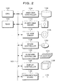
- Fig. 1 is a block diagram showing an embodiment of an information relevance display apparatus with a function structure thereof according to the invention.
- the information relevance display apparatus 10 is realized by a personal computer and, for example via the internet 12, is able to connect to databases 14-1, 14-2 and 14-3 of public sites, and to collect search target data from the databases 14-1 to 14-3 and execute a display process for information relevance.
- search target data collected from the databases 14-1 to 14-3 for example gene information published in the bioinformatics field may be quoted.
- the information relevance display apparatus 10 is provided with a search information management section 11, and to the search information management section 11, an element information file 16-1, an attribute information file 18-1, a relevance information file 20-1, an input device 22 such as a keyboard and a tablet and a display device 24 are connected.
- the search information management section 11 is provided with a search information input unit 26, a search designation unit 28, a relevance information extract (extraction) unit 30, a first network display process unit 32 and a second network display process unit 34, as functions to be achieved by execution of programs.
- the search information input unit 26 inputs the (downloaded) element information including element names and possessed attributes and stores it into the element information file 16-1, and simultaneously inputs the (downloaded) attribute information including attribute names and position information for an attribute hierarchical structure and stores it into the attribute information file 18-1.
- the search designation unit 28 designates plural pieces of the element information and the attribute information based on operations of the input device 22.
- the relevance information extract unit 30 extracts common attributes for two pieces of element information as relevance information from the possessed attributes of the plural pieces of the element information designated in the search designation unit 28, and stores these attributes into the relevance information file 20-1.
- the first network display process unit 32 arranges and displays the element information designated in the search designation unit 28 as the element nodes on the display screen of the display device 24, and also displays the first network in which each two element nodes having common attribute information are connected by an edge with reference to the relevance information in the relevance information file 20-1.
- the edge herein is a line with an orientation which defines one element node as a connection source and another element node as a connection destination, and in the following description, though this is defined as the edge, it represents a linear route which connects nodes in a network.
- the second network display process unit 34 converts and arranges the possessed attributes of the element nodes into the display of the attribute nodes in the first network displayed on the display device 24 by the first network display process unit 32, and displays the second network by connecting between the element nodes and the attribute nodes for the possessed attributes thereof with the edges.
- the second network display process unit 34 converts the edges into the attribute nodes by filtering the edges of the first network displayed by the first network display process unit 32, and performs the network display in which notable attributes are emphasized hereby.
- the personal computer which realises the information relevance display apparatus 10 in Fig. 1 is, for example, configured by hardware resources of a computer as shown in Fig. 2.
- a bus of CPU 100 is connected with RAM 102, a hard disk controller (software) 104, a floppy disk driver (software) 110, a CD-ROM driver (software) 114, a mouse controller 118, a keyboard controller 122, a display controller 126 and a communication board 130.
- the hard disk controller 104 is connected with a hard disk drive 106 and loaded with an application program which executes the information relevance display process of the invention, and by calling a necessary program from the hard disk drive 106 at startup of the computer, deploying the program in RAM 102 and executing it in CPU 100, the information relevance display by the display controller 126 is performed.
- the floppy disk driver 110 is connected with a floppy disk drive (hardware) 112 and can read from and write to a floppy disk (R).
- the CD-ROM driver 114 is connected with a CD drive (hardware) 116 and can read data and programs stored on a CD.
- the converted relevance information and network displays can be stored on the hard disk drive 106, and written to a floppy disk or CD or other medium.
- the mouse controller 118 transfers input operations with the mouse 120 to CPU 100.
- the keyboard controller 122 transfers input operations with the keyboard 124 to CPU 100.
- the display controller 126 performs the display on the display unit 128.
- the communication board 130 uses a communication line 132, collects information from the databases via networks such as the internet and communicates with other computers or servers.
- Fig. 3 is a block diagram of a display screen 36 of the information relevance which is displayed on the display device 24 by the first network display process unit 32 of Fig.1.
- this display screen 36 centering on a network display area 38, an element information list 42 is displayed on the underside, and an attribute information list 44 represented by a hierarchical directory structure is displayed on the left side, and an attribute appearance frequency list 45 is displayed under it.
- a filtering button 38-1 and a layout button 38-2 are provided at the upper left corner of the network display area 38; by manipulating the filtering button 38-1, the first network 40 as shown or the second network is displayed in the network display area 38 based on designations of search targets; and by manipulating the layout button 38-2, the element nodes and the attribute nodes are arranged depending on degrees of commonalities of the edges and weighting.
- This displayed information on the display screen 36 of the search information relevance display in Fig. 3 is based on element information 16 in Fig. 4, attribute information 18 in Fig. 5 and relevance information 20 in Fig. 6.
- the element information 16 in Fig. 4 consists of element ID 50, element names 52, possessed attributes 54 and element node display flags 55.
- the element information 16 is generated on the element information file 16-1 based on obtaining of search target data from the databases 14-1 to 14-3 by the search information input unit 26 provided to the search information management section 11 of Fig. 1.
- the attribute information 18 in Fig. 5 consists of attribute ID 56, attribute names 58, end flags 60, parent attributes 62, attribute information search flags 63 and attribute node display flags 64.
- the attribute information 18 when the attribute information 18 is represented using the attribute names 58, it has the hierarchical structure as shown in the attribute information list 44 in Fig. 3. This hierarchical structure is defined by the end flags 60 and the parent attributes 62.
- the attribute node display flags 64 are set to 1 in order to indicate attributes which are displayed as the attribute nodes in the second network.
- the relevance information 20 in Fig. 6 consists of relevance ID 65, connection source nodes 66 indicated by "From”, connection destination nodes 68 indicated by “To”, common attribute ID 70, edge display flags 72 and edge coupling strength 74.
- This relevance information 20 holds common attributes of two elements which are obtained by referring to the possessed attributes 54 of each of the elements in the element information 16 of Fig. 4, as the common attribute ID 70.
- the edge display flags 72 are set to 1 if the edge display is performed in the network display, and set to 0 if it's not performed.
- the set status of the edge display flags 72 in the relevance information 20 of Fig. 6 is the set status of the display flags for the display of the second network.
- the attribute node display is not performed and only the display of the element nodes is performed, therefore the inverse relevance occurs, wherein 0 in the edge display flag 72 will be 1 and 1 will be 0.
- the edge coupling strength 74 can be configured manually or automatically by calculations. In the automatic configuration by calculations, for example values corresponding to the number of the common attributes or the strength of the commonality are configured. This value of the edge coupling strength is utilized as the weight to correct the relevance in uniform arrangement of the element nodes in the first network.
- the first network 40 displayed in the network display area 38 on the display screen 36 of Fig. 3 is displayed based on the element information 16, the attribute information 18 and the relevance information 20 of Fig.4, Fig. 5 and Fig. 6, respectively.
- the element nodes 46-1, 46-2 and 46-3 are uniformly arranged, for example, in a circle shape.
- This arrangement of the element nodes 46-1 to 46-3 may be modified by using the values of the edge coupling strength 74 in the relevance information 20 as weights. For example, by checking the number of the common attribute IDs 70 in the relevance information 20, arrangement corresponding to this number of the common attribute IDs may be used.
- For the element nodes 46-1 to 46-3 arranged in the first network 40 "Node 1", “Node 2" and “Node 3" are displayed respectively, according to the element names 52 in the element information 16.
- the element nodes 46-1 to 46-3 in the arrangement display are connected with the edges 48-1, 48-2 and 48-3 based on the common attribute IDs 70 in the relevance information 20 in Fig. 6.
- the edge 48-1 represents the common attributes V003 and V005 which are possessed by the element nodes 46-1 and 46-2 herein.
- the edge 48-2 represents the common attributes V005 which are possessed by the element nodes 46-2 and 46-3.
- the edge 48-3 represents the common attributes V002 and V005 which are possessed by the element nodes 46-1 and 46-3.
- check boxes are provided to the element IDs and the attribute names respectively, and the element information and the attribute information to be the search targets are designated using these check boxes.
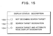
- the check box in the attribute information list 44 may indicate three different statuses 150, 152 and 154 as shown in Fig. 15.
- the display status 150 represents that the relevant attribute is not considered as the search target.
- the attributes which are not considered as the search target are displayed in neither the first network display nor the second network display. In this way, it is possible to limit the information displayed.
- the display status 154 represents that the relevant attribute is considered as the search target and also that it is displayed as the attribute node in the second network display.
- the network display area 38 will be converted to the display status of the second network 76 as shown in Fig. 7.
- the attribute names V11, V12 and V21 which express the edges 48-1, 48-2 and 48-3 in the first network 40 in Fig. 3 are designated as the attribute node display targets, as shown by the display status 154 in Fig. 15, by the check boxes of the attribute information list 44 in Fig.
- Fig. 8 illustrates distances L1, L2 and L3 which indicate the mutual positional relationship between the attribute nodes 78-1 to 78-3 in the second network 76.
- These distances L1, L2 and L3 which define the positional relations are based on the positional relevance in the hierarchical structure in the attribute information list 44 of Fig. 3, in which the attribute nodes 78-1 and 78-2 for the attribute names V11 and V12 are adjoining and this results in short distance L1.
- the attribute node 78-3 for the attribute name V21 is more distant from the attribute nodes 78-1 and 78-2 for the attribute names V11 and V12 in the hierarchical positions, it is arranged with distances L2 and L3 which are longer than the distance L1.
- the attribute nodes 78-1 to 78-3 which are arranged and represented in the second network 76 perform the edge representation for relations which are set to 1 in the edge display flags 72 in the relevance information 20 of Fig: 6, between the element nodes 46-1 to 46-3 already displayed in the network 40.
- the edges 80-1 to 80-7 are displayed as shown, from the attribute nodes 78-1 to 78-3 to the element nodes 46-1 to 46-3 which possess respective attributes.
- edges 80-1 to 80-7 From this display of edges 80-1 to 80-7, it is known that the attribute name V11 of the attribute node 78-1 is possessed by the element node 46-1 and the element node 46-3. Also, it is known that the attribute name V12 of the attribute node 78-2 is possessed by the element node 46-1 and the element node 46-2. Further, it is known that the attribute name V21 of the attribute node 78-3 is possessed by the element node 46-1, 46-2 and 46-3.
- Fig. 9 is the display of the second network 76-1 which is displayed, in the case that the edges of the first network 40 in Fig. 3 are displayed by the attribute nodes, when the V21 is removed from the attribute node display targets and the filtering button 38-1 is manipulated.
- the second network 76-1 is displayed with the attribute name V21 removed from the attribute node display targets, remaining attribute names V11 and V12 are displayed as the attribute nodes 78-1 and 78-2.
- the attribute node 78-3 of the attribute name V21 is represented by dotted lines for the purpose of easy-to-understand illustration, but actually, the attribute node 78-3 is not displayed.
- a second network in which all or some of the edges representing the common attributes between the element nodes in the first network 40 of Fig. 3 are designated as the attribute node display targets.
- the second network 76 and 76-1 in Fig.7 and Fig. 9 if the attribute names V11 and V12 are further removed from the attribute node display targets and the filtering button 38-1 in Fig. 3 is manipulated, then it is possible to go back to the former display of the first network 40.
- Fig. 10 is a flowchart of the information relevance display process according to an embodiment of the invention.
- the element information and the attribute information are input from the databases 14-1 to 14-3, and the element information 16 such as Fig. 4 and the attribute information 18 such as Fig. 5 are generated and stored in the element information file 16-1 and the attribute information file 18-1.
- the element information and the attribute information to be considered as the search targets are designated based on the operation of the input device by the user.
- step S3 considering plural pieces of designated element information as targets, common attribute information for two pieces of the element information is extracted, and the relevance information 20 such as Fig. 6 is generated and stored in the relevance information file 20-1.
- step S4 it is checked whether the designation for the first network display mode is present or not, and if present, the first network 40 is displayed in step S5, in which the element nodes are arranged and the edges are connected between two element nodes possessing common attributes, as shown by the first network 40 in Fig. 3. Also, in step S6, if the designation for the second network display mode is identified, then, for example as shown in Fig. 7, the second network 76 is displayed, in which the edges corresponding to the designated attributes in the first network are converted into the attribute nodes, arranged and displayed, and then the edges are connected between the element nodes and the attribute nodes for the possessed attributes thereof.
- the users perform display of the first network 40 as they change the designations for plural pieces of the element information and the attribute information to be considered as the search targets accordingly, convert the display into the second network display in which the edges in the first network 40 are converted into the attribute nodes and emphasized if necessary, and analyze characteristics of the search targets as they look at the network display.
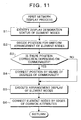
- Fig. 11 is a flowchart showing details of the first network display process in step S5 of Fig. 10.
- this first network display process after the display designation status of the elemental nodes is identified in step S1, uniform arrangement of the element nodes are determined in step S2. Subsequently, if position corrections are directed corresponding to the commonalities such as the number of the common attributes in step S3, the positions are corrected by means of the degrees of the commonalities in step S4.
- the arrangement control of the element nodes in step S4 for example the automatic arrangement of nodes in Japanese Patent No. 3350223 may be utilized. Subsequently, after arranging the element nodes, positions of which are determined in step S5, the edges for the common attributes are connected between the element nodes in step S6.
- Fig. 12 is a flowchart showing details of the second network display process in step S7 in Fig. 10.
- this second network display process after identifying display designation status of the element nodes and the attribute nodes in step S1, by referring to the relevance information 20 in Fig. 6, it is checked whether both of the connection source nodes 66 and the connection destination nodes 68 of the relevance information are in display designation or not in step S2.
- the element nodes display flags 55 in the element information 16 in Fig. 4 are referred for the display designation
- the attribute nodes display flags 64 in the attribute information 18 in Fig. 5 are referred to.
- step S3 it is checked whether the common attribute IDs are present or not. If the common attribute IDs are present, since these are (represent) relevance between the element nodes, determination for mixing the first network display is needed. On the other hand, if the common attribute IDs are not present, since it will be second network display, then proceed to step S6 and the edge display flags 72 is set to 1. If the common attribute IDs are present in step S3, it is checked whether all the common attribute IDs are displayed as the attribute nodes in step S4.
- step S5 If all the common attribute IDs are displayed as the attribute nodes, since the first network display is not necessary, then proceed to step S5 and the edge display flags are reset to 0. If there is the common attribute ID which is not displayed as the attribute node, since the first network display is mixed, then proceed to step S6 and the edge display flags are set to 1.
- step S7 it is checked whether the relevance IDs are identified in these steps S2 to S6 or not for all the relevance IDs 65, which is R001 to R011 in this case, in the relevance information 20 of Fig. 6, and if identified, proceed to step S8.
- step S8 the edges for the designated attributes in the first network are converted into the attribute nodes, and the converted attribute nodes are arranged with distances corresponding to the positions in the attribute hierarchical structure.
- step S9 the edges for which the edge display flags 72 are set to 1 as shown in the relevance information 20 of Fig. 6 are displayed between the attribute nodes and the element nodes.
- Fig. 13 is a schematic diagram of a display screen of the first network in the case that the invention is applied to the relevance display of gene information.
- a first network 86 is displayed in a network display area 84.
- gene information is displayed as an element information list 88.
- an attribute information list 90 is displayed, and attributes are provided with check boxes to designate as targets.
- the element information list 88 is provided with check boxes on the left of each gene as well.
- an attribute appearance frequency list 92 is provided in the upper left of the network display area 84.
- a filtering button 136 and a layout button 148 are provided in the upper left of the network display area 84.
- the filtering button 136 is manipulated, it is converted to a display screen of a second network 94 shown in Fig. 14, for example.
- the attribute nodes designated as the attribute node display targets are connected to the element nodes possessing the attributes thereof by the edges.
- the display process of information relevance targeting gene information is taken as an example, the invention is not limited to this and can be directly applied to analysis targeting information in which attribute information is added to appropriate element information, for example the analysis of personal purchasing information obtained as POS information in convenience stores, the analysis of patent information and the like.
- the invention includes any alteration not impairing the purpose and the benefit thereof and also is not limited by the numeric values shown in the above embodiments.
- nodes at which the edges are concentrated can be comprehended as the nodes with high commonality at a glance and can be comprehended as notable elements.
- attribute nodes in the second network in which the edges in the first network are converted into the attribute nodes by performing arrangement of the attribute nodes based on a hierarchical structure or appearance frequencies of attributes, it is facilitated to narrow down attributes or attribute groups of interest, and the discovery of new knowledge is promoted.
- the present invention provides a data processing technique in the form of an information relevance display method, program, storage medium and apparatus which analyze, display and record the relevance in a network of elements which are connected as nodes by edges of common attributes.
Landscapes
- Engineering & Computer Science (AREA)
- Databases & Information Systems (AREA)
- Theoretical Computer Science (AREA)
- Computational Linguistics (AREA)
- Data Mining & Analysis (AREA)
- Physics & Mathematics (AREA)
- General Engineering & Computer Science (AREA)
- General Physics & Mathematics (AREA)
- Information Retrieval, Db Structures And Fs Structures Therefor (AREA)
- User Interface Of Digital Computer (AREA)
- Information Transfer Between Computers (AREA)
Applications Claiming Priority (2)
| Application Number | Priority Date | Filing Date | Title |
|---|---|---|---|
| JP2003055312 | 2003-03-03 | ||
| JP2003055312A JP4199026B2 (ja) | 2003-03-03 | 2003-03-03 | 情報関連性表示方法、プログラム、記憶媒体及び装置 |
Publications (2)
| Publication Number | Publication Date |
|---|---|
| EP1455283A2 true EP1455283A2 (de) | 2004-09-08 |
| EP1455283A3 EP1455283A3 (de) | 2006-04-12 |
Family
ID=32821138
Family Applications (1)
| Application Number | Title | Priority Date | Filing Date |
|---|---|---|---|
| EP04250630A Withdrawn EP1455283A3 (de) | 2003-03-03 | 2004-02-05 | Verfahren, Speichermedium und Vorrichtung für Darstellung von relevanten Informationen |
Country Status (5)
| Country | Link |
|---|---|
| US (1) | US7203698B2 (de) |
| EP (1) | EP1455283A3 (de) |
| JP (1) | JP4199026B2 (de) |
| CN (1) | CN100573509C (de) |
| AU (1) | AU2004200402A1 (de) |
Families Citing this family (26)
| Publication number | Priority date | Publication date | Assignee | Title |
|---|---|---|---|---|
| US6944830B2 (en) * | 2000-12-21 | 2005-09-13 | Xerox Corporation | System and method for browsing hierarchically based node-link structures based on an estimated degree of interest |
| US7672950B2 (en) * | 2004-05-04 | 2010-03-02 | The Boston Consulting Group, Inc. | Method and apparatus for selecting, analyzing, and visualizing related database records as a network |
| WO2007095997A1 (de) * | 2006-02-23 | 2007-08-30 | Netbreeze Gmbh | System und verfahren zur benutzergesteuerten multidimensionalen navigation und/oder themenbasierten aggregation und/oder überwachung von multimediadaten |
| US7774288B2 (en) * | 2006-05-16 | 2010-08-10 | Sony Corporation | Clustering and classification of multimedia data |
| US20070271286A1 (en) * | 2006-05-16 | 2007-11-22 | Khemdut Purang | Dimensionality reduction for content category data |
| US7840568B2 (en) * | 2006-05-16 | 2010-11-23 | Sony Corporation | Sorting media objects by similarity |
| US9330170B2 (en) * | 2006-05-16 | 2016-05-03 | Sony Corporation | Relating objects in different mediums |
| US20070271274A1 (en) * | 2006-05-16 | 2007-11-22 | Khemdut Purang | Using a community generated web site for metadata |
| US7750909B2 (en) * | 2006-05-16 | 2010-07-06 | Sony Corporation | Ordering artists by overall degree of influence |
| US7961189B2 (en) * | 2006-05-16 | 2011-06-14 | Sony Corporation | Displaying artists related to an artist of interest |
| JP5154975B2 (ja) * | 2008-02-26 | 2013-02-27 | 日本電信電話株式会社 | 興味体系グラフ形成装置、興味体系グラフ形成方法、および、興味体系グラフ形成プログラム |
| US20090248716A1 (en) * | 2008-03-31 | 2009-10-01 | Caterpillar Inc. | Hierarchy creation and management tool |
| US20100070593A1 (en) * | 2008-09-18 | 2010-03-18 | Craig Peter Sayers | Visualizing features of messages communicated between users |
| US20110296325A1 (en) * | 2010-06-01 | 2011-12-01 | Sony Corporation | Method and apparatus for user interface display |
| US8775955B2 (en) * | 2010-12-02 | 2014-07-08 | Sap Ag | Attraction-based data visualization |
| US9720930B2 (en) * | 2012-01-30 | 2017-08-01 | Accenture Global Services Limited | Travel management |
| CN102831217B (zh) * | 2012-08-17 | 2015-03-04 | 安科智慧城市技术(中国)有限公司 | 一种数据处理方法及装置 |
| CN103019691B (zh) * | 2012-11-20 | 2016-08-10 | 北京思特奇信息技术股份有限公司 | 一种etl作业关系图的转化方法及其实现系统 |
| JP6110139B2 (ja) * | 2012-12-28 | 2017-04-05 | 富士通株式会社 | ファイル管理プログラム、ファイル管理装置およびファイル管理方法 |
| JP6107419B2 (ja) * | 2013-05-23 | 2017-04-05 | 富士通株式会社 | 表示制御方法、表示制御プログラムおよび表示制御装置 |
| CN103729441B (zh) * | 2013-12-30 | 2017-10-24 | 优视科技有限公司 | 媒体对象展示方法及装置 |
| US10528522B1 (en) | 2016-03-17 | 2020-01-07 | EMC IP Holding Company LLC | Metadata-based data valuation |
| CN109643578B (zh) * | 2016-06-01 | 2023-07-21 | 生命科技股份有限公司 | 用于设计基因组合的方法和系统 |
| CN107133197B (zh) * | 2017-04-20 | 2020-09-15 | 东莞中国科学院云计算产业技术创新与育成中心 | 多重数据展示方法和装置 |
| US11023481B2 (en) * | 2018-08-08 | 2021-06-01 | commos inc. | Navigation platform for performing search queries |
| JP7718298B2 (ja) * | 2022-03-10 | 2025-08-05 | 富士通株式会社 | 情報処理プログラム,情報処理方法及び情報処理装置 |
Family Cites Families (5)
| Publication number | Priority date | Publication date | Assignee | Title |
|---|---|---|---|---|
| JP3350223B2 (ja) * | 1994-07-13 | 2002-11-25 | 富士通株式会社 | グラフ自動レイアウト方法及び装置 |
| AU3109200A (en) * | 1998-12-04 | 2000-06-26 | Technology Enabling Company, Llc | Systems and methods for organizing data |
| AU7110500A (en) * | 1999-09-02 | 2001-03-26 | Children's Medical Center Corporation | A system and method for mining data from a database using relevance networks |
| WO2002011048A2 (en) * | 2000-07-31 | 2002-02-07 | Agilix Corporation | Visualization and manipulation of biomolecular relationships using graph operators |
| JP2002091991A (ja) * | 2000-09-20 | 2002-03-29 | Intec Web & Genome Informatics Corp | 遺伝子ネットワーク研究支援システム及び方法 |
-
2003
- 2003-03-03 JP JP2003055312A patent/JP4199026B2/ja not_active Expired - Fee Related
-
2004
- 2004-01-19 CN CNB2004100027284A patent/CN100573509C/zh not_active Expired - Fee Related
- 2004-02-04 AU AU2004200402A patent/AU2004200402A1/en not_active Abandoned
- 2004-02-05 EP EP04250630A patent/EP1455283A3/de not_active Withdrawn
- 2004-02-06 US US10/772,298 patent/US7203698B2/en not_active Expired - Fee Related
Also Published As
| Publication number | Publication date |
|---|---|
| US7203698B2 (en) | 2007-04-10 |
| JP2004265179A (ja) | 2004-09-24 |
| CN1527225A (zh) | 2004-09-08 |
| CN100573509C (zh) | 2009-12-23 |
| AU2004200402A1 (en) | 2004-09-23 |
| JP4199026B2 (ja) | 2008-12-17 |
| US20040193587A1 (en) | 2004-09-30 |
| EP1455283A3 (de) | 2006-04-12 |
Similar Documents
| Publication | Publication Date | Title |
|---|---|---|
| EP1455283A2 (de) | Verfahren, Speichermedium und Vorrichtung für Darstellung von relevanten Informationen | |
| US6718336B1 (en) | Data import system for data analysis system | |
| US8766980B2 (en) | Information management system, method and program | |
| US20100114355A1 (en) | Method and system for management of manufacturing information | |
| WO2002011048A2 (en) | Visualization and manipulation of biomolecular relationships using graph operators | |
| JP2001325103A (ja) | シミュレータ作成方法、シミュレータ作成装置およびシミュレータの作成支援方法 | |
| Ioannakis et al. | RETRIEVAL—an online performance evaluation tool for information retrieval methods | |
| US20080059437A1 (en) | Data mining system | |
| CN113377765A (zh) | 一种多组学数据分析系统及其数据转换方法 | |
| JPS6250931A (ja) | パラメ−タ・テ−ブルの利用方式 | |
| WO2004055709A2 (en) | Methods for identifying, viewing, and analyzing syntenic and orthologous genomic regions between two or more species | |
| Paton | Managing and sharing experimental data: standards, tools and pitfalls | |
| JP2012037936A (ja) | 文書分析装置およびプログラム | |
| JP3563315B2 (ja) | 樹状図表示方法及び樹状図表示システム | |
| JP2007304796A (ja) | データベース解析システム及びデータベース解析方法及びプログラム | |
| JP2000276338A (ja) | 視覚プログラミング方法およびシステムならびに視覚プログラミングのための記録媒体 | |
| JP2005190212A (ja) | データベースシステム、データ処理方法及びプログラム | |
| JP2001142885A (ja) | 業務名指定による問合せsql生成装置 | |
| WO2013080657A1 (ja) | 製品情報管理装置、方法、及びプログラム | |
| JP2008135057A (ja) | 検索処理方法及びプログラム | |
| JP4076415B2 (ja) | 検索方法、検索装置、及びコンピュータプログラム | |
| KR20210156683A (ko) | 빅데이터 시각화 시스템 및 방법 | |
| Myers et al. | Multivariate methods of representing relations in R for prioritization purposes: selective scaling, comparative clustering, collective criteria and sequenced sets | |
| Charte et al. | Working with multilabel datasets in r: The mldr package | |
| Luiza et al. | New approach to genomics experiments taking advantage of virtual laboratory system |
Legal Events
| Date | Code | Title | Description |
|---|---|---|---|
| PUAI | Public reference made under article 153(3) epc to a published international application that has entered the european phase |
Free format text: ORIGINAL CODE: 0009012 |
|
| AK | Designated contracting states |
Kind code of ref document: A2 Designated state(s): AT BE BG CH CY CZ DE DK EE ES FI FR GB GR HU IE IT LI LU MC NL PT RO SE SI SK TR |
|
| AX | Request for extension of the european patent |
Extension state: AL LT LV MK |
|
| PUAL | Search report despatched |
Free format text: ORIGINAL CODE: 0009013 |
|
| AK | Designated contracting states |
Kind code of ref document: A3 Designated state(s): AT BE BG CH CY CZ DE DK EE ES FI FR GB GR HU IE IT LI LU MC NL PT RO SE SI SK TR |
|
| AX | Request for extension of the european patent |
Extension state: AL LT LV MK |
|
| RIC1 | Information provided on ipc code assigned before grant |
Ipc: G06F 19/00 20060101ALI20060221BHEP Ipc: G06F 17/30 20060101AFI20040713BHEP |
|
| 17P | Request for examination filed |
Effective date: 20061009 |
|
| AKX | Designation fees paid |
Designated state(s): DE GB |
|
| 17Q | First examination report despatched |
Effective date: 20070508 |
|
| STAA | Information on the status of an ep patent application or granted ep patent |
Free format text: STATUS: THE APPLICATION IS DEEMED TO BE WITHDRAWN |
|
| 18D | Application deemed to be withdrawn |
Effective date: 20070919 |