EP1456048B1 - A transmission system with a continuously variable transmission ratio - Google Patents
A transmission system with a continuously variable transmission ratio Download PDFInfo
- Publication number
- EP1456048B1 EP1456048B1 EP02796610A EP02796610A EP1456048B1 EP 1456048 B1 EP1456048 B1 EP 1456048B1 EP 02796610 A EP02796610 A EP 02796610A EP 02796610 A EP02796610 A EP 02796610A EP 1456048 B1 EP1456048 B1 EP 1456048B1
- Authority
- EP
- European Patent Office
- Prior art keywords
- rotor
- ice
- cvt
- torque
- winding
- Prior art date
- Legal status (The legal status is an assumption and is not a legal conclusion. Google has not performed a legal analysis and makes no representation as to the accuracy of the status listed.)
- Expired - Lifetime
Links
Images






Classifications
-
- B—PERFORMING OPERATIONS; TRANSPORTING
- B60—VEHICLES IN GENERAL
- B60K—ARRANGEMENT OR MOUNTING OF PROPULSION UNITS OR OF TRANSMISSIONS IN VEHICLES; ARRANGEMENT OR MOUNTING OF PLURAL DIVERSE PRIME-MOVERS IN VEHICLES; AUXILIARY DRIVES FOR VEHICLES; INSTRUMENTATION OR DASHBOARDS FOR VEHICLES; ARRANGEMENTS IN CONNECTION WITH COOLING, AIR INTAKE, GAS EXHAUST OR FUEL SUPPLY OF PROPULSION UNITS IN VEHICLES
- B60K6/00—Arrangement or mounting of plural diverse prime-movers for mutual or common propulsion, e.g. hybrid propulsion systems comprising electric motors and internal combustion engines
- B60K6/20—Arrangement or mounting of plural diverse prime-movers for mutual or common propulsion, e.g. hybrid propulsion systems comprising electric motors and internal combustion engines the prime-movers consisting of electric motors and internal combustion engines, e.g. HEVs
- B60K6/42—Arrangement or mounting of plural diverse prime-movers for mutual or common propulsion, e.g. hybrid propulsion systems comprising electric motors and internal combustion engines the prime-movers consisting of electric motors and internal combustion engines, e.g. HEVs characterised by the architecture of the hybrid electric vehicle
- B60K6/44—Series-parallel type
- B60K6/448—Electrical distribution type
-
- B—PERFORMING OPERATIONS; TRANSPORTING
- B60—VEHICLES IN GENERAL
- B60L—PROPULSION OF ELECTRICALLY-PROPELLED VEHICLES; SUPPLYING ELECTRIC POWER FOR AUXILIARY EQUIPMENT OF ELECTRICALLY-PROPELLED VEHICLES; ELECTRODYNAMIC BRAKE SYSTEMS FOR VEHICLES IN GENERAL; MAGNETIC SUSPENSION OR LEVITATION FOR VEHICLES; MONITORING OPERATING VARIABLES OF ELECTRICALLY-PROPELLED VEHICLES; ELECTRIC SAFETY DEVICES FOR ELECTRICALLY-PROPELLED VEHICLES
- B60L15/00—Methods, circuits, or devices for controlling the traction-motor speed of electrically-propelled vehicles
- B60L15/20—Methods, circuits, or devices for controlling the traction-motor speed of electrically-propelled vehicles for control of the vehicle or its driving motor to achieve a desired performance, e.g. speed, torque, programmed variation of speed
- B60L15/2072—Methods, circuits, or devices for controlling the traction-motor speed of electrically-propelled vehicles for control of the vehicle or its driving motor to achieve a desired performance, e.g. speed, torque, programmed variation of speed for drive off
-
- B—PERFORMING OPERATIONS; TRANSPORTING
- B60—VEHICLES IN GENERAL
- B60L—PROPULSION OF ELECTRICALLY-PROPELLED VEHICLES; SUPPLYING ELECTRIC POWER FOR AUXILIARY EQUIPMENT OF ELECTRICALLY-PROPELLED VEHICLES; ELECTRODYNAMIC BRAKE SYSTEMS FOR VEHICLES IN GENERAL; MAGNETIC SUSPENSION OR LEVITATION FOR VEHICLES; MONITORING OPERATING VARIABLES OF ELECTRICALLY-PROPELLED VEHICLES; ELECTRIC SAFETY DEVICES FOR ELECTRICALLY-PROPELLED VEHICLES
- B60L15/00—Methods, circuits, or devices for controlling the traction-motor speed of electrically-propelled vehicles
- B60L15/20—Methods, circuits, or devices for controlling the traction-motor speed of electrically-propelled vehicles for control of the vehicle or its driving motor to achieve a desired performance, e.g. speed, torque, programmed variation of speed
- B60L15/2072—Methods, circuits, or devices for controlling the traction-motor speed of electrically-propelled vehicles for control of the vehicle or its driving motor to achieve a desired performance, e.g. speed, torque, programmed variation of speed for drive off
- B60L15/2081—Methods, circuits, or devices for controlling the traction-motor speed of electrically-propelled vehicles for control of the vehicle or its driving motor to achieve a desired performance, e.g. speed, torque, programmed variation of speed for drive off for drive off on a slope
-
- B—PERFORMING OPERATIONS; TRANSPORTING
- B60—VEHICLES IN GENERAL
- B60L—PROPULSION OF ELECTRICALLY-PROPELLED VEHICLES; SUPPLYING ELECTRIC POWER FOR AUXILIARY EQUIPMENT OF ELECTRICALLY-PROPELLED VEHICLES; ELECTRODYNAMIC BRAKE SYSTEMS FOR VEHICLES IN GENERAL; MAGNETIC SUSPENSION OR LEVITATION FOR VEHICLES; MONITORING OPERATING VARIABLES OF ELECTRICALLY-PROPELLED VEHICLES; ELECTRIC SAFETY DEVICES FOR ELECTRICALLY-PROPELLED VEHICLES
- B60L50/00—Electric propulsion with power supplied within the vehicle
- B60L50/10—Electric propulsion with power supplied within the vehicle using propulsion power supplied by engine-driven generators, e.g. generators driven by combustion engines
- B60L50/16—Electric propulsion with power supplied within the vehicle using propulsion power supplied by engine-driven generators, e.g. generators driven by combustion engines with provision for separate direct mechanical propulsion
-
- B—PERFORMING OPERATIONS; TRANSPORTING
- B60—VEHICLES IN GENERAL
- B60L—PROPULSION OF ELECTRICALLY-PROPELLED VEHICLES; SUPPLYING ELECTRIC POWER FOR AUXILIARY EQUIPMENT OF ELECTRICALLY-PROPELLED VEHICLES; ELECTRODYNAMIC BRAKE SYSTEMS FOR VEHICLES IN GENERAL; MAGNETIC SUSPENSION OR LEVITATION FOR VEHICLES; MONITORING OPERATING VARIABLES OF ELECTRICALLY-PROPELLED VEHICLES; ELECTRIC SAFETY DEVICES FOR ELECTRICALLY-PROPELLED VEHICLES
- B60L50/00—Electric propulsion with power supplied within the vehicle
- B60L50/50—Electric propulsion with power supplied within the vehicle using propulsion power supplied by batteries or fuel cells
- B60L50/60—Electric propulsion with power supplied within the vehicle using propulsion power supplied by batteries or fuel cells using power supplied by batteries
- B60L50/61—Electric propulsion with power supplied within the vehicle using propulsion power supplied by batteries or fuel cells using power supplied by batteries by batteries charged by engine-driven generators, e.g. series hybrid electric vehicles
-
- B—PERFORMING OPERATIONS; TRANSPORTING
- B60—VEHICLES IN GENERAL
- B60W—CONJOINT CONTROL OF VEHICLE SUB-UNITS OF DIFFERENT TYPE OR DIFFERENT FUNCTION; CONTROL SYSTEMS SPECIALLY ADAPTED FOR HYBRID VEHICLES; ROAD VEHICLE DRIVE CONTROL SYSTEMS FOR PURPOSES NOT RELATED TO THE CONTROL OF A PARTICULAR SUB-UNIT
- B60W10/00—Conjoint control of vehicle sub-units of different type or different function
- B60W10/04—Conjoint control of vehicle sub-units of different type or different function including control of propulsion units
- B60W10/08—Conjoint control of vehicle sub-units of different type or different function including control of propulsion units including control of electric propulsion units, e.g. motors or generators
-
- F—MECHANICAL ENGINEERING; LIGHTING; HEATING; WEAPONS; BLASTING
- F02—COMBUSTION ENGINES; HOT-GAS OR COMBUSTION-PRODUCT ENGINE PLANTS
- F02N—STARTING OF COMBUSTION ENGINES; STARTING AIDS FOR SUCH ENGINES, NOT OTHERWISE PROVIDED FOR
- F02N11/00—Starting of engines by means of electric motors
- F02N11/04—Starting of engines by means of electric motors the motors being associated with current generators
-
- H—ELECTRICITY
- H02—GENERATION; CONVERSION OR DISTRIBUTION OF ELECTRIC POWER
- H02K—DYNAMO-ELECTRIC MACHINES
- H02K16/00—Machines with more than one rotor or stator
- H02K16/02—Machines with one stator and two or more rotors
-
- H—ELECTRICITY
- H02—GENERATION; CONVERSION OR DISTRIBUTION OF ELECTRIC POWER
- H02K—DYNAMO-ELECTRIC MACHINES
- H02K51/00—Dynamo-electric gears, i.e. dynamo-electric means for transmitting mechanical power from a driving shaft to a driven shaft and comprising structurally interrelated motor and generator parts
-
- B—PERFORMING OPERATIONS; TRANSPORTING
- B60—VEHICLES IN GENERAL
- B60K—ARRANGEMENT OR MOUNTING OF PROPULSION UNITS OR OF TRANSMISSIONS IN VEHICLES; ARRANGEMENT OR MOUNTING OF PLURAL DIVERSE PRIME-MOVERS IN VEHICLES; AUXILIARY DRIVES FOR VEHICLES; INSTRUMENTATION OR DASHBOARDS FOR VEHICLES; ARRANGEMENTS IN CONNECTION WITH COOLING, AIR INTAKE, GAS EXHAUST OR FUEL SUPPLY OF PROPULSION UNITS IN VEHICLES
- B60K6/00—Arrangement or mounting of plural diverse prime-movers for mutual or common propulsion, e.g. hybrid propulsion systems comprising electric motors and internal combustion engines
- B60K6/20—Arrangement or mounting of plural diverse prime-movers for mutual or common propulsion, e.g. hybrid propulsion systems comprising electric motors and internal combustion engines the prime-movers consisting of electric motors and internal combustion engines, e.g. HEVs
- B60K6/22—Arrangement or mounting of plural diverse prime-movers for mutual or common propulsion, e.g. hybrid propulsion systems comprising electric motors and internal combustion engines the prime-movers consisting of electric motors and internal combustion engines, e.g. HEVs characterised by apparatus, components or means specially adapted for HEVs
- B60K6/26—Arrangement or mounting of plural diverse prime-movers for mutual or common propulsion, e.g. hybrid propulsion systems comprising electric motors and internal combustion engines the prime-movers consisting of electric motors and internal combustion engines, e.g. HEVs characterised by apparatus, components or means specially adapted for HEVs characterised by the motors or the generators
- B60K2006/262—Arrangement or mounting of plural diverse prime-movers for mutual or common propulsion, e.g. hybrid propulsion systems comprising electric motors and internal combustion engines the prime-movers consisting of electric motors and internal combustion engines, e.g. HEVs characterised by apparatus, components or means specially adapted for HEVs characterised by the motors or the generators the motor or generator are used as clutch, e.g. between engine and driveshaft
-
- B—PERFORMING OPERATIONS; TRANSPORTING
- B60—VEHICLES IN GENERAL
- B60K—ARRANGEMENT OR MOUNTING OF PROPULSION UNITS OR OF TRANSMISSIONS IN VEHICLES; ARRANGEMENT OR MOUNTING OF PLURAL DIVERSE PRIME-MOVERS IN VEHICLES; AUXILIARY DRIVES FOR VEHICLES; INSTRUMENTATION OR DASHBOARDS FOR VEHICLES; ARRANGEMENTS IN CONNECTION WITH COOLING, AIR INTAKE, GAS EXHAUST OR FUEL SUPPLY OF PROPULSION UNITS IN VEHICLES
- B60K6/00—Arrangement or mounting of plural diverse prime-movers for mutual or common propulsion, e.g. hybrid propulsion systems comprising electric motors and internal combustion engines
- B60K6/20—Arrangement or mounting of plural diverse prime-movers for mutual or common propulsion, e.g. hybrid propulsion systems comprising electric motors and internal combustion engines the prime-movers consisting of electric motors and internal combustion engines, e.g. HEVs
- B60K6/22—Arrangement or mounting of plural diverse prime-movers for mutual or common propulsion, e.g. hybrid propulsion systems comprising electric motors and internal combustion engines the prime-movers consisting of electric motors and internal combustion engines, e.g. HEVs characterised by apparatus, components or means specially adapted for HEVs
- B60K6/26—Arrangement or mounting of plural diverse prime-movers for mutual or common propulsion, e.g. hybrid propulsion systems comprising electric motors and internal combustion engines the prime-movers consisting of electric motors and internal combustion engines, e.g. HEVs characterised by apparatus, components or means specially adapted for HEVs characterised by the motors or the generators
- B60K2006/268—Electric drive motor starts the engine, i.e. used as starter motor
-
- B—PERFORMING OPERATIONS; TRANSPORTING
- B60—VEHICLES IN GENERAL
- B60L—PROPULSION OF ELECTRICALLY-PROPELLED VEHICLES; SUPPLYING ELECTRIC POWER FOR AUXILIARY EQUIPMENT OF ELECTRICALLY-PROPELLED VEHICLES; ELECTRODYNAMIC BRAKE SYSTEMS FOR VEHICLES IN GENERAL; MAGNETIC SUSPENSION OR LEVITATION FOR VEHICLES; MONITORING OPERATING VARIABLES OF ELECTRICALLY-PROPELLED VEHICLES; ELECTRIC SAFETY DEVICES FOR ELECTRICALLY-PROPELLED VEHICLES
- B60L2240/00—Control parameters of input or output; Target parameters
- B60L2240/10—Vehicle control parameters
- B60L2240/12—Speed
-
- B—PERFORMING OPERATIONS; TRANSPORTING
- B60—VEHICLES IN GENERAL
- B60L—PROPULSION OF ELECTRICALLY-PROPELLED VEHICLES; SUPPLYING ELECTRIC POWER FOR AUXILIARY EQUIPMENT OF ELECTRICALLY-PROPELLED VEHICLES; ELECTRODYNAMIC BRAKE SYSTEMS FOR VEHICLES IN GENERAL; MAGNETIC SUSPENSION OR LEVITATION FOR VEHICLES; MONITORING OPERATING VARIABLES OF ELECTRICALLY-PROPELLED VEHICLES; ELECTRIC SAFETY DEVICES FOR ELECTRICALLY-PROPELLED VEHICLES
- B60L2240/00—Control parameters of input or output; Target parameters
- B60L2240/10—Vehicle control parameters
- B60L2240/32—Driving direction
-
- B—PERFORMING OPERATIONS; TRANSPORTING
- B60—VEHICLES IN GENERAL
- B60L—PROPULSION OF ELECTRICALLY-PROPELLED VEHICLES; SUPPLYING ELECTRIC POWER FOR AUXILIARY EQUIPMENT OF ELECTRICALLY-PROPELLED VEHICLES; ELECTRODYNAMIC BRAKE SYSTEMS FOR VEHICLES IN GENERAL; MAGNETIC SUSPENSION OR LEVITATION FOR VEHICLES; MONITORING OPERATING VARIABLES OF ELECTRICALLY-PROPELLED VEHICLES; ELECTRIC SAFETY DEVICES FOR ELECTRICALLY-PROPELLED VEHICLES
- B60L2240/00—Control parameters of input or output; Target parameters
- B60L2240/40—Drive Train control parameters
- B60L2240/42—Drive Train control parameters related to electric machines
- B60L2240/421—Speed
-
- B—PERFORMING OPERATIONS; TRANSPORTING
- B60—VEHICLES IN GENERAL
- B60L—PROPULSION OF ELECTRICALLY-PROPELLED VEHICLES; SUPPLYING ELECTRIC POWER FOR AUXILIARY EQUIPMENT OF ELECTRICALLY-PROPELLED VEHICLES; ELECTRODYNAMIC BRAKE SYSTEMS FOR VEHICLES IN GENERAL; MAGNETIC SUSPENSION OR LEVITATION FOR VEHICLES; MONITORING OPERATING VARIABLES OF ELECTRICALLY-PROPELLED VEHICLES; ELECTRIC SAFETY DEVICES FOR ELECTRICALLY-PROPELLED VEHICLES
- B60L2240/00—Control parameters of input or output; Target parameters
- B60L2240/40—Drive Train control parameters
- B60L2240/42—Drive Train control parameters related to electric machines
- B60L2240/423—Torque
-
- B—PERFORMING OPERATIONS; TRANSPORTING
- B60—VEHICLES IN GENERAL
- B60L—PROPULSION OF ELECTRICALLY-PROPELLED VEHICLES; SUPPLYING ELECTRIC POWER FOR AUXILIARY EQUIPMENT OF ELECTRICALLY-PROPELLED VEHICLES; ELECTRODYNAMIC BRAKE SYSTEMS FOR VEHICLES IN GENERAL; MAGNETIC SUSPENSION OR LEVITATION FOR VEHICLES; MONITORING OPERATING VARIABLES OF ELECTRICALLY-PROPELLED VEHICLES; ELECTRIC SAFETY DEVICES FOR ELECTRICALLY-PROPELLED VEHICLES
- B60L2240/00—Control parameters of input or output; Target parameters
- B60L2240/60—Navigation input
- B60L2240/64—Road conditions
- B60L2240/642—Slope of road
-
- B—PERFORMING OPERATIONS; TRANSPORTING
- B60—VEHICLES IN GENERAL
- B60L—PROPULSION OF ELECTRICALLY-PROPELLED VEHICLES; SUPPLYING ELECTRIC POWER FOR AUXILIARY EQUIPMENT OF ELECTRICALLY-PROPELLED VEHICLES; ELECTRODYNAMIC BRAKE SYSTEMS FOR VEHICLES IN GENERAL; MAGNETIC SUSPENSION OR LEVITATION FOR VEHICLES; MONITORING OPERATING VARIABLES OF ELECTRICALLY-PROPELLED VEHICLES; ELECTRIC SAFETY DEVICES FOR ELECTRICALLY-PROPELLED VEHICLES
- B60L2240/00—Control parameters of input or output; Target parameters
- B60L2240/80—Time limits
-
- B—PERFORMING OPERATIONS; TRANSPORTING
- B60—VEHICLES IN GENERAL
- B60L—PROPULSION OF ELECTRICALLY-PROPELLED VEHICLES; SUPPLYING ELECTRIC POWER FOR AUXILIARY EQUIPMENT OF ELECTRICALLY-PROPELLED VEHICLES; ELECTRODYNAMIC BRAKE SYSTEMS FOR VEHICLES IN GENERAL; MAGNETIC SUSPENSION OR LEVITATION FOR VEHICLES; MONITORING OPERATING VARIABLES OF ELECTRICALLY-PROPELLED VEHICLES; ELECTRIC SAFETY DEVICES FOR ELECTRICALLY-PROPELLED VEHICLES
- B60L2260/00—Operating Modes
- B60L2260/20—Drive modes; Transition between modes
- B60L2260/28—Four wheel or all wheel drive
-
- Y—GENERAL TAGGING OF NEW TECHNOLOGICAL DEVELOPMENTS; GENERAL TAGGING OF CROSS-SECTIONAL TECHNOLOGIES SPANNING OVER SEVERAL SECTIONS OF THE IPC; TECHNICAL SUBJECTS COVERED BY FORMER USPC CROSS-REFERENCE ART COLLECTIONS [XRACs] AND DIGESTS
- Y02—TECHNOLOGIES OR APPLICATIONS FOR MITIGATION OR ADAPTATION AGAINST CLIMATE CHANGE
- Y02T—CLIMATE CHANGE MITIGATION TECHNOLOGIES RELATED TO TRANSPORTATION
- Y02T10/00—Road transport of goods or passengers
- Y02T10/60—Other road transportation technologies with climate change mitigation effect
- Y02T10/62—Hybrid vehicles
-
- Y—GENERAL TAGGING OF NEW TECHNOLOGICAL DEVELOPMENTS; GENERAL TAGGING OF CROSS-SECTIONAL TECHNOLOGIES SPANNING OVER SEVERAL SECTIONS OF THE IPC; TECHNICAL SUBJECTS COVERED BY FORMER USPC CROSS-REFERENCE ART COLLECTIONS [XRACs] AND DIGESTS
- Y02—TECHNOLOGIES OR APPLICATIONS FOR MITIGATION OR ADAPTATION AGAINST CLIMATE CHANGE
- Y02T—CLIMATE CHANGE MITIGATION TECHNOLOGIES RELATED TO TRANSPORTATION
- Y02T10/00—Road transport of goods or passengers
- Y02T10/60—Other road transportation technologies with climate change mitigation effect
- Y02T10/64—Electric machine technologies in electromobility
-
- Y—GENERAL TAGGING OF NEW TECHNOLOGICAL DEVELOPMENTS; GENERAL TAGGING OF CROSS-SECTIONAL TECHNOLOGIES SPANNING OVER SEVERAL SECTIONS OF THE IPC; TECHNICAL SUBJECTS COVERED BY FORMER USPC CROSS-REFERENCE ART COLLECTIONS [XRACs] AND DIGESTS
- Y02—TECHNOLOGIES OR APPLICATIONS FOR MITIGATION OR ADAPTATION AGAINST CLIMATE CHANGE
- Y02T—CLIMATE CHANGE MITIGATION TECHNOLOGIES RELATED TO TRANSPORTATION
- Y02T10/00—Road transport of goods or passengers
- Y02T10/60—Other road transportation technologies with climate change mitigation effect
- Y02T10/70—Energy storage systems for electromobility, e.g. batteries
-
- Y—GENERAL TAGGING OF NEW TECHNOLOGICAL DEVELOPMENTS; GENERAL TAGGING OF CROSS-SECTIONAL TECHNOLOGIES SPANNING OVER SEVERAL SECTIONS OF THE IPC; TECHNICAL SUBJECTS COVERED BY FORMER USPC CROSS-REFERENCE ART COLLECTIONS [XRACs] AND DIGESTS
- Y02—TECHNOLOGIES OR APPLICATIONS FOR MITIGATION OR ADAPTATION AGAINST CLIMATE CHANGE
- Y02T—CLIMATE CHANGE MITIGATION TECHNOLOGIES RELATED TO TRANSPORTATION
- Y02T10/00—Road transport of goods or passengers
- Y02T10/60—Other road transportation technologies with climate change mitigation effect
- Y02T10/7072—Electromobility specific charging systems or methods for batteries, ultracapacitors, supercapacitors or double-layer capacitors
-
- Y—GENERAL TAGGING OF NEW TECHNOLOGICAL DEVELOPMENTS; GENERAL TAGGING OF CROSS-SECTIONAL TECHNOLOGIES SPANNING OVER SEVERAL SECTIONS OF THE IPC; TECHNICAL SUBJECTS COVERED BY FORMER USPC CROSS-REFERENCE ART COLLECTIONS [XRACs] AND DIGESTS
- Y02—TECHNOLOGIES OR APPLICATIONS FOR MITIGATION OR ADAPTATION AGAINST CLIMATE CHANGE
- Y02T—CLIMATE CHANGE MITIGATION TECHNOLOGIES RELATED TO TRANSPORTATION
- Y02T10/00—Road transport of goods or passengers
- Y02T10/60—Other road transportation technologies with climate change mitigation effect
- Y02T10/72—Electric energy management in electromobility
-
- Y—GENERAL TAGGING OF NEW TECHNOLOGICAL DEVELOPMENTS; GENERAL TAGGING OF CROSS-SECTIONAL TECHNOLOGIES SPANNING OVER SEVERAL SECTIONS OF THE IPC; TECHNICAL SUBJECTS COVERED BY FORMER USPC CROSS-REFERENCE ART COLLECTIONS [XRACs] AND DIGESTS
- Y02—TECHNOLOGIES OR APPLICATIONS FOR MITIGATION OR ADAPTATION AGAINST CLIMATE CHANGE
- Y02T—CLIMATE CHANGE MITIGATION TECHNOLOGIES RELATED TO TRANSPORTATION
- Y02T90/00—Enabling technologies or technologies with a potential or indirect contribution to GHG emissions mitigation
- Y02T90/10—Technologies relating to charging of electric vehicles
- Y02T90/16—Information or communication technologies improving the operation of electric vehicles
-
- Y—GENERAL TAGGING OF NEW TECHNOLOGICAL DEVELOPMENTS; GENERAL TAGGING OF CROSS-SECTIONAL TECHNOLOGIES SPANNING OVER SEVERAL SECTIONS OF THE IPC; TECHNICAL SUBJECTS COVERED BY FORMER USPC CROSS-REFERENCE ART COLLECTIONS [XRACs] AND DIGESTS
- Y10—TECHNICAL SUBJECTS COVERED BY FORMER USPC
- Y10S—TECHNICAL SUBJECTS COVERED BY FORMER USPC CROSS-REFERENCE ART COLLECTIONS [XRACs] AND DIGESTS
- Y10S903/00—Hybrid electric vehicles, HEVS
- Y10S903/902—Prime movers comprising electrical and internal combustion motors
- Y10S903/903—Prime movers comprising electrical and internal combustion motors having energy storing means, e.g. battery, capacitor
- Y10S903/945—Characterized by control of gearing, e.g. control of transmission ratio
Definitions
- the present invention relates to a transmission system with a continuously variable transmission ratio, particularly for a motor vehicle provided with an internal combustion engine.
- the transmission system with a continuously variable transmission ratio comprises:
- the two above-mentioned inverters have their respective direct-current sides connected permanently to a storage battery.
- the voltage on the direct-current side of these inverters is thus set by the battery.
- the overall voltage supplied by a storage battery of this type is in practice variable appreciably with a ratio between the minimum value and the maximum value which may be in the vicinity of 1:2.
- the inverters in order to be able to ensure the desired performance, the inverters must be of a size such as to ensure the desired power output even when the voltage supplied by the storage battery adopts a predetermined minimum value.
- the voltage supplied by the storage battery is generally greater or even much greater than the minimum value.
- the electronic switches of the inverters therefore have to be considerably oversized, with consequent penalties in terms of cost and operative efficiency and an increase in energy losses.
- the transmission system with a continuously variable transmission ratio according to the invention as defined above overcomes these disadvantages of the systems according to the prior art and improves the efficiency of the electromagnetic parts of the system.
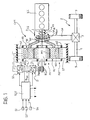
- an internal combustion engine of a motor vehicle for example, a four-stroke engine with four cylinders in line is indicated ICE.
- the engine has an output shaft 1 which is coupled with an axle 2 of a motor vehicle (not shown further) in the manner which will be described below.
- the axle 2 comprises, in known manner, a differential 3 to the driven shafts of which respective axle-shafts 4, associated with respective wheels 5, are connected, in a per se known manner.
- the shaft 1 of the combustion engine ICE is coupled with the axle 2 by means of a transmission system with a continuously variable transmission ratio, generally indicated CVT.
- the transmission system CVT comprises, substantially, two coaxial rotary electrical machines M1 and M2.
- the rotary electrical machine M1 is inside the rotary electrical machine M2 and comprises a first rotor R1 or inner rotor, provided with a multiphase winding W1.
- This winding is, for example, a three-phase winding.
- the rotor R1 has a shaft fixed for rotation with the output shaft 1 of the internal combustion engine ICE.
- the rotary electrical machine M1 further comprises a second rotor R2, or intermediate rotor.
- This rotor has a substantially annular shape and is arranged coaxially around the inner rotor R1.
- the intermediate rotor R2 has, in the vicinity of its inner surface, an arrangement of permanent magnets PM1 operatively cooperating, that is, interacting with the winding W1 of the inner rotor R1.
- the intermediate rotor R2 is, in a sense, shared with the outer rotary electrical machine M2, which also comprises an annular stator ST coaxial with the rotors R1 and R2.
- the stator ST has a multiphase winding W2. This winding may be, in particular, a three-phase winding.
- the radially outermost portion of the intermediate rotor R2 which may also be provided with permanent magnets, cooperates operatively, that is, interacts with the stator ST.
- the intermediate rotor R2 is coupled to the input shaft of the differential 3 of the axle 2 by means of a bell-like element BF and optionally by a reducer SR.
- a first inverter and a second inverter (or alternating-current/direct-current converter) for example, of the above-mentioned VSI type, are indicated I1 and I2 and have their respective alternating-current sides connected to the winding W1 of the inner rotor R1 and to the winding W2 of the stator ST, respectively.
- the alternating-current side of the inverter I1 is connected to the winding W1 of the inner rotor R1 by means of a plurality of brushes B that are in sliding contact with corresponding rings R which are carried by the shaft of the rotor R1 and are connected to the individual phases of the winding W1 in a per se known manner, not shown.
- the inverters I1 and I2 have their respective direct-current sides interconnected by means of a d.c. connection or voltage link L comprising a pair of conductors. At least one capacitive element is arranged in parallel between the connecting conductors L between the two inverters, in a per se known manner; this capacitive element is essential for the operation of the inverters.
- the capacitive element may be constituted by two capacitors C1 and C2 each physically incorporated in one of the two inverters I1 and I2 in parallel with the terminals of the respective direct-current side, or by equivalent arrangements.
- An electronic control unit comprising, for example, a microprocessor, is indicated ECU.
- a plurality of sensors S1 S2, ..., Sn, are connected to this unit and can supply thereto electrical signals indicative of operating conditions of the internal combustion engine ICE and/or of the motor vehicle.
- the sensor S1 may, for example, be a sensor which can supply signals indicative of the rate of rotation ⁇ ICE of the shaft 1 of the internal combustion engine ICE.
- the sensor S2 may be, for example, a sensor which can supply electrical signals indicative of the speed of forward movement of the motor vehicle.
- Further sensors may supply the unit ECU with signals for defining the instantaneous value of the power P ICE delivered by the internal combustion engine ICE, etc.
- the electronic control unit ECU is also connected to the conductors of the d.c. connection or voltage link L between the direct-current sides of the inverters I1 and I2 so as to be able to detect the instantaneous value of the voltage V c in the d.c. link L in operation.
- the unit ECU may be arranged in general to control the engine ICE, to drive the inverters I1 and I2 for the control of the transmission system CVT, and to coordinate these control and driving functions in accordance with predetermined procedures.
- the unit is arranged, in particular, to drive the inverters I1 and I2 in a manner such that, after the internal combustion engine ICE has been started, the voltage V c in the connection L is regulated to a predetermined value which is variable in accordance with predetermined procedures in dependence on the values of the parameters monitored by the sensors S1-Sn, in particular in dependence on the speed of rotation ⁇ ICE of the shaft 1 of the internal combustion engine ICE, on the instantaneous speed of forward movement of the motor vehicle, and on the instantaneous value of the power P ICE delivered by the internal combustion engine.
- the electronic control unit ECU can control the power P DC in the d.c. link L in a manner such that the voltage in the d.c. link corresponds to a predetermined value based on the operating point of the system, the operating point being defined, for example, as already stated above, by the values of the speed of rotation ⁇ ICE of the shaft 1 of the internal combustion engine, by the speed of advance of the motor vehicle, and by the power P ICE delivered by the engine.
- variable-ratio transmission system can ensure the delivery of maximum performance (power output in conditions of maximum difference in speed, as an absolute value, between the shaft 1 of the engine ICE and the output shaft BF of the transmission system CVT) at values close or equal to the maximum value V DC,MAX of the voltage V DC in the d.c. link L.
- the electronic switches of the inverters I1 and I2 can thus have dimensions that are more favourable from an economic point of view if the voltage of best utilization of the switches is arranged to correspond to the value V DC,MAX .
- variable-ratio transmission system CVT of Figure 1 may be defined as "autonomous" since no external supply-voltage source is connected to the connection L between the direct-current sides of the two inverters I1 and I2.
- the electronic control unit ECU can, in particular, be arranged to drive the inverters I1 and I2 in a manner such that, for each operating point, the voltage V DC in the d.c. link L is regulated to the minimum value necessary to impart the desired current values to the windings W1 and W2.
- variable-ratio transmission system CVT The power dimensions of the variable-ratio transmission system CVT can be related substantially to three basic parameters:
- b ⁇ MAX / ⁇ ICE , MAX
- ⁇ MAX has the meaning already defined above
- ⁇ ICE,MAX is the rate of rotation of the shaft of the internal combustion engine ICE at which the maximum power P ICE,MAX is delivered.
- T OUT,MAX T ICE , MAX ⁇ r b
- Tests and investigations carried out by the inventors have identified a criterion for the selection of the dimensions of the system CVT which can minimize the production cost of the inverters I1 and I2 and of the entire system CVT.
- This criterion can easily be expressed as a function of the above-defined ratios b and r.
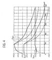
- Figure 2 shows, as a function of the rate of rotation ⁇ OUT , the curve of the output torque T OUT of the transmission system CVT corresponding to the curves, shown therein, of the torque T ICE output by the internal combustion engine ICE and of the torque T EXT applied to the intermediate rotor R2 across the air gap defined between the rotor R2 and the stator ST.
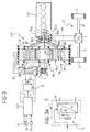
- Figure 3 shows a variant of the system described above with reference to Figure 1 .
- an auxiliary electrical-energy storage system is connected to the d.c. link L.
- this storage system comprises a plurality of electrical accumulators 11 and a bidirectional d.c./d.c. converter 12 which is controlled by the unit ECU in a manner such that the voltage in the d.c. link L is regulated according to the operating point, as described above.
- the converter 12 may be of the so-called "buck-boost” type, or of the "step-up” type.
- the interfacing with the electrical-energy storage system enables the performance characteristics of the system to be improved considerably for given dimensions of the electromechanical portion, but limits the power exchanged with the storage system and hence the cost of the d.c./d.c. converter 12.
- auxiliary electrical energy even only in a transitory manner, can result in a corresponding increase in the maximum power which can be delivered to the wheels, in particular for angular velocities greater than ⁇ base .
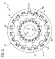
- Figure 5 shows a variant.
- parts and elements which have already been described have again been attributed the same alphabetical and/or numerical references that were used above.
- the first machine M1 and the second machine M2 are advantageously machines of the reluctance type.
- one or other or both of these machines M1, M2 may be of the so-called "switched reluctance" type.
- An example is shown in Figure 5 in which both the inner machine M1 and the outer machine M2 are of this type.
- the first and/or the second electrical machine are of the synchronous or variable reluctance type.
- An example is shown in Figure 6 in which the intermediate rotor R2 is formed in a manner such that both of the machines M1 and M2 are of the synchronous reluctance type.
- the intermediate rotor R2 may be laminated in a transverse direction (plates perpendicular to the axis of rotation), as in the embodiments shown in Figures 5 and 6 , or may be laminated longitudinally, that is, axially (plates parallel to the axis of rotation), as in the embodiment shown in Figure 7 .
- This drawing shows a solution in which the inner machine M1 and the outer machine M2 are both of the synchronous reluctance type with axial lamination of the intermediate rotor.
- the inner machine and/or the outer machine may be synchronous reluctance machines according to prior Italian patent 1,276,487 , to which reference should be made.
- the stator ST and/or the first rotor R1 has an even number n s of slots per pair of poles
- the intermediate rotor R2 has an even number n r of equivalent slots per pair of poles
- the following relationships apply between the numbers n s and n r :
- n s - n r ⁇ 4
- FIG. 8 An embodiment of this type is shown in Figure 8 .
- This drawing shows a solution in which the inner electrical machine M1 and the outer electrical machine M2 are both synchronous reluctance machines and hence substantially of the type of Figure 6 and the intermediate rotor R2 has permanent phase-advancing magnets M.
- the inner electrical machine M1 and/or the outer electrical machine M2 may be sampled-permeance machines formed in accordance with prior International Patent Application PCT/EP02/02172 to which reference should be made.
- the expression "sampled-permeance machines” means specifically machines formed in accordance with the said prior International Patent Application.
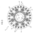
- FIG 9 shows graphically an embodiment of this type in which both of the machines M1 and M2 are sampled-permeance machines.
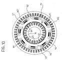
- the inner machine M1 has surface magnets SM and the outer machine M2 is of the reluctance type ( Figure 10 ).
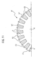
- the teeth D of the inner rotor R1 which define the slots in which the winding W1 is positioned, may have respective peripheral recesses or grooves FS that are free of conductors or magnets (so-called false slots), facing the air-gap, for reducing cogging, as shown on an enlarged scale in Figure 11 .
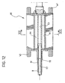
- FIGS 12 and 13 show an embodiment of the inner rotor R1 with cooling by circulation of fluid.
- the rotor R1 shown therein has a central shaft/hub 52 in which a central axial duct 53 is formed for a flow of coolant fluid.
- This duct 53 communicates at one end (the right-hand end as seen in Figure 12 ) with a plurality of radially outer ducts 54 which surround it.
- the arrangement is such that, in operation, the coolant fluid flows through the ducts 54 in the opposite direction to the flow in the central duct 53.
- the outer ducts 54 which in practice are parallel to one another, communicate at one end with an annular manifold 55 which extends around the inlet portion of the central duct 53.
- a single annular jacket may be provided instead of the outer ducts 54.
- a system of this type can be arranged to bring about starting of the combustion engine ICE by means of the electrical machines M1 and M2 of the unit CVT by using this unit as a motor or torque source.
- the shaft 1 of the combustion engine ICE is coupled to the shaft 52 ( Figure 14 ) of the inner rotor R1 of a unit of this type by means of an (optional) torsional ("flexible") coupling 51.
- the coupling 51 and the shaft 1 of the engine ICE together represent the torsional "load” 50 "seen” by the shaft 52 of the unit CVT, the shaft 52 representing the output of the unit CVT during the operation to start the engine ICE.
- the electronic control unit ECU is arranged to bring about rotation of the output 52 of the unit CVT in both directions so that it develops a torque of predetermined value.
- the control unit ECU is arranged, in particular, to bring about activation of the unit CVT in a manner such that the output 52 thereof rotates in a predetermined initial direction and applies to the load 50 a torque T OUT having a predetermined value T start .
- the value of the initial torque T start is less than the value necessary to cause rotation of the load 50 to start and, in particular, less than the value necessary to bring about the so-called "breakaway” or “release” of the internal combustion engine, that is, to overcome the forces which oppose the movement of the pistons in the cylinders.
- the value of the torque T start is however sufficient to bring about a condition of resilient torsion of the load 50, that is, of the unit formed by the torsional coupling 51 and by the shaft 1 of the engine ICE.
- the application of the torque T start to the load 50 thus brings about a storage of elastic energy therein.
- the amount of torsion produced in the load increases up to a maximum value which corresponds substantially to the reduction to zero of the angular velocity ⁇ OUT of the output 52 of the unit CVT.
- This velocity can be detected by means of a sensor Sx connected to an input of the control unit ECU.
- the control unit ECU drives the unit CVT in a manner such that its output 52 now rotates in the opposite direction to the previous direction and develops a predetermined torque T OUT (now having, for example, a value Tstart).
- T OUT now having, for example, a value Tstart.
- the control unit ECU may then advantageously be arranged to activate the unit CVT so as to apply to the load 50 successive torque pulses of alternating sign, and hence alternately forwards and in reverse, suitably in time with the detected curve of the angular velocity ⁇ OUT of the output 52 of that unit so that, for each reversal of the sign of the torque T OUT , the load 50 is subjected to a new resultant torque corresponding to the sum of the torque momentarily applied by the unit CVT and of a gradually increasing twisting moment generated by the resilient return of the load from the previous resilient torsion condition.
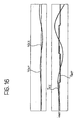
- a type of "amplification" effect on the torque T ICE applied to the shaft of the internal combustion engine ICE is thus created, as shown by way of example and qualitatively in the graphs of Figure 16 .
- the starting operation comprises, after the initial "breakaway” stage, a second stage in which the rotation is accelerated until the so-called self-sustaining speed is reached.
- the unit CVT is therefore activated in the opposite direction to the normal direction of rotation envisaged for the shaft 1 of the engine ICE for a limited angular displacement and with a predefined low torque To (see the graphs of Figure 17 at time t 0 ).
- the unit CVT is then activated in the normal direction of rotation of the shaft of the engine ICE.
- a first advantage is an increase in the angular displacement of the shaft 1 in order to reach the first position of maximum resisting torque T R (T.D.C. - top dead centre) .
- the second advantage is the storage of (pseudo)-elastic energy which can be achieved as a result of the compression of the gas in one or more of the cylinders which have their intake/exhaust valves closed at this stage.
- the graphs of Figure 17 show examples of time curves of some quantities, starting from the time to at which the second stage of the starting procedure begins.
Landscapes
- Engineering & Computer Science (AREA)
- Mechanical Engineering (AREA)
- Power Engineering (AREA)
- Transportation (AREA)
- Chemical & Material Sciences (AREA)
- Combustion & Propulsion (AREA)
- Life Sciences & Earth Sciences (AREA)
- Sustainable Energy (AREA)
- Sustainable Development (AREA)
- General Engineering & Computer Science (AREA)
- Hybrid Electric Vehicles (AREA)
- Control Of Transmission Device (AREA)
- Control Of Driving Devices And Active Controlling Of Vehicle (AREA)
- Transmissions By Endless Flexible Members (AREA)
- Circuits Of Receivers In General (AREA)
- Non-Deflectable Wheels, Steering Of Trailers, Or Other Steering (AREA)
- Piles And Underground Anchors (AREA)
Applications Claiming Priority (3)
| Application Number | Priority Date | Filing Date | Title |
|---|---|---|---|
| IT2001TO001171A ITTO20011171A1 (it) | 2001-12-14 | 2001-12-14 | Sistema di trasmissione a rapporto variabile in modo continuo. |
| ITTO20011171 | 2001-12-14 | ||
| PCT/EP2002/014094 WO2003051660A2 (en) | 2001-12-14 | 2002-12-11 | A transmission system with a continuously variable transmission ratio |
Publications (2)
| Publication Number | Publication Date |
|---|---|
| EP1456048A2 EP1456048A2 (en) | 2004-09-15 |
| EP1456048B1 true EP1456048B1 (en) | 2010-01-27 |
Family
ID=11459337
Family Applications (1)
| Application Number | Title | Priority Date | Filing Date |
|---|---|---|---|
| EP02796610A Expired - Lifetime EP1456048B1 (en) | 2001-12-14 | 2002-12-11 | A transmission system with a continuously variable transmission ratio |
Country Status (7)
| Country | Link |
|---|---|
| US (1) | US7395143B2 (it) |
| EP (1) | EP1456048B1 (it) |
| AT (1) | ATE456478T1 (it) |
| AU (1) | AU2002361394A1 (it) |
| DE (1) | DE60235258D1 (it) |
| IT (1) | ITTO20011171A1 (it) |
| WO (1) | WO2003051660A2 (it) |
Cited By (1)
| Publication number | Priority date | Publication date | Assignee | Title |
|---|---|---|---|---|
| DE102023112726A1 (de) * | 2023-05-15 | 2024-11-21 | Bayerische Motoren Werke Aktiengesellschaft | Antrieb und Verfahren zum Betrieb eines Antriebs |
Families Citing this family (18)
| Publication number | Priority date | Publication date | Assignee | Title |
|---|---|---|---|---|
| GB0410135D0 (en) * | 2004-05-06 | 2004-06-09 | Ricardo Uk Ltd | Cylinder pressure sensor |
| ATE407869T1 (de) | 2006-02-15 | 2008-09-15 | Fiat Ricerche | Fahrzeugrad |
| JP4693865B2 (ja) * | 2007-08-27 | 2011-06-01 | 株式会社豊田中央研究所 | 動力伝達装置 |
| RU2362687C1 (ru) * | 2007-10-30 | 2009-07-27 | Владимир Владимирович Дружков | Бесступенчатый электромашинный гибридный вариатор с цифровым управлением |
| EP2072311A1 (en) | 2007-12-18 | 2009-06-24 | Nederlandse Organisatie voor toegepast- natuurwetenschappelijk onderzoek TNO | Drive system for hybrid vehicle |
| JP4505521B2 (ja) * | 2008-07-09 | 2010-07-21 | 本田技研工業株式会社 | 動力装置 |
| JP4505524B2 (ja) * | 2008-07-22 | 2010-07-21 | 本田技研工業株式会社 | 動力装置 |
| CN101388586B (zh) * | 2008-09-27 | 2011-10-05 | 中国科学院电工研究所 | 一种集成有双速比输出机构的电力无级变速器 |
| JP5730740B2 (ja) * | 2011-10-19 | 2015-06-10 | トヨタ自動車株式会社 | 回転電機 |
| GB2516644A (en) * | 2013-07-26 | 2015-02-04 | Ricardo Uk Ltd | A Magnetic Coupling |
| US9130433B2 (en) * | 2013-11-14 | 2015-09-08 | Arm Limited | Electronically controlled universal motor |
| CN104648111A (zh) * | 2013-11-21 | 2015-05-27 | 扬州市新港电机有限公司 | 一种汽车电动发电一体化无级调速系统 |
| CN103991374B (zh) * | 2014-05-08 | 2016-09-14 | 江苏大学 | 基于双转子电机动力耦合器的混合动力车辆系统切换控制方法 |
| EP3007336B1 (en) | 2014-10-07 | 2016-11-30 | C.R.F. Società Consortile per Azioni | Synchronous electric machine with two rotors |
| JP6314849B2 (ja) * | 2015-01-15 | 2018-04-25 | トヨタ自動車株式会社 | 車両制御装置 |
| ITUB201586605U1 (it) * | 2015-10-28 | 2017-04-28 | D&M Holding S P A | Gruppo ad alimentazione elettrica per la propulsione di un veicolo terrestre |
| US10730394B2 (en) * | 2016-10-04 | 2020-08-04 | Ford Global Technologies, Llc | Electromechanical integrated machine for electrified vehicles |
| US11923733B2 (en) * | 2020-08-28 | 2024-03-05 | Quantentech Limited | High efficiency high density motor and generator with multiple airgaps |
Family Cites Families (6)
| Publication number | Priority date | Publication date | Assignee | Title |
|---|---|---|---|---|
| US4729494A (en) | 1985-04-12 | 1988-03-08 | Peillon Jean Pierre | Container for liquid gas |
| US4862009A (en) * | 1988-03-22 | 1989-08-29 | General Electric Company | Combined electric starter and alternator system using a permanent magnet synchronous machine |
| JP2754886B2 (ja) * | 1990-08-24 | 1998-05-20 | トヨタ自動車株式会社 | 永久磁石型交流サーボモータ制御装置 |
| US6018694A (en) * | 1996-07-30 | 2000-01-25 | Denso Corporation | Controller for hybrid vehicle |
| WO1998004431A1 (en) | 1996-07-30 | 1998-02-05 | Denso Corporation | Hybrid car controller |
| DE19856551A1 (de) * | 1998-12-08 | 2000-06-15 | Heidenhain Gmbh Dr Johannes | Verfahren und Schaltungsanordnung zur Anpassung der Zwischenkreisspannung an die Versorgungsspannung |
-
2001
- 2001-12-14 IT IT2001TO001171A patent/ITTO20011171A1/it unknown
-
2002
- 2002-12-11 EP EP02796610A patent/EP1456048B1/en not_active Expired - Lifetime
- 2002-12-11 US US10/498,556 patent/US7395143B2/en not_active Expired - Lifetime
- 2002-12-11 AT AT02796610T patent/ATE456478T1/de not_active IP Right Cessation
- 2002-12-11 AU AU2002361394A patent/AU2002361394A1/en not_active Abandoned
- 2002-12-11 DE DE60235258T patent/DE60235258D1/de not_active Expired - Lifetime
- 2002-12-11 WO PCT/EP2002/014094 patent/WO2003051660A2/en not_active Ceased
Cited By (1)
| Publication number | Priority date | Publication date | Assignee | Title |
|---|---|---|---|---|
| DE102023112726A1 (de) * | 2023-05-15 | 2024-11-21 | Bayerische Motoren Werke Aktiengesellschaft | Antrieb und Verfahren zum Betrieb eines Antriebs |
Also Published As
| Publication number | Publication date |
|---|---|
| WO2003051660A2 (en) | 2003-06-26 |
| EP1456048A2 (en) | 2004-09-15 |
| ITTO20011171A0 (it) | 2001-12-14 |
| DE60235258D1 (de) | 2010-03-18 |
| WO2003051660A3 (en) | 2003-12-31 |
| AU2002361394A1 (en) | 2003-06-30 |
| US20050085975A1 (en) | 2005-04-21 |
| ITTO20011171A1 (it) | 2003-06-16 |
| ATE456478T1 (de) | 2010-02-15 |
| US7395143B2 (en) | 2008-07-01 |
Similar Documents
| Publication | Publication Date | Title |
|---|---|---|
| EP1456048B1 (en) | A transmission system with a continuously variable transmission ratio | |
| EP1085644B1 (en) | Hybrid car and dynamo-electric machine | |
| EP2316682B1 (en) | Power device | |
| JP4818368B2 (ja) | ハイブリッド車両 | |
| US9925889B2 (en) | Electric machine for hybrid powertrain with dual voltage power system | |
| US10581287B2 (en) | Permanent magnet electric machine with variable magnet orientation | |
| KR100998542B1 (ko) | 보조 기계 구동 장치 | |
| US8647230B2 (en) | Moving apparatus | |
| US20170063187A1 (en) | Electric machine for hybrid powertrain with engine belt drive | |
| US20020047418A1 (en) | Compact and reliable structure of multi-rotor synchronous machine | |
| CN103219842A (zh) | 双机械端口机电能量变换器 | |
| EP1130740B1 (en) | Hybrid electric vehicle with a permanent magnetic type dynamo-electric machine | |
| US11855573B2 (en) | Large dynamic range electric motor | |
| US20120122629A1 (en) | Power plant | |
| US11581842B2 (en) | Magnet temperature estimating device for motor and hybrid vehicle provided with the same | |
| EP3859293A1 (en) | Magnet temperature estimating device for motor, hybrid vehicle provided with the same, and method of estimating magnet temperature | |
| RU2376158C2 (ru) | Электромеханическая трансмиссия | |
| JP3752487B2 (ja) | ハイブリッド車及び回転電機 | |
| JPH07322413A (ja) | 回転電機制御装置および電気自動車 | |
| JP2009130959A (ja) | 回転電機及び回転電機を用いた電気車両 | |
| KR970000792A (ko) | 전기차량을 구동하기 위한 시스템 및 그 방법 | |
| JP5171785B2 (ja) | 動力装置 | |
| RU2075816C1 (ru) | Индукторный электродвигатель | |
| RO137762A1 (ro) | Ansamblu-motor cu recuperare de energie | |
| JP2008125195A (ja) | 電動モータおよびハイブリット車両 |
Legal Events
| Date | Code | Title | Description |
|---|---|---|---|
| PUAI | Public reference made under article 153(3) epc to a published international application that has entered the european phase |
Free format text: ORIGINAL CODE: 0009012 |
|
| 17P | Request for examination filed |
Effective date: 20040712 |
|
| AK | Designated contracting states |
Kind code of ref document: A2 Designated state(s): AT BE BG CH CY CZ DE DK EE ES FI FR GB GR IE IT LI LU MC NL PT SE SI SK TR |
|
| AX | Request for extension of the european patent |
Extension state: AL LT LV MK RO |
|
| RIN1 | Information on inventor provided before grant (corrected) |
Inventor name: RE FIORENTIN, STEFANO Inventor name: DEL GOBBO, ANGELA Inventor name: VILLATA, FRANCO Inventor name: TARQUINIO, LIBORIO Inventor name: PELLEGRINO, GIAN MARIO Inventor name: FRATTA, ANTONINO Inventor name: VAGATI, ALFREDO |
|
| GRAP | Despatch of communication of intention to grant a patent |
Free format text: ORIGINAL CODE: EPIDOSNIGR1 |
|
| RIN1 | Information on inventor provided before grant (corrected) |
Inventor name: FRATTA, ANTONINO Inventor name: VILLATA, FRANCO Inventor name: VAGATI, ALFREDO Inventor name: RE FIORENTIN, STEFANO Inventor name: DEL GOBBO, ANGELA Inventor name: TARQUINIO, LIBORIO Inventor name: PELLEGRINO, GIAN MARIO |
|
| RIC1 | Information provided on ipc code assigned before grant |
Ipc: F02N 11/04 20060101ALI20091014BHEP Ipc: B60K 6/365 20071001AFI20091014BHEP Ipc: B60K 6/48 20071001ALI20091014BHEP Ipc: H02K 51/00 20060101ALI20091014BHEP |
|
| GRAS | Grant fee paid |
Free format text: ORIGINAL CODE: EPIDOSNIGR3 |
|
| GRAA | (expected) grant |
Free format text: ORIGINAL CODE: 0009210 |
|
| AK | Designated contracting states |
Kind code of ref document: B1 Designated state(s): AT BE BG CH CY CZ DE DK EE ES FI FR GB GR IE IT LI LU MC NL PT SE SI SK TR |
|
| REG | Reference to a national code |
Ref country code: GB Ref legal event code: FG4D |
|
| REG | Reference to a national code |
Ref country code: CH Ref legal event code: EP |
|
| REG | Reference to a national code |
Ref country code: IE Ref legal event code: FG4D |
|
| REF | Corresponds to: |
Ref document number: 60235258 Country of ref document: DE Date of ref document: 20100318 Kind code of ref document: P |
|
| REG | Reference to a national code |
Ref country code: NL Ref legal event code: VDEP Effective date: 20100127 |
|
| PG25 | Lapsed in a contracting state [announced via postgrant information from national office to epo] |
Ref country code: AT Free format text: LAPSE BECAUSE OF FAILURE TO SUBMIT A TRANSLATION OF THE DESCRIPTION OR TO PAY THE FEE WITHIN THE PRESCRIBED TIME-LIMIT Effective date: 20100127 |
|
| PG25 | Lapsed in a contracting state [announced via postgrant information from national office to epo] |
Ref country code: PT Free format text: LAPSE BECAUSE OF FAILURE TO SUBMIT A TRANSLATION OF THE DESCRIPTION OR TO PAY THE FEE WITHIN THE PRESCRIBED TIME-LIMIT Effective date: 20100527 Ref country code: NL Free format text: LAPSE BECAUSE OF FAILURE TO SUBMIT A TRANSLATION OF THE DESCRIPTION OR TO PAY THE FEE WITHIN THE PRESCRIBED TIME-LIMIT Effective date: 20100127 Ref country code: ES Free format text: LAPSE BECAUSE OF FAILURE TO SUBMIT A TRANSLATION OF THE DESCRIPTION OR TO PAY THE FEE WITHIN THE PRESCRIBED TIME-LIMIT Effective date: 20100508 |
|
| PG25 | Lapsed in a contracting state [announced via postgrant information from national office to epo] |
Ref country code: FI Free format text: LAPSE BECAUSE OF FAILURE TO SUBMIT A TRANSLATION OF THE DESCRIPTION OR TO PAY THE FEE WITHIN THE PRESCRIBED TIME-LIMIT Effective date: 20100127 Ref country code: SI Free format text: LAPSE BECAUSE OF FAILURE TO SUBMIT A TRANSLATION OF THE DESCRIPTION OR TO PAY THE FEE WITHIN THE PRESCRIBED TIME-LIMIT Effective date: 20100127 |
|
| PG25 | Lapsed in a contracting state [announced via postgrant information from national office to epo] |
Ref country code: BE Free format text: LAPSE BECAUSE OF FAILURE TO SUBMIT A TRANSLATION OF THE DESCRIPTION OR TO PAY THE FEE WITHIN THE PRESCRIBED TIME-LIMIT Effective date: 20100127 Ref country code: SE Free format text: LAPSE BECAUSE OF FAILURE TO SUBMIT A TRANSLATION OF THE DESCRIPTION OR TO PAY THE FEE WITHIN THE PRESCRIBED TIME-LIMIT Effective date: 20100127 Ref country code: GR Free format text: LAPSE BECAUSE OF FAILURE TO SUBMIT A TRANSLATION OF THE DESCRIPTION OR TO PAY THE FEE WITHIN THE PRESCRIBED TIME-LIMIT Effective date: 20100428 Ref country code: EE Free format text: LAPSE BECAUSE OF FAILURE TO SUBMIT A TRANSLATION OF THE DESCRIPTION OR TO PAY THE FEE WITHIN THE PRESCRIBED TIME-LIMIT Effective date: 20100127 Ref country code: CY Free format text: LAPSE BECAUSE OF FAILURE TO SUBMIT A TRANSLATION OF THE DESCRIPTION OR TO PAY THE FEE WITHIN THE PRESCRIBED TIME-LIMIT Effective date: 20100127 |
|
| PG25 | Lapsed in a contracting state [announced via postgrant information from national office to epo] |
Ref country code: CZ Free format text: LAPSE BECAUSE OF FAILURE TO SUBMIT A TRANSLATION OF THE DESCRIPTION OR TO PAY THE FEE WITHIN THE PRESCRIBED TIME-LIMIT Effective date: 20100127 Ref country code: SK Free format text: LAPSE BECAUSE OF FAILURE TO SUBMIT A TRANSLATION OF THE DESCRIPTION OR TO PAY THE FEE WITHIN THE PRESCRIBED TIME-LIMIT Effective date: 20100127 Ref country code: BG Free format text: LAPSE BECAUSE OF FAILURE TO SUBMIT A TRANSLATION OF THE DESCRIPTION OR TO PAY THE FEE WITHIN THE PRESCRIBED TIME-LIMIT Effective date: 20100427 |
|
| PLBE | No opposition filed within time limit |
Free format text: ORIGINAL CODE: 0009261 |
|
| STAA | Information on the status of an ep patent application or granted ep patent |
Free format text: STATUS: NO OPPOSITION FILED WITHIN TIME LIMIT |
|
| 26N | No opposition filed |
Effective date: 20101028 |
|
| PG25 | Lapsed in a contracting state [announced via postgrant information from national office to epo] |
Ref country code: DK Free format text: LAPSE BECAUSE OF FAILURE TO SUBMIT A TRANSLATION OF THE DESCRIPTION OR TO PAY THE FEE WITHIN THE PRESCRIBED TIME-LIMIT Effective date: 20100127 |
|
| PG25 | Lapsed in a contracting state [announced via postgrant information from national office to epo] |
Ref country code: MC Free format text: LAPSE BECAUSE OF NON-PAYMENT OF DUE FEES Effective date: 20101231 |
|
| REG | Reference to a national code |
Ref country code: CH Ref legal event code: PL |
|
| GBPC | Gb: european patent ceased through non-payment of renewal fee |
Effective date: 20101211 |
|
| PG25 | Lapsed in a contracting state [announced via postgrant information from national office to epo] |
Ref country code: CH Free format text: LAPSE BECAUSE OF NON-PAYMENT OF DUE FEES Effective date: 20101231 Ref country code: IE Free format text: LAPSE BECAUSE OF NON-PAYMENT OF DUE FEES Effective date: 20101211 Ref country code: LI Free format text: LAPSE BECAUSE OF NON-PAYMENT OF DUE FEES Effective date: 20101231 |
|
| PG25 | Lapsed in a contracting state [announced via postgrant information from national office to epo] |
Ref country code: GB Free format text: LAPSE BECAUSE OF NON-PAYMENT OF DUE FEES Effective date: 20101211 |
|
| PG25 | Lapsed in a contracting state [announced via postgrant information from national office to epo] |
Ref country code: LU Free format text: LAPSE BECAUSE OF NON-PAYMENT OF DUE FEES Effective date: 20101211 |
|
| PG25 | Lapsed in a contracting state [announced via postgrant information from national office to epo] |
Ref country code: TR Free format text: LAPSE BECAUSE OF FAILURE TO SUBMIT A TRANSLATION OF THE DESCRIPTION OR TO PAY THE FEE WITHIN THE PRESCRIBED TIME-LIMIT Effective date: 20100127 |
|
| REG | Reference to a national code |
Ref country code: FR Ref legal event code: PLFP Year of fee payment: 14 |
|
| REG | Reference to a national code |
Ref country code: FR Ref legal event code: PLFP Year of fee payment: 15 |
|
| REG | Reference to a national code |
Ref country code: FR Ref legal event code: PLFP Year of fee payment: 16 |
|
| PGFP | Annual fee paid to national office [announced via postgrant information from national office to epo] |
Ref country code: DE Payment date: 20211210 Year of fee payment: 20 Ref country code: FR Payment date: 20211230 Year of fee payment: 20 |
|
| PGFP | Annual fee paid to national office [announced via postgrant information from national office to epo] |
Ref country code: IT Payment date: 20211111 Year of fee payment: 20 |
|
| REG | Reference to a national code |
Ref country code: DE Ref legal event code: R071 Ref document number: 60235258 Country of ref document: DE |