EP1457140A2 - Armstütze, insbesondere für Büro- und Drehstühle - Google Patents
Armstütze, insbesondere für Büro- und Drehstühle Download PDFInfo
- Publication number
- EP1457140A2 EP1457140A2 EP04004791A EP04004791A EP1457140A2 EP 1457140 A2 EP1457140 A2 EP 1457140A2 EP 04004791 A EP04004791 A EP 04004791A EP 04004791 A EP04004791 A EP 04004791A EP 1457140 A2 EP1457140 A2 EP 1457140A2
- Authority
- EP
- European Patent Office
- Prior art keywords
- insert
- armrest
- locking
- locking pin
- armrest according
- Prior art date
- Legal status (The legal status is an assumption and is not a legal conclusion. Google has not performed a legal analysis and makes no representation as to the accuracy of the status listed.)
- Granted
Links
- 230000000903 blocking effect Effects 0.000 claims description 20
- 238000002347 injection Methods 0.000 claims description 2
- 239000007924 injection Substances 0.000 claims description 2
- 238000004519 manufacturing process Methods 0.000 abstract description 3
- 230000001419 dependent effect Effects 0.000 description 2
- 230000006835 compression Effects 0.000 description 1
- 238000007906 compression Methods 0.000 description 1
- 238000011161 development Methods 0.000 description 1
- 230000018109 developmental process Effects 0.000 description 1
- 238000010586 diagram Methods 0.000 description 1
- 210000003746 feather Anatomy 0.000 description 1
- 108700039855 mouse a Proteins 0.000 description 1
- 230000001960 triggered effect Effects 0.000 description 1
Images


Classifications
-
- A—HUMAN NECESSITIES
- A47—FURNITURE; DOMESTIC ARTICLES OR APPLIANCES; COFFEE MILLS; SPICE MILLS; SUCTION CLEANERS IN GENERAL
- A47C—CHAIRS; SOFAS; BEDS
- A47C1/00—Chairs adapted for special purposes
- A47C1/02—Reclining or easy chairs
- A47C1/022—Reclining or easy chairs having independently-adjustable supporting parts
- A47C1/03—Reclining or easy chairs having independently-adjustable supporting parts the parts being arm-rests
Definitions
- the invention relates to an armrest, especially for an office or swivel chair with adjustability in depth, width and angle, whereby in a two-part armrest with a lower part and an upper shell the armrest support is firmly connected insert piece, wherein the lower part has at least one window through which connecting means are guided, the armrest support with the insert connect, and with the lower part opposite the insert movable and in the selected position with provided on the insert Locking means can be fixed.
- Office or swivel chairs often point approximately at right angles to the backrest arranged armrests on, with one of the backrest assigned rear dome and a front dome with an armrest stand are attached to the seat frame. It is known to such armrests training height adjustable so that the user of the chair the Height of the armrests can be adjusted according to your wishes.
- Other positions as for example due to changing positions of the arm with the work hand - as a result of a constant change from the keyboard to the mouse a computer workstation - are conditional on this arrangement not to.
- Such armrests are, for example, from German utility models DE 298 09 099 or DE 299 01 666 known. These armrests are on an armrest stand on the seat frame of the chair essentially held at right angles to a backrest, height adjustable arranged, and with an armrest with armrest pad provided, the one facing the backrest rear and one has front dome facing away from this.
- This armrest is formed by a hollow body consisting of an upper part with armrest pads and a bottom part with bottom plate joined together positively and on an upper end plate of the armrest support is put on.
- the adjustment options described there are, however limited because the locking means only allow limited adjustments.
- the longitudinal slide is together for longitudinal and transverse adjustment assembled with a cross slide to the lower part of the armrest, that a cavity is formed between the two.
- An insert is provided in the cavity, with the armrest support is firmly connected, and has transverse grooves in which on the Engage the guide rails provided on the inside of the cross slide and thus define the mobility of the cross slide.
- the necessary to attach the insert to the armrest support Connection screws are through corresponding elongated holes in the Longitudinal slide or guided in the slide insert. These oblong holes extend in the longitudinal slide in the longitudinal direction of the armrest, while the slots in the sled insert are at right angles to it. Compared to this insert, the lower part is at least in Adjustable lengthways to the armrest and transversely to it.
- the longitudinal slide is designed as a recessed trough plate, the Locking troughs are directed towards the interior of the cavity. With these Locking troughs interact at least one locking pin that the insert has, and aligned perpendicular to the longitudinal slide is. The head of this locking pin engages in one of these locking troughs and fixes the corresponding position of the armrest, for what the locking pin in its locking position in a by elastic forces the selected notches are pressed.
- the locking pin is advantageous designed as slidable in the axial direction and with a the compression spring supported on the insert is pressed into the locking position.
- the arrangement of the recessed recesses, distributed over an area of the Inside of the longitudinal slide, ensures that next to the Longitudinal movement also fixed the transverse movement by means of the locking pin becomes.
- the insert is designed like a bridge and the Slide insert arranged as a separate part in the cavity of the bridge is, so the sled insert in this cavity of the bridge-like Insert piece is rotatable relative to this, wherein this slide insert has the transverse grooves with the guide rails of the cross slide interact, making the armrest one Swiveling of the cross slide relative to the insert follows.
- the carriage insert is provided with a second locking pin, the extends at right angles to it.
- a blocking device for this purpose provided with the at least the longitudinal and transverse movement fixing locking pin can be locked in its axial mobility can.
- the locking pin is opposite to the locking head End through the insert or the slide insert so that this end at least on the body of the insert comes out when changing the armrest position.
- the one Backdrop that is set by moving or pivoting can be that the free end of the locking pin stands up or goes free. If this end is up, the locking pin cannot be lowered be, and the locking position is blocked; the locking pin goes free, it can be lowered so that the locking head moves out slide the initially set recess and into a new recess can intervene.
- This armrest can be produced economically by that all or at least some of the individual parts are plastic injection molded parts are trained. This allows a rational and so inexpensive manufacturing that leads to dimensionally accurate parts. The dimensional accuracy guaranteed in this way also ensures that the armrest assembly can be carried out economically can.
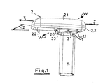
- An armrest for an office or swivel chair is with an armrest 2 placed on an armrest support 1, which by means of a Armrest holder 4 on the frame of the swivel or office chair (not shown in more detail).
- the armrest wearer 1 inserted into the armrest holder 4 so that a Height adjustment mechanism (not shown) the adjustment of the altitude allows the armrest to the size of the user.
- the armrest holder 4 sleeve-shaped and takes the armrest support 1 in Art a telescopic guide.
- the height adjustment mechanism is in the armrest holder 4 arranged and triggered with the release lever 3.
- the armrest support 1 points out of the armrest holder 4 led out, free end on an upper end plate 1.1, the is provided with means for fastening the armrest 2.
- This armrest 2 is with fastening screws 2.3 on the longitudinal slide 22 of the lower part 20 set.
- the armrest 2 itself is with the Upholstery pad 2.1 and a circumferential overlap 2.2.
- the armrest set in this way follows all movements of this longitudinal slide 22.
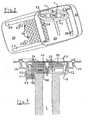
- an insert 30 is arranged over the fastening screws 1.2 screwed to the upper end plate 1.1 of the arm support bracket 1 is, these fastening screws 1.2 through elongated holes 28 are guided in the bottom of the insert 30.
- This insert 30 is thus - apart from the height adjustability - as a quasi-rack to watch.
- the lower part 20 of the armrest 2 is opposite this insert 30 freely movable, its storage can be as floating be considered.
- this has an insert receptacle 26 which is covered with the longitudinal slide 22.
- This longitudinal slide 22nd is by means of the lower part screw connections formed by 4 lower part screws 21 screwed to the lower part receptacle 26, the Lower part screws 21 in the longitudinal direction of the armrest 2 aligned elongated holes 23 extend. This makes it longitudinally movable of the longitudinal slide 22 relative to the insert receptacle 26 reached, the longitudinal slide 22 provided with side guides 25 is.
- a first locking pin 35 is provided on the insert 30, arranged at right angles to the insert 30 is. The end of this locking pin which interacts with the longitudinal slide 22 35 is designed as a locking head 36, while the opposite free pin end 37 through the body of the insert so is guided that the locking pin is movable in its axial direction.
- Spring 38 is provided, which is supported on the insert body 30, so that the locking head 36 is pressed in the direction of the longitudinal slide 22.
- the insert 30 is in excluding its middle like a bridge.
- a cross slide 40 is arranged in the cavity 31. This is guided in transverse guides 27, for which purpose in the underside of the cross slide 40 transverse grooves 41 are provided in which the transverse guides 27 intervene.
- transverse guides 27 for which purpose in the underside of the cross slide 40 transverse grooves 41 are provided in which the transverse guides 27 intervene.
- This bridge-like cavity 31 and the one therein are advantageous used cross slide 40 (partially) cylindrical, so that the lower part 20 can also be pivoted relative to the insert 30 (see Fig. 2).
- This training will be essentially horizontal Another degree of freedom for mobility has been achieved.
- the locking head 46 with locking troughs 32 in the bridge-like Interact cavity.
- These locking troughs 32 are arcuate distributed, the radius of the circle the distance of the second locking pin 45 from the center of the cavity 31 forming Cylinder corresponds.
- the locking head 46 cooperate with one of the locking recesses 32 so that the pivoting movement is fixed.
- the detent head 46 is replaced by the insert 30 facing end of the second locking pin 45 formed during its opposite, free end through the body of the cross slide 40 is guided, the locking head 46 by a in the cross slide 40 supported spring 48 in the selected one of the locking troughs 32 is pressed.
- the fixation is released in the same way Way how in connection with releasing the fixation of the longitudinal or transverse movement described.
- a blocking lever 50 is provided so that its at the end of the lever provided backdrop 51 under or by the body of the Insert 30 or the cross slide 40 guided free ends / ends of the first locking pin 35 and / or the second locking pin 45 so lies that the free ends 37 and 47 are supported on it.
- This support blocks the mobility of the locking pins 35 and 45 in their axial direction, so that forces acting on the armrest 2 the locking heads 36 and 46 with from the corresponding locking troughs 24 or 32 can slide.
- the free movement of the armrest 2 is blocked in the degree of freedom assigned to this locking pin.
- the blocking lever is shifted so that the lower part of the backdrop 51 under the free end 37 or 47 of the locking pin 35 or 45 comes to rest.
- the associated locking head can be assigned to the Sliding recesses 24 and 32 slide so that acting on the armrest 2 Forces these to change the depth or width in the longitudinal direction or shifted in the transverse direction and / or to change the Angular position of the armrest 2 can be pivoted.
- the blocking lever 50 is pivotable. To do so the blocking lever 50 on a stub shaft 52 through the insert receptacle 20 and through the upper end plate 1.1 of the Armrest carrier 1 is guided, and on the positive and non-positive an operating lever 53 is attached so that this on the armrest support 1 is brought out and as a control element for lifting blocking is available.
- the link 51 of the blocking lever 50 can also be designed in this way can that unblock the longitudinal and transverse movement on the one hand and the swiveling movement on the other hand in different Positions of the blocking lever 50 takes place.
- this can also be the case with a (not slide lever.
Landscapes
- Health & Medical Sciences (AREA)
- Dentistry (AREA)
- General Health & Medical Sciences (AREA)
- Seats For Vehicles (AREA)
- Special Chairs (AREA)
- Chair Legs, Seat Parts, And Backrests (AREA)
- Peptides Or Proteins (AREA)
Abstract
wobei die Innenseite des Längsschlittens (22) flächig verteilte Rastmulden (24) aufweist, die mit im Einsatzstück (30) angeordneten und sich rechtwinklig dazu erstreckenden Raststift (35) zusammenwirkend die eingestellten Position der Armauflage (2) fixieren.
Description
- Fig. 1:
- Armauflage (Ansicht - persp. Schema);
- Fig. 2:
- Armauflagen-Unterteil (Untersicht):
- Fig. 3:
- Armauflage (Querschnitt);
- Fig. 4a:
- Armauflage, Raststifte blockiert (Querschnitt),
- Fig. 4b:
- Armauflage, Raststifte entsperrt (Querschnitt);
- Fig. 5:
- Armauflage, Zusammenstellung in Art einer Explosionsdarstellung.
Claims (17)
- Armstütze insbesondere für Bürostuhl mit Verstellbarkeit in Tiefe, Weite und Winkel, wobei in einem Gehäuse mit Unterteil und Oberschale ein mit dem Armlehnenträger fest verbundenes Einsatzstück angeordnet ist, wobei Einsatzstück und Gehäuse zusammenwirkende Rastmitteln aufweisen, und wobei der Längsschieber sowie das Unterteil Ausnehmungen aufweisen, durch welche die Verbindungsmittel von Armlehnenträger und Einsatzplatte geführt sind, dadurch gekennzeichnet, dass das Unterteil (20) der Armauflage (2) aus einem Längsschlitten (22) und einer Einsatzstückaufnahme (26) so zusammengefügt wird, dass ein Hohlraum zwischen beiden gebildet ist, in dem das mit dem Armstützenträger (1) fest verbundene Einsatzstück (30) vorgesehen ist, und dass die Innenseite des Längsschlittens (22) flächig verteilte Rastmulden (24) aufweist, die mit zumindest einem im Einsatzstück (30) angeordneten und sich rechtwinklig dazu erstreckenden Raststift (35) zusammenwirkend eine Fixierung der eingestellten Position der Armauflage (2) erlauben.
- Armstütze nach Anspruch 1, dadurch gekennzeichnet, dass die Durchführungen für die Befestigungsschrauben (1.2) vorgesehene Ausnehmungen im Längsschlitten (22) als sich in Längsrichtung der Armauflage (2) erstreckende Langlöcher (23) ausgebildet sind.
- Armstütze nach Anspruch 1 oder 2, dadurch gekennzeichnet, dass an dem Einsatzstück (30) Quernuten (41) vorgesehen sind, die mit Querführungen (27), die auf dem Boden der Einsatzstückaufnahme (26) angeordnet sind, zusammenwirken, wobei die im Boden der Einsatzstückaufnahme (26) vorgesehenen Durchführungen für die Befestigungsschrauben (1.2) als sich in Querrichtung zur Armauflage (2) erstreckende Langlöcher (28) ausgebildet sind.
- Armstütze nach Anspruch 4, dadurch gekennzeichnet, dass das Einsatzstück (30) brückenartig ausgenommen ist und in den so gebildeten Hohlraum ein Querschlitten (40) eingesetzt ist, der die Quernuten (41) aufweist, die mit Führungsleisten (27) auf dem Boden der Einsatzstückaufnahme (26) zusammenwirken.
- Armstütze nach einem der Ansprüche 1 bis 4, dadurch gekennzeichnet, dass der Raststift zur Fixierung der Längsbewegung als im Einsatzstück (30) geführter, axial bewegbarer Raststift (35) ausgebildet ist, der einen mit den Rastmulden (24) zusammenwirkenden Rastkopf (36) aufweist, der mittels elastischer Kräfte in einer der Rastmulden (24) gedrückt wird.
- Armstütze nach Anspruch 5, dadurch gekennzeichnet, dass der Raststift (35) zur Erzeugung der elastischen Kraft mit einer im Einsatzstück (30) abgestützten Feder (38) versehen ist.
- Armstütze nach einem der Ansprüche 1 bis 4, dadurch gekennzeichnet, dass die brückenartige Ausnehmung (31) des Einsatzstückes (30) einen teil-zylindrischen Querschnitt aufweist, in den der Querschlitten (40) so eingesetzt ist, dass er um eine zentrale Achse verschwenkbar ist.
- Armstütze nach Anspruch 7, dadurch gekennzeichnet, dass der Querschlitten (40) zur Fixierung der Schwenkbewegung mit einem zweiten, axial bewegbaren Raststift (45) versehen ist, der, sich rechtwinklig dazu erstreckend, mit Rastmulden (32) zusammenwirkt, die unter der brückenartig ausgenommen Höhlung (31) des Einsatzstückes (30) vorgesehen und auf einer Kreisbahn angeordnet sind, deren Radius dem Abstand dieses zweiten Raststiftes (45) von der zentralen Schwenkachse des Querschlittens (40) im Einsatzstück (30) entspricht, wobei der zweite Raststift (45) durch eine elastische Kraft in seine Raststellung in einer der Rastmulden (32) in dem brückenartig ausgenommenen Teil (31) des Einsatzstückes (30) gedrückt wird.
- Armstütze nach Anspruch 6 oder 7, dadurch gekennzeichnet, dass der zweite Raststift (45) zur Erzeugung der elastischen Kraft mit einer im Querschlitten (40) abgestützten Feder (48) versehen ist.
- Armstütze nach einem der Ansprüche 1 bis 9, dadurch gekennzeichnet, dass eine Blockiereinrichtung vorgesehen ist, mit der zumindest der die Längs- und Querbewegung fixierende erste Raststift (35) in seiner axialen Bewegbarkeit sperrbar ist.
- Armstütze nach Anspruch 9, dadurch gekennzeichnet, dass der Raststift (35) mit seinem dem Rastkopf (36) entgegengesetzten Ende (37) durch das Einsatzstück (30) bzw. den Querschlitten (40) so geführt ist, dass dieses Ende (37) aus dem Körper des Einsatzstückes (30) bzw. Schlitteneinsatzes (40) zumindest beim Verändern der Armauflagen-Position heraustritt, und dass ein Blockierhebel (50) vorgesehen ist, mit einer Kulisse (51) , die durch Verschieben oder Verschwenken so einstellbar ist, dass das freie Ende (37) des Raststiftes (35) auf dieser aufsteht oder gegenüber dieser frei geht.
- Armstütze nach Anspruch 9 oder 10, dadurch gekennzeichnet, dass der Blockierhebel (50) als Schiebehebel ausgebildet ist.
- Armstütze nach Anspruch 9 oder 10, dadurch gekennzeichnet, dass der Blockierhebel (50) als Schwenkhebel ausgebildet ist.
- Armstütze nach Anspruch 11 oder 12, dadurch gekennzeichnet, dass die Kulisse (51) des Blockierhebels (50) so ausgebildet ist, dass in Blockierposition alle sperrbaren Raststifte (35, 45) auf der Kulisse (51) aufstehen, und in der Freigabestellung zumindest einer der Raststifte (35; 45), vorzugsweise beide Raststifte (35, 45) frei gehend ist/sind.
- Armstütze nach Anspruch 12, 13 oder 14, dadurch gekennzeichnet, dass der Blockierhebel (50) Rückstellmitteln aufweist, zum Rückstellen in Blockierposition.
- Armstütze nach Anspruch 12, 13 oder 14, dadurch gekennzeichnet, dass der als Schwenkhebel ausgebildete Blockierhebel (50) mit einer Schwenkwelle (52) versehen ist, die durch die Oberplatte (1.1) des Armstützenträger (1) geführt ist, und an deren freiem Ende ein Betätigungshebel (53) vorgesehen ist.
- Armstütze nach einem der Ansprüche 1 bis 16, dadurch gekennzeichnet, dass alle oder zumindest einige der Einzelteile als Kunststoff-Spritzgussteile ausgebildet sind.
Applications Claiming Priority (2)
| Application Number | Priority Date | Filing Date | Title |
|---|---|---|---|
| DE20304136U | 2003-03-13 | ||
| DE20304136U DE20304136U1 (de) | 2003-03-13 | 2003-03-13 | Armstütze, insbesondere für Büro- und Drehstühle |
Publications (3)
| Publication Number | Publication Date |
|---|---|
| EP1457140A2 true EP1457140A2 (de) | 2004-09-15 |
| EP1457140A3 EP1457140A3 (de) | 2005-02-09 |
| EP1457140B1 EP1457140B1 (de) | 2006-06-28 |
Family
ID=32115683
Family Applications (1)
| Application Number | Title | Priority Date | Filing Date |
|---|---|---|---|
| EP04004791A Expired - Lifetime EP1457140B1 (de) | 2003-03-13 | 2004-03-02 | Armstütze, insbesondere für Büro- und Drehstühle |
Country Status (4)
| Country | Link |
|---|---|
| EP (1) | EP1457140B1 (de) |
| AT (1) | ATE331450T1 (de) |
| DE (2) | DE20304136U1 (de) |
| ES (1) | ES2268510T3 (de) |
Cited By (4)
| Publication number | Priority date | Publication date | Assignee | Title |
|---|---|---|---|---|
| US7234779B2 (en) | 2005-04-08 | 2007-06-26 | Steelcase Development Corporation | Armrest with height adjustment mechanism |
| US9113711B2 (en) | 2011-01-10 | 2015-08-25 | Bock 1 Gmbh & Co. Kg | Armrest, in particular for an office chair |
| US9872565B2 (en) | 2012-09-20 | 2018-01-23 | Steelcase Inc. | Chair arm assembly |
| US11304528B2 (en) | 2012-09-20 | 2022-04-19 | Steelcase Inc. | Chair assembly with upholstery covering |
Families Citing this family (2)
| Publication number | Priority date | Publication date | Assignee | Title |
|---|---|---|---|---|
| DE202005005988U1 (de) * | 2005-04-13 | 2005-07-14 | Bock 1 Gmbh & Co. Kg | Armlehne, insbesondere für einen Bürostuhl |
| WO2014143841A1 (en) * | 2013-03-15 | 2014-09-18 | Haworth, Inc. | Adjustable arm assembly for a chair |
Family Cites Families (7)
| Publication number | Priority date | Publication date | Assignee | Title |
|---|---|---|---|---|
| US6076892A (en) * | 1997-06-04 | 2000-06-20 | Knoll, Inc. | Multi-adjustable armrest assembly |
| US5971484A (en) * | 1997-12-03 | 1999-10-26 | Steelcase Development Inc. | Adjustable armrest for chairs |
| US5927811A (en) * | 1998-02-27 | 1999-07-27 | Shin Yen Enterprise Co., Ltd. | Adjustable chair-armrest assembly |
| AT407003B (de) * | 1999-04-12 | 2000-11-27 | Sdm Hansen Ag | Armauflage für ein sitzmöbel |
| US6460932B1 (en) * | 2000-06-09 | 2002-10-08 | Krueger International, Inc. | Arm height adjustment mechanism for a chair |
| JP4518649B2 (ja) * | 2000-08-11 | 2010-08-04 | 株式会社岡村製作所 | 椅子の肘掛け装置 |
| DE20112915U1 (de) * | 2001-08-09 | 2002-09-19 | FROLI Kunststoffwerk Heinrich Fromme oHG, 33758 Schloß Holte-Stukenbrock | Armlehne insbesondere für Drehstühle |
-
2003
- 2003-03-13 DE DE20304136U patent/DE20304136U1/de not_active Expired - Lifetime
-
2004
- 2004-03-02 ES ES04004791T patent/ES2268510T3/es not_active Expired - Lifetime
- 2004-03-02 DE DE502004000855T patent/DE502004000855D1/de not_active Expired - Lifetime
- 2004-03-02 AT AT04004791T patent/ATE331450T1/de active
- 2004-03-02 EP EP04004791A patent/EP1457140B1/de not_active Expired - Lifetime
Cited By (7)
| Publication number | Priority date | Publication date | Assignee | Title |
|---|---|---|---|---|
| US7234779B2 (en) | 2005-04-08 | 2007-06-26 | Steelcase Development Corporation | Armrest with height adjustment mechanism |
| US7341313B2 (en) | 2005-04-08 | 2008-03-11 | Steelcase Development Corporation | Adjustable armrest with motion control |
| US9113711B2 (en) | 2011-01-10 | 2015-08-25 | Bock 1 Gmbh & Co. Kg | Armrest, in particular for an office chair |
| US9872565B2 (en) | 2012-09-20 | 2018-01-23 | Steelcase Inc. | Chair arm assembly |
| US10213019B2 (en) | 2012-09-20 | 2019-02-26 | Steelcase Inc. | Chair arm assembly |
| US10835041B2 (en) | 2012-09-20 | 2020-11-17 | Steelcase Inc. | Chair arm assembly |
| US11304528B2 (en) | 2012-09-20 | 2022-04-19 | Steelcase Inc. | Chair assembly with upholstery covering |
Also Published As
| Publication number | Publication date |
|---|---|
| ATE331450T1 (de) | 2006-07-15 |
| DE502004000855D1 (de) | 2006-08-10 |
| EP1457140A3 (de) | 2005-02-09 |
| DE20304136U1 (de) | 2004-04-15 |
| ES2268510T3 (es) | 2007-03-16 |
| EP1457140B1 (de) | 2006-06-28 |
Similar Documents
| Publication | Publication Date | Title |
|---|---|---|
| EP0960586B1 (de) | Stuhl, insbesondere Bürostuhl | |
| DE60108555T2 (de) | Armlehne für einen Stuhl, Sessel oder dergleichen, und Stuhl mit solcher Armlehne | |
| EP0022933B1 (de) | Sitz mit neigungsverstellbarer Sitzplatte und neigungsverstellbarer Rückenlehne | |
| EP0638265B1 (de) | Bürostuhl | |
| EP0394307B1 (de) | Stuhl, insbesondere arbeits- oder bürostuhl | |
| DE69607918T2 (de) | Lehnstuhl | |
| DE10116821A1 (de) | Verstellbare Armlehnenanordnung mit einem einzigen Verstellhebel | |
| DE3429186A1 (de) | Sitzmoebel, insbesondere buerostuhl | |
| EP1039815A1 (de) | Stellmechanik, rückenbezug und armlehne für einen stuhl | |
| EP1138306B1 (de) | Medizinischer oder dentalmedizinischer Behandlungsstuhl oder eine Kopfstütze für einen solchen Behandlungsstuhl | |
| DE3744363C2 (de) | ||
| EP0958765B1 (de) | Armstütze, insbesondere für Büro- und Drehstühle | |
| EP0963721A1 (de) | Höhenverstellbare Armlehne, insbesondere für einen Bürostuhl | |
| EP1325694A2 (de) | Stuhl, insbesondere ein Bürostuhl | |
| DE102020130664A1 (de) | Stuhlarmlehne | |
| DE3724605A1 (de) | Sitzmoebel | |
| DE29507658U1 (de) | Vorrichtung zum Verstellen einer Sitz- und/oder Rückenschale | |
| EP1457140B1 (de) | Armstütze, insbesondere für Büro- und Drehstühle | |
| DE752979C (de) | Feststellvorrichtung fuer die schwenkbare Rueckenlehne von Behandlungsstuehlen | |
| DE29901666U1 (de) | Armstütze, insbesondere für Büro- und Drehstühle | |
| DE10147349A1 (de) | Medizinischer oder dentalmedizinischer Behandlungsstuhl | |
| EP3530241B1 (de) | Zervikal-orthese mit einem u-förmigen rahmen | |
| DE20108247U1 (de) | Verstellmechanismus insbesondere für eine Armlehne eines Sitzmöbel | |
| DE69714910T2 (de) | Verstellvorrichtung | |
| BE1017878A5 (de) | Sitzmoebel. |
Legal Events
| Date | Code | Title | Description |
|---|---|---|---|
| PUAI | Public reference made under article 153(3) epc to a published international application that has entered the european phase |
Free format text: ORIGINAL CODE: 0009012 |
|
| AK | Designated contracting states |
Kind code of ref document: A2 Designated state(s): AT BE BG CH CY CZ DE DK EE ES FI FR GB GR HU IE IT LI LU MC NL PL PT RO SE SI SK TR |
|
| AX | Request for extension of the european patent |
Extension state: AL LT LV MK |
|
| PUAL | Search report despatched |
Free format text: ORIGINAL CODE: 0009013 |
|
| AK | Designated contracting states |
Kind code of ref document: A3 Designated state(s): AT BE BG CH CY CZ DE DK EE ES FI FR GB GR HU IE IT LI LU MC NL PL PT RO SE SI SK TR |
|
| AX | Request for extension of the european patent |
Extension state: AL LT LV MK |
|
| RIC1 | Information provided on ipc code assigned before grant |
Ipc: 7A 47C 7/54 A Ipc: 7A 47C 1/03 B |
|
| 17P | Request for examination filed |
Effective date: 20050702 |
|
| AKX | Designation fees paid |
Designated state(s): AT BE BG CH CY CZ DE DK EE ES FI FR GB GR HU IE IT LI LU MC NL PL PT RO SE SI SK TR |
|
| GRAP | Despatch of communication of intention to grant a patent |
Free format text: ORIGINAL CODE: EPIDOSNIGR1 |
|
| GRAS | Grant fee paid |
Free format text: ORIGINAL CODE: EPIDOSNIGR3 |
|
| GRAA | (expected) grant |
Free format text: ORIGINAL CODE: 0009210 |
|
| AK | Designated contracting states |
Kind code of ref document: B1 Designated state(s): AT BE BG CH CY CZ DE DK EE ES FI FR GB GR HU IE IT LI LU MC NL PL PT RO SE SI SK TR |
|
| PG25 | Lapsed in a contracting state [announced via postgrant information from national office to epo] |
Ref country code: SI Free format text: LAPSE BECAUSE OF FAILURE TO SUBMIT A TRANSLATION OF THE DESCRIPTION OR TO PAY THE FEE WITHIN THE PRESCRIBED TIME-LIMIT Effective date: 20060628 Ref country code: IT Free format text: LAPSE BECAUSE OF FAILURE TO SUBMIT A TRANSLATION OF THE DESCRIPTION OR TO PAY THE FEE WITHIN THE PRESCRIBED TIME-LIMIT;WARNING: LAPSES OF ITALIAN PATENTS WITH EFFECTIVE DATE BEFORE 2007 MAY HAVE OCCURRED AT ANY TIME BEFORE 2007. THE CORRECT EFFECTIVE DATE MAY BE DIFFERENT FROM THE ONE RECORDED. Effective date: 20060628 Ref country code: CZ Free format text: LAPSE BECAUSE OF FAILURE TO SUBMIT A TRANSLATION OF THE DESCRIPTION OR TO PAY THE FEE WITHIN THE PRESCRIBED TIME-LIMIT Effective date: 20060628 Ref country code: PL Free format text: LAPSE BECAUSE OF FAILURE TO SUBMIT A TRANSLATION OF THE DESCRIPTION OR TO PAY THE FEE WITHIN THE PRESCRIBED TIME-LIMIT Effective date: 20060628 Ref country code: RO Free format text: LAPSE BECAUSE OF FAILURE TO SUBMIT A TRANSLATION OF THE DESCRIPTION OR TO PAY THE FEE WITHIN THE PRESCRIBED TIME-LIMIT Effective date: 20060628 Ref country code: IE Free format text: LAPSE BECAUSE OF FAILURE TO SUBMIT A TRANSLATION OF THE DESCRIPTION OR TO PAY THE FEE WITHIN THE PRESCRIBED TIME-LIMIT Effective date: 20060628 Ref country code: FI Free format text: LAPSE BECAUSE OF FAILURE TO SUBMIT A TRANSLATION OF THE DESCRIPTION OR TO PAY THE FEE WITHIN THE PRESCRIBED TIME-LIMIT Effective date: 20060628 Ref country code: SK Free format text: LAPSE BECAUSE OF FAILURE TO SUBMIT A TRANSLATION OF THE DESCRIPTION OR TO PAY THE FEE WITHIN THE PRESCRIBED TIME-LIMIT Effective date: 20060628 |
|
| REG | Reference to a national code |
Ref country code: GB Ref legal event code: FG4D Free format text: NOT ENGLISH |
|
| REG | Reference to a national code |
Ref country code: CH Ref legal event code: EP |
|
| REG | Reference to a national code |
Ref country code: IE Ref legal event code: FG4D Free format text: LANGUAGE OF EP DOCUMENT: GERMAN |
|
| REF | Corresponds to: |
Ref document number: 502004000855 Country of ref document: DE Date of ref document: 20060810 Kind code of ref document: P |
|
| REG | Reference to a national code |
Ref country code: CH Ref legal event code: NV Representative=s name: BOVARD AG PATENTANWAELTE |
|
| PG25 | Lapsed in a contracting state [announced via postgrant information from national office to epo] |
Ref country code: SE Free format text: LAPSE BECAUSE OF FAILURE TO SUBMIT A TRANSLATION OF THE DESCRIPTION OR TO PAY THE FEE WITHIN THE PRESCRIBED TIME-LIMIT Effective date: 20060928 Ref country code: DK Free format text: LAPSE BECAUSE OF FAILURE TO SUBMIT A TRANSLATION OF THE DESCRIPTION OR TO PAY THE FEE WITHIN THE PRESCRIBED TIME-LIMIT Effective date: 20060928 |
|
| PG25 | Lapsed in a contracting state [announced via postgrant information from national office to epo] |
Ref country code: PT Free format text: LAPSE BECAUSE OF FAILURE TO SUBMIT A TRANSLATION OF THE DESCRIPTION OR TO PAY THE FEE WITHIN THE PRESCRIBED TIME-LIMIT Effective date: 20061128 |
|
| ET | Fr: translation filed | ||
| REG | Reference to a national code |
Ref country code: IE Ref legal event code: FD4D |
|
| REG | Reference to a national code |
Ref country code: ES Ref legal event code: FG2A Ref document number: 2268510 Country of ref document: ES Kind code of ref document: T3 |
|
| PLBE | No opposition filed within time limit |
Free format text: ORIGINAL CODE: 0009261 |
|
| STAA | Information on the status of an ep patent application or granted ep patent |
Free format text: STATUS: NO OPPOSITION FILED WITHIN TIME LIMIT |
|
| 26N | No opposition filed |
Effective date: 20070329 |
|
| BERE | Be: lapsed |
Owner name: FROLI KUNSTSTOFFWERK HEINRICH FROMME OHG Effective date: 20070331 |
|
| PG25 | Lapsed in a contracting state [announced via postgrant information from national office to epo] |
Ref country code: BE Free format text: LAPSE BECAUSE OF NON-PAYMENT OF DUE FEES Effective date: 20070331 |
|
| PG25 | Lapsed in a contracting state [announced via postgrant information from national office to epo] |
Ref country code: MC Free format text: LAPSE BECAUSE OF NON-PAYMENT OF DUE FEES Effective date: 20070331 |
|
| PG25 | Lapsed in a contracting state [announced via postgrant information from national office to epo] |
Ref country code: GR Free format text: LAPSE BECAUSE OF FAILURE TO SUBMIT A TRANSLATION OF THE DESCRIPTION OR TO PAY THE FEE WITHIN THE PRESCRIBED TIME-LIMIT Effective date: 20060929 |
|
| PG25 | Lapsed in a contracting state [announced via postgrant information from national office to epo] |
Ref country code: BG Free format text: LAPSE BECAUSE OF FAILURE TO SUBMIT A TRANSLATION OF THE DESCRIPTION OR TO PAY THE FEE WITHIN THE PRESCRIBED TIME-LIMIT Effective date: 20060928 |
|
| PG25 | Lapsed in a contracting state [announced via postgrant information from national office to epo] |
Ref country code: EE Free format text: LAPSE BECAUSE OF FAILURE TO SUBMIT A TRANSLATION OF THE DESCRIPTION OR TO PAY THE FEE WITHIN THE PRESCRIBED TIME-LIMIT Effective date: 20060628 |
|
| PGRI | Patent reinstated in contracting state [announced from national office to epo] |
Ref country code: IT Effective date: 20080601 |
|
| PG25 | Lapsed in a contracting state [announced via postgrant information from national office to epo] |
Ref country code: CY Free format text: LAPSE BECAUSE OF FAILURE TO SUBMIT A TRANSLATION OF THE DESCRIPTION OR TO PAY THE FEE WITHIN THE PRESCRIBED TIME-LIMIT Effective date: 20060628 Ref country code: LU Free format text: LAPSE BECAUSE OF NON-PAYMENT OF DUE FEES Effective date: 20070302 |
|
| PG25 | Lapsed in a contracting state [announced via postgrant information from national office to epo] |
Ref country code: HU Free format text: LAPSE BECAUSE OF FAILURE TO SUBMIT A TRANSLATION OF THE DESCRIPTION OR TO PAY THE FEE WITHIN THE PRESCRIBED TIME-LIMIT Effective date: 20061229 Ref country code: TR Free format text: LAPSE BECAUSE OF FAILURE TO SUBMIT A TRANSLATION OF THE DESCRIPTION OR TO PAY THE FEE WITHIN THE PRESCRIBED TIME-LIMIT Effective date: 20060628 |
|
| REG | Reference to a national code |
Ref country code: CH Ref legal event code: PFA Owner name: FROLI KUNSTSTOFFWERK HEINRICH FROMME OHG Free format text: FROLI KUNSTSTOFFWERK HEINRICH FROMME OHG#LIEMKER STRASSE 27#33758 SCHLOSS HOLTE-STUKENBROCK (DE) -TRANSFER TO- FROLI KUNSTSTOFFWERK HEINRICH FROMME OHG#LIEMKER STRASSE 27#33758 SCHLOSS HOLTE-STUKENBROCK (DE) |
|
| PGFP | Annual fee paid to national office [announced via postgrant information from national office to epo] |
Ref country code: IT Payment date: 20120327 Year of fee payment: 9 Ref country code: GB Payment date: 20120322 Year of fee payment: 9 |
|
| REG | Reference to a national code |
Ref country code: DE Ref legal event code: R082 Ref document number: 502004000855 Country of ref document: DE Representative=s name: PATENTANWAELTE MELDAU - STRAUSS - FLOETOTTO, DE |
|
| REG | Reference to a national code |
Ref country code: DE Ref legal event code: R082 Ref document number: 502004000855 Country of ref document: DE Representative=s name: PATENTANWAELTE MELDAU - STRAUSS - FLOETOTTO, DE Effective date: 20121204 Ref country code: DE Ref legal event code: R081 Ref document number: 502004000855 Country of ref document: DE Owner name: FROLI KUNSTSTOFFWERK HEINRICH FROMME, INH. MAR, DE Free format text: FORMER OWNER: FROLI KUNSTSTOFFWERK HEINRICH FROMME OHG, 33758 SCHLOSS HOLTE-STUKENBROCK, DE Effective date: 20121204 |
|
| PGFP | Annual fee paid to national office [announced via postgrant information from national office to epo] |
Ref country code: FR Payment date: 20130329 Year of fee payment: 10 Ref country code: DE Payment date: 20130315 Year of fee payment: 10 Ref country code: CH Payment date: 20130319 Year of fee payment: 10 |
|
| PGFP | Annual fee paid to national office [announced via postgrant information from national office to epo] |
Ref country code: NL Payment date: 20130318 Year of fee payment: 10 |
|
| PGFP | Annual fee paid to national office [announced via postgrant information from national office to epo] |
Ref country code: AT Payment date: 20130318 Year of fee payment: 10 Ref country code: ES Payment date: 20120326 Year of fee payment: 9 |
|
| GBPC | Gb: european patent ceased through non-payment of renewal fee |
Effective date: 20130302 |
|
| PG25 | Lapsed in a contracting state [announced via postgrant information from national office to epo] |
Ref country code: GB Free format text: LAPSE BECAUSE OF NON-PAYMENT OF DUE FEES Effective date: 20130302 |
|
| REG | Reference to a national code |
Ref country code: ES Ref legal event code: FD2A Effective date: 20140606 |
|
| PG25 | Lapsed in a contracting state [announced via postgrant information from national office to epo] |
Ref country code: ES Free format text: LAPSE BECAUSE OF NON-PAYMENT OF DUE FEES Effective date: 20130303 |
|
| REG | Reference to a national code |
Ref country code: DE Ref legal event code: R119 Ref document number: 502004000855 Country of ref document: DE |
|
| REG | Reference to a national code |
Ref country code: NL Ref legal event code: V1 Effective date: 20141001 |
|
| REG | Reference to a national code |
Ref country code: CH Ref legal event code: PL |
|
| REG | Reference to a national code |
Ref country code: AT Ref legal event code: MM01 Ref document number: 331450 Country of ref document: AT Kind code of ref document: T Effective date: 20140302 |
|
| REG | Reference to a national code |
Ref country code: FR Ref legal event code: ST Effective date: 20141128 |
|
| REG | Reference to a national code |
Ref country code: DE Ref legal event code: R119 Ref document number: 502004000855 Country of ref document: DE Effective date: 20141001 |
|
| PG25 | Lapsed in a contracting state [announced via postgrant information from national office to epo] |
Ref country code: LI Free format text: LAPSE BECAUSE OF NON-PAYMENT OF DUE FEES Effective date: 20140331 Ref country code: DE Free format text: LAPSE BECAUSE OF NON-PAYMENT OF DUE FEES Effective date: 20141001 Ref country code: FR Free format text: LAPSE BECAUSE OF NON-PAYMENT OF DUE FEES Effective date: 20140331 Ref country code: CH Free format text: LAPSE BECAUSE OF NON-PAYMENT OF DUE FEES Effective date: 20140331 |
|
| PG25 | Lapsed in a contracting state [announced via postgrant information from national office to epo] |
Ref country code: NL Free format text: LAPSE BECAUSE OF NON-PAYMENT OF DUE FEES Effective date: 20141001 Ref country code: AT Free format text: LAPSE BECAUSE OF NON-PAYMENT OF DUE FEES Effective date: 20140302 |
|
| PG25 | Lapsed in a contracting state [announced via postgrant information from national office to epo] |
Ref country code: IT Free format text: LAPSE BECAUSE OF FAILURE TO SUBMIT A TRANSLATION OF THE DESCRIPTION OR TO PAY THE FEE WITHIN THE PRESCRIBED TIME-LIMIT Effective date: 20140302 |