EP1457302A1 - Moule pour surmoulage et procédé de moulage d'une pièce creuse - Google Patents
Moule pour surmoulage et procédé de moulage d'une pièce creuse Download PDFInfo
- Publication number
- EP1457302A1 EP1457302A1 EP04005597A EP04005597A EP1457302A1 EP 1457302 A1 EP1457302 A1 EP 1457302A1 EP 04005597 A EP04005597 A EP 04005597A EP 04005597 A EP04005597 A EP 04005597A EP 1457302 A1 EP1457302 A1 EP 1457302A1
- Authority
- EP
- European Patent Office
- Prior art keywords
- die
- molding
- molten resin
- pin members
- primary molded
- Prior art date
- Legal status (The legal status is an assumption and is not a legal conclusion. Google has not performed a legal analysis and makes no representation as to the accuracy of the status listed.)
- Granted
Links
Images


Classifications
-
- B—PERFORMING OPERATIONS; TRANSPORTING
- B29—WORKING OF PLASTICS; WORKING OF SUBSTANCES IN A PLASTIC STATE IN GENERAL
- B29C—SHAPING OR JOINING OF PLASTICS; SHAPING OF MATERIAL IN A PLASTIC STATE, NOT OTHERWISE PROVIDED FOR; AFTER-TREATMENT OF THE SHAPED PRODUCTS, e.g. REPAIRING
- B29C45/00—Injection moulding, i.e. forcing the required volume of moulding material through a nozzle into a closed mould; Apparatus therefor
- B29C45/14—Injection moulding, i.e. forcing the required volume of moulding material through a nozzle into a closed mould; Apparatus therefor incorporating preformed parts or layers, e.g. injection moulding around inserts or for coating articles
- B29C45/14065—Positioning or centering articles in the mould
- B29C45/14073—Positioning or centering articles in the mould using means being retractable during injection
-
- B—PERFORMING OPERATIONS; TRANSPORTING
- B29—WORKING OF PLASTICS; WORKING OF SUBSTANCES IN A PLASTIC STATE IN GENERAL
- B29C—SHAPING OR JOINING OF PLASTICS; SHAPING OF MATERIAL IN A PLASTIC STATE, NOT OTHERWISE PROVIDED FOR; AFTER-TREATMENT OF THE SHAPED PRODUCTS, e.g. REPAIRING
- B29C45/00—Injection moulding, i.e. forcing the required volume of moulding material through a nozzle into a closed mould; Apparatus therefor
- B29C45/17—Component parts, details or accessories; Auxiliary operations
- B29C45/46—Means for plasticising or homogenising the moulding material or forcing it into the mould
- B29C45/56—Means for plasticising or homogenising the moulding material or forcing it into the mould using mould parts movable during or after injection, e.g. injection-compression moulding
- B29C45/561—Injection-compression moulding
-
- B—PERFORMING OPERATIONS; TRANSPORTING
- B29—WORKING OF PLASTICS; WORKING OF SUBSTANCES IN A PLASTIC STATE IN GENERAL
- B29C—SHAPING OR JOINING OF PLASTICS; SHAPING OF MATERIAL IN A PLASTIC STATE, NOT OTHERWISE PROVIDED FOR; AFTER-TREATMENT OF THE SHAPED PRODUCTS, e.g. REPAIRING
- B29C45/00—Injection moulding, i.e. forcing the required volume of moulding material through a nozzle into a closed mould; Apparatus therefor
- B29C45/14—Injection moulding, i.e. forcing the required volume of moulding material through a nozzle into a closed mould; Apparatus therefor incorporating preformed parts or layers, e.g. injection moulding around inserts or for coating articles
- B29C45/14065—Positioning or centering articles in the mould
- B29C2045/14163—Positioning or centering articles in the mould using springs being part of the positioning means
-
- B—PERFORMING OPERATIONS; TRANSPORTING
- B29—WORKING OF PLASTICS; WORKING OF SUBSTANCES IN A PLASTIC STATE IN GENERAL
- B29C—SHAPING OR JOINING OF PLASTICS; SHAPING OF MATERIAL IN A PLASTIC STATE, NOT OTHERWISE PROVIDED FOR; AFTER-TREATMENT OF THE SHAPED PRODUCTS, e.g. REPAIRING
- B29C45/00—Injection moulding, i.e. forcing the required volume of moulding material through a nozzle into a closed mould; Apparatus therefor
- B29C45/17—Component parts, details or accessories; Auxiliary operations
- B29C45/46—Means for plasticising or homogenising the moulding material or forcing it into the mould
- B29C45/56—Means for plasticising or homogenising the moulding material or forcing it into the mould using mould parts movable during or after injection, e.g. injection-compression moulding
- B29C45/561—Injection-compression moulding
- B29C2045/565—Closing of the mould during injection
-
- B—PERFORMING OPERATIONS; TRANSPORTING
- B29—WORKING OF PLASTICS; WORKING OF SUBSTANCES IN A PLASTIC STATE IN GENERAL
- B29C—SHAPING OR JOINING OF PLASTICS; SHAPING OF MATERIAL IN A PLASTIC STATE, NOT OTHERWISE PROVIDED FOR; AFTER-TREATMENT OF THE SHAPED PRODUCTS, e.g. REPAIRING
- B29C45/00—Injection moulding, i.e. forcing the required volume of moulding material through a nozzle into a closed mould; Apparatus therefor
- B29C45/14—Injection moulding, i.e. forcing the required volume of moulding material through a nozzle into a closed mould; Apparatus therefor incorporating preformed parts or layers, e.g. injection moulding around inserts or for coating articles
- B29C45/14836—Preventing damage of inserts during injection, e.g. collapse of hollow inserts, breakage
-
- B—PERFORMING OPERATIONS; TRANSPORTING
- B29—WORKING OF PLASTICS; WORKING OF SUBSTANCES IN A PLASTIC STATE IN GENERAL
- B29L—INDEXING SCHEME ASSOCIATED WITH SUBCLASS B29C, RELATING TO PARTICULAR ARTICLES
- B29L2022/00—Hollow articles
-
- B—PERFORMING OPERATIONS; TRANSPORTING
- B29—WORKING OF PLASTICS; WORKING OF SUBSTANCES IN A PLASTIC STATE IN GENERAL
- B29L—INDEXING SCHEME ASSOCIATED WITH SUBCLASS B29C, RELATING TO PARTICULAR ARTICLES
- B29L2023/00—Tubular articles
Definitions
- the present invention relates to an insert molding die for molding a hollow component and an insert molding method thereof .
- the primary molded piece is also a hollow element, there is a possibility that to fill the cavity with molten resin while closing the molding die completely allows the primary molded piece to be subjected to excessive injection pressure thereby causing the primary molded piece to be deflected or collapsed. Additionally, the arrangement of the primary molded piece on the concave bottom surface of the lower die may cause a problem of short shot since the underside of the primary molded piece is not supplied with molten resin.
- an insert molding die for a hollow component comprising: an upper die; a lower die arranged under the upper die, wherein the upper die and the lower die forms a cavity which accommodates the hollow component and is charged with molten resin; a plurality of upper-die pin members disposed on the upper die movably up and down; upper-die urging means disposed on the upper die to urge the upper-die pin members downwardly so that the upper-die pin members project from the upper die by opening the upper die and the lower die and the upper-die pin members pressed into the upper die by closing the upper die and the lower die; a plurality of lower-die pin members disposed on the lower die movably up and down so as to oppose the upper-die pin members respectively; and lower-die urging means disposed on the lower die to urge the lower-die pin members upwardly so that the lower-die pin members project from the lower die by opening the upper die and the lower die and the lower-die pin members pressed
- the upper-die urging means and the lower-die urging means comprise springs respectively.
- the upper-die urging means and the lower-die urging means may comprise pneumatic cylinders respectively.
- the upper-die urging means and the lower-die urging means may comprise hydraulic cylinders respectively.
- the upper die may be provided with injection means communicated with the cavity defined in the insert molding die to inject molten resin.
- the molten resin injected from the lower die can go around the primary molded piece due to gravitation, smoothly.
- the lower die may be provided with another injection means communicated with the cavity def ined in the insert molding die to inject molten resin.
- an insert molding method for molding a hollow component comprising the steps of: preparing a molding die comprising an upper die and a lower die, at least either one of the upper die and the lower die being movable to and from the other die; separating the upper die from the lower die thereby opening the molding die; arranging a hollow primary molded piece in the lower die while retaining the hollow primary molded piece apart from a concave bottom surface of the lower die; starting to inject molten resin into the molding die while retaining the hollow primary molded piece apart from the concave bottom surface of the lower die thereby filling up a space between the hollow primary molded piece and the concave bottom surface with the molten resin before completely closing the molding die; and continuing to inject the molten resin into the molding die even after closing the molding die.
- the method may further comprise: preparing upper-die pin members disposed on the upper die movably up and down, upper-die urging means disposed on the upper die to urge the upper-die pin members downwardly, lower-die pin members disposed on the lower die movably up and down so as to oppose the upper-die pin members respectively, and lower-die urging means disposed on the lower die to urge the lower-die pin members upwardly, and setting the hollow primary molded piece on the lower-die pin members when arranging the hollow primary molded piece in the lower die.
- the molten resin may be injected from the upper die in injecting the molten resin into the molding die.
- the molten resin injected from the lower die can go around the primary molded piece due to gravitation, smoothly.
- the molten resin may be further injected from the lower die in injecting the molten resin into the molding die.
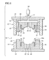
- FIGS 1 and 2 are sectional views showing an insert molding die (assembly) 10 in accordance with the embodiment of the invention.
- the insert molding die 10 includes a lower die 11 and an upper die 12 to be mated with each other.
- the lower die 11 is provided in the form of an immovable die
- the upper die 12 is provided in the form of a movable die.
- FIGS illustrate the molding die 10 in its opened state because the upper die 12 is being lifted up.
- a die (body) 15 is fixed on a holder plate 13 through an attachment plate 14.
- An inj ection cylinder 13 is provided on the top of the holder plate 13.
- a through hole 17 is formed so as topenetrate themin their plate-thickness (vertical) direction, communicating with a hot runner 18 formed in the attachment plate 14.
- the die 15 is provided, on both (left and right) sides thereof in the width direction and also at the center, with three injection gates 19, 20 and 21.
- the above through hole 17, the hot runner 18 and the gates 19, 20, 21 are communicated with each other.
- this molding die 10 is constructed so that molten resin (not shown) injected from the injection cylinder 16 flows through the through hole 17 and the hot runner 18 and successively fills up a cavity defined in the molding die 10.
- a pressure sensor 22 is embedded in the die 15 to detect a molding pressure of the molten resin filling up the cavity in the molding die 10.
- the lower part of the die 15 is formed to be concave and has projections 23 for abutment on a primary molded piece.
- the proj ections 23 abut to the primary molded piece 45 to support and retain the primary molded piece 45 on the proper position during injecting molten resin into the molding die 10.
- each of the upper-die pins 24 is provided, on the top end, with a brim part 25 of larger diameter. While, a body part 26 of smaller diameter is formed to extend from the brim part 25 downwardly.
- the die 15 is provided with a retainer hole 27 corresponding to the shape of the upper-die pin 24.
- the retainer hole 27 has a large diametrical part 28 on the upside and a small diametrical part 29 on the downside.
- the brim part 25 of the pin 24 is accommodated in the large diametrical part 28, while the body part 26 is accommodated in the small diametrical part 29.
- an urged spring 30 (as the upper-die urging means of the invention) is arranged above the brim part 25, while another urged spring 31 is arranged below the brim part 25.
- the upper spring 30 is adapted so as to press the upper-die pin 24 downwardly, while the lower spring 31 is adapted so as to lift up the pin 24.
- an urging force about the upper spring 30 is set larger than that about the lower spring 31, the upper-die pin 24 is depressed downwardly in a normal state.
- a die 35 is attached to a lower holder plate 33, as shown in Fig. 1. Similar to the upper die 12, the die 35 is also provided with projections 43, a pressure sensor 42 and a plurality of lower-die pins 44 as the lower-die pin members of the invention.
- the proj ections 43 abut to the primary molded piece 45 to support and retain the primary molded piece 45 on the proper position during injecting molten resin into the molding die 10.
- the lower-die pins 44 are positioned so as to oppose the upper-die pins 24 projecting from the die 15, respectively.
- Each of the lower-die pins 44 is formed to have a structure resulting from the upside-down arrangement of the upper-die pin 24. These pins 44 are urged upwardly by springs 30 (as the lower-die urging means of the invention). Additionally, the lower-die pin 44 is provided, at a tip thereof, with a locate pin 44a. The die 35 is provided, at its center, with a vent 36 for exhausting air being present in the cavity.
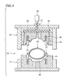
- a hollow primary molded piece 45 is arranged on the lower die 11 under condition of opening the molding die 10. Simultaneously, it is started to inject molten resin 46 from the injection cylinder 16.
- the primary molded piece 45 is a kind of core member to be used in molding an automotive cross car beam (not shown).
- the primary molded piece 45 is provided, on both sides along the longitudinal direction, with flanges 47.
- the primary molded piece 45 is mounted on the lower-die pins 44 while the flanges 47 are being arranged in position by the locate pins 44a. Consequently, the primary molded piece 45 is lifted up apart from a concave bottom surface 48 forming the cavity of the lower die 11.
- the molten resin 46 injected from the injection cylinder 16 reaches up to the hot runner 18 through the through hole 17.
- the upper die 12 is lowered to close the molding die 10. Then, although the upper-die pins 24 of the upper die 12 begin to press the flanges 47 of the primary molded piece 45 downwardly, it is positioned apart from an upper surface 49 of the concave part of the upper die 12 and also the above concave bottom surface 48 of the lower die 11 in predetermined distances respectively (each larger than a thickness of the resin 46 of the product after being molded). From this state, when the molten resin 46 is further injected from the injection cylinder 16 as shown in Figs. 8 and 9, the molten resin 46 begins to fill up the cavity 50 by way of the hot runner 18 and the gates 19, 20, and 21.
- the molding die 10 is closed up completely to make the upper die 12 and the lower die 11 pressurize the primary molded piece 45 and the molten resin 46 thereabout.
- the underside of the primary molded piece 45 has been already filled up with the molten resin 46, there is no possibility that the primary molded piece 45 is collapsed or deflected in spite of further application of pressure to the piece 45.
- the molten resin 46 goes around the almost whole area in the cavity 50 of the molding die 10 equally, there is no possibility of occurrence of short shot.
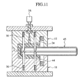
- a lower die 51 may be provided with an injection cylinder 56 and a feed hole 52 penetrating a die 55 and communicating with the cavity.
- the injection cylinder 56 for the lower die 51, it is possible to fill up the cavity with the molten resin 46 through both routes of an upper die 53 and the lower die 51.
- the molten resin goes around the underside of the primary molded piece sufficiently, it is possible to avoid an occurrence of defects, such as short shot.
- the upper-die pins 24 and the lower-die pins 44 are urged by the springs 30 in the above-mentioned embodiment, they may be replaced by any ones of pneumatic cylinders, pneumatic dampers and hydraulic cylinders.
- pneumatic cylinders or dampers it is possible to adjust the magnitudes of forces to urge the upper-die pins 24 and the lower-die pins 44 easily.
- hydraulic cylinders it is possible to accomplish the fine adjustment of the magnitudes of forces certainly and simply.
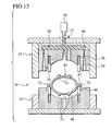
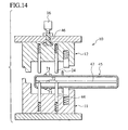
- Figs. 13 and 14 show a modification of the insert molding die which is shown in Figs. 4 and 5.
- projections 71 and 72 are provided instead of the projections 23 and 43.
- the projections 71 project from the hollow primary molded piece 45 toward the upper die 12 and the lower die 11 in the vertical direction.
- the projections 72 project from the hollow primary molded piece 45 in the horizontal direction.
- the projections 71 abut against the inner surface of the lower and upper dies 11 and 12 to support and retain the hollow primary molded piece 45 on the proper position in the vertical direction during injecting molten resin into the molding die 10.
- the projections 72 abut against the inner side surface of the lower and upper dies 11 and 12 to support and retain the hollow primary molded piece 45 on the proper position in the horizontal direction during injecting molten resin into the molding die 10.
- the hollow primary molded piece 45 carries proj ections 71 and 72, the rigidity of the hollow primary molded piece 45 is improved, so that the hollow primary molded piece 45 is prevented from being collapsed because of the pressure of the molten resin.
- the present invention may be applied to an injection compression molding or an injection press molding as well as the injection molding.
- the above-mentioned embodiment is exemplified by a vertical mold clamping form using the upper die and the lower die
- the present invention is not limited to only this clamping form.
- the above-mentioned structure of the molding die is applicable to a lateral mold clamping form. That is, needless to say, there is no restriction as for the moving direction of the upper and lower dies.
Landscapes
- Engineering & Computer Science (AREA)
- Manufacturing & Machinery (AREA)
- Mechanical Engineering (AREA)
- Moulds For Moulding Plastics Or The Like (AREA)
- Injection Moulding Of Plastics Or The Like (AREA)
Applications Claiming Priority (2)
| Application Number | Priority Date | Filing Date | Title |
|---|---|---|---|
| JP2003063767A JP4252337B2 (ja) | 2003-03-10 | 2003-03-10 | 中空部品のインサート成形用金型 |
| JP2003063767 | 2003-03-10 |
Publications (2)
| Publication Number | Publication Date |
|---|---|
| EP1457302A1 true EP1457302A1 (fr) | 2004-09-15 |
| EP1457302B1 EP1457302B1 (fr) | 2009-04-29 |
Family
ID=32767898
Family Applications (1)
| Application Number | Title | Priority Date | Filing Date |
|---|---|---|---|
| EP04005597A Expired - Lifetime EP1457302B1 (fr) | 2003-03-10 | 2004-03-09 | Moule pour surmoulage et procédé de moulage d'une pièce creuse |
Country Status (4)
| Country | Link |
|---|---|
| US (1) | US7396222B2 (fr) |
| EP (1) | EP1457302B1 (fr) |
| JP (1) | JP4252337B2 (fr) |
| DE (1) | DE602004020825D1 (fr) |
Cited By (10)
| Publication number | Priority date | Publication date | Assignee | Title |
|---|---|---|---|---|
| WO2008010600A1 (fr) * | 2006-07-19 | 2008-01-24 | Du Pont-Mitsui Polychemicals Co., Ltd. | Procédé de fabrication d'un corps creux en résine synthétique |
| DE102006045411A1 (de) * | 2006-09-26 | 2008-03-27 | Webasto Ag | Werkzeug zum Umschäumen und/oder Umspritzen eines im Wesentlichen plattenförmigen Werkstücks |
| WO2010089628A1 (fr) * | 2009-02-08 | 2010-08-12 | Sony Ericsson Mobile Communications Ab | Téléphone portable monobloc moulé par injection, machine et procédé |
| US8430258B2 (en) | 2006-07-19 | 2013-04-30 | Du Pont-Mitsui Poluchemicals Co., Ltd. | Synthetic resin hollow body |
| US8517197B2 (en) | 2006-07-19 | 2013-08-27 | Du Pont-Mitsui Polychemicals Co., Ltd. | Synthetic resin hollow body |
| WO2013187529A1 (fr) * | 2012-06-13 | 2013-12-19 | Yazaki Corporation | Procédé de moulage en résine, moule métallique pour un moulage en résine, et raccord de borne |
| CN103552200A (zh) * | 2013-10-23 | 2014-02-05 | 苏州泽汉汽车零部件有限公司 | 汽车epp方向盘模具及汽车方向盘 |
| EP2556938A3 (fr) * | 2011-08-09 | 2017-01-18 | Dongshin Industry Inc. | Moule de formation de mousse EPP de volant de direction pour véhicule |
| US20170129141A1 (en) * | 2014-06-24 | 2017-05-11 | Nok Corporation | Insert molding die structure |
| EP4394897A1 (fr) * | 2022-12-30 | 2024-07-03 | Sono Motors GmbH | Procédé et dispositif de fabrication d'un panneau photovoltaïque doté d'une structure de support moulée par préfixation dans un dispositif de moulage |
Families Citing this family (27)
| Publication number | Priority date | Publication date | Assignee | Title |
|---|---|---|---|---|
| WO2006099673A1 (fr) * | 2005-03-23 | 2006-09-28 | Confoil Pty Ltd | Appareil et procede pour separer des contenants differents orientes verticalement |
| DE102005059375A1 (de) * | 2005-12-09 | 2007-06-14 | Biotronik Crm Patent Ag | Vorrichtung und Verfahren zur Herstellung von Elektroden für Batterien |
| JP2010234641A (ja) * | 2009-03-31 | 2010-10-21 | Honda Motor Co Ltd | インサート成形方法及び装置 |
| KR100913949B1 (ko) * | 2009-04-14 | 2009-08-25 | 박제현 | 투명 스탠드넥 성형 방법 |
| KR100913950B1 (ko) * | 2009-04-14 | 2009-08-25 | 박제현 | 이중 컬러를 갖는 스탠드넥 성형 방법 |
| JP5363229B2 (ja) * | 2009-07-27 | 2013-12-11 | タイガースポリマー株式会社 | 射出成形方法 |
| US20120076888A1 (en) * | 2010-09-28 | 2012-03-29 | Cheng Uei Precision Industry Co., Ltd. | Mould with the contact prepressing and positioning function |
| US8512619B2 (en) * | 2010-12-06 | 2013-08-20 | Nike, Inc. | Methods for manufacturing a golf ball |
| JP5619643B2 (ja) | 2011-02-01 | 2014-11-05 | 小島プレス工業株式会社 | ダイレクト成形機 |
| US8974224B2 (en) | 2011-03-08 | 2015-03-10 | Craig M. Stanley | Position-locking apparatus for insert and over molding of delicate components |
| DE102012100760B4 (de) * | 2012-01-31 | 2022-09-29 | Gerresheimer Regensburg Gmbh | Vorrichtung zum Anspritzen eines Kunststoffansatzelementes und Vertikalspritzgießmaschine |
| JP5661087B2 (ja) | 2012-11-30 | 2015-01-28 | 東海興業株式会社 | インサート成形品、インサート成形方法、及びインサート成形装置 |
| DE102013204564A1 (de) * | 2013-03-15 | 2014-09-18 | Rti Sports Vertrieb Von Sportartikeln Gmbh | Spritzgussform für einen Fahrradgriff, Verfahren zur Herstellung eines Fahrradgriffs sowie Fahrradgriff |
| US9616603B2 (en) * | 2013-05-06 | 2017-04-11 | Google Technology Holdings LLC | Floating core for glass insert molding method and apparatuses therefrom |
| US9586351B2 (en) | 2013-05-06 | 2017-03-07 | Google Technology Holdings LLC | Floating core for glass insert molding method and apparatuses therefrom |
| US9023267B2 (en) * | 2013-05-20 | 2015-05-05 | Google Technology Holdings LLC | Floating core for glass insert molding method and apparatuses therefrom |
| US20150224685A1 (en) * | 2014-02-13 | 2015-08-13 | Caterpillar Inc. | System and method for manufacturing an article |
| JP6865926B2 (ja) * | 2016-11-28 | 2021-04-28 | 株式会社テクノクラーツ | 成形金型の突出し機構、該突出し機構を備える成形金型 |
| IT201700105306A1 (it) * | 2017-09-20 | 2019-03-20 | Inglass Spa | Procedimento e apparecchiatura per la produzione di articoli cavi di materia plastica stampata ad iniezione |
| JP7229741B2 (ja) * | 2018-12-06 | 2023-02-28 | 三菱重工業株式会社 | 複合材構造体の製造装置並びに複合材構造体の製造方法 |
| US11504890B2 (en) * | 2019-05-27 | 2022-11-22 | Hyundai Motor Company | Insert molding apparatus |
| CN111148616B (zh) * | 2019-12-16 | 2022-03-08 | 苏州信运比尔精密机械有限公司 | 用于工件一体式成型设备 |
| CN113631346B (zh) | 2020-03-05 | 2023-04-07 | 谷歌有限责任公司 | 零或低拔模角注射模制方法和系统 |
| US11659645B2 (en) | 2021-06-01 | 2023-05-23 | Moxtek, Inc. | Monolithic x-ray source housing |
| US11840002B1 (en) * | 2022-10-27 | 2023-12-12 | Cool Things Corp. | Donut tooling mold structure and method |
| WO2024187417A1 (fr) * | 2023-03-15 | 2024-09-19 | HELLA GmbH & Co. KGaA | Outil de moulage par injection surmoulant un élément d'insert et méthode de surmoulage d'un élément d'insert |
| DE102023110984A1 (de) | 2023-04-27 | 2024-10-31 | Igus Gmbh | Kunststoff-Spritzgussverfahren zur Herstellung von Hohlkörpern |
Citations (9)
| Publication number | Priority date | Publication date | Assignee | Title |
|---|---|---|---|---|
| JPS5396061A (en) * | 1977-02-02 | 1978-08-22 | Nok Corp | Method of coating metal article with rubber or resin material |
| JPS61234536A (ja) * | 1985-04-11 | 1986-10-18 | Nec Corp | 樹脂封止金型 |
| JPH01275024A (ja) * | 1988-04-27 | 1989-11-02 | Kinugawa Rubber Ind Co Ltd | プロテクタ付きホースの製造方法 |
| EP0472199A1 (fr) * | 1990-08-22 | 1992-02-26 | Kabushiki Kaisha Toshiba | Procédé de fabrication d'un dispositif semi-conducteur moulé dans du plastique et appareillage pour sa fabrication |
| JPH0584770A (ja) * | 1991-03-08 | 1993-04-06 | Toyoda Gosei Co Ltd | 合成樹脂成形品の製造方法 |
| US5356576A (en) * | 1991-03-26 | 1994-10-18 | Mannesmann Aktiengesellschaft | Process for the manufacture of plastic moldings with decorative coating |
| JPH106348A (ja) * | 1996-06-21 | 1998-01-13 | Calsonic Corp | 中空中子及びその製造方法並びに中空中子を用いた中空樹脂製品の製造方法 |
| JPH1086180A (ja) * | 1996-09-19 | 1998-04-07 | Hirotoshi Nishida | 樹脂封止成形品の射出成形方法及び射出成形金型 |
| JPH11333882A (ja) * | 1998-05-27 | 1999-12-07 | Miyazaki Oki Electric Co Ltd | 半導体装置の樹脂封止用金型 |
Family Cites Families (4)
| Publication number | Priority date | Publication date | Assignee | Title |
|---|---|---|---|---|
| JP3219407B2 (ja) | 1990-11-26 | 2001-10-15 | エクセル株式会社 | 多層プラスチック管及びその製造方法 |
| JP3636259B2 (ja) | 1996-12-17 | 2005-04-06 | ブリヂストンスポーツ株式会社 | ゴルフボール成形金型 |
| JPH10258442A (ja) | 1997-03-21 | 1998-09-29 | Aisan Ind Co Ltd | インサート成形品の射出成形方法 |
| JP2000208232A (ja) * | 1999-01-11 | 2000-07-28 | D D K Ltd | ハ―ネス製造方法及びその方法に使用する金型 |
-
2003
- 2003-03-10 JP JP2003063767A patent/JP4252337B2/ja not_active Expired - Fee Related
-
2004
- 2004-03-09 DE DE602004020825T patent/DE602004020825D1/de not_active Expired - Fee Related
- 2004-03-09 EP EP04005597A patent/EP1457302B1/fr not_active Expired - Lifetime
- 2004-03-10 US US10/797,641 patent/US7396222B2/en not_active Expired - Fee Related
Patent Citations (9)
| Publication number | Priority date | Publication date | Assignee | Title |
|---|---|---|---|---|
| JPS5396061A (en) * | 1977-02-02 | 1978-08-22 | Nok Corp | Method of coating metal article with rubber or resin material |
| JPS61234536A (ja) * | 1985-04-11 | 1986-10-18 | Nec Corp | 樹脂封止金型 |
| JPH01275024A (ja) * | 1988-04-27 | 1989-11-02 | Kinugawa Rubber Ind Co Ltd | プロテクタ付きホースの製造方法 |
| EP0472199A1 (fr) * | 1990-08-22 | 1992-02-26 | Kabushiki Kaisha Toshiba | Procédé de fabrication d'un dispositif semi-conducteur moulé dans du plastique et appareillage pour sa fabrication |
| JPH0584770A (ja) * | 1991-03-08 | 1993-04-06 | Toyoda Gosei Co Ltd | 合成樹脂成形品の製造方法 |
| US5356576A (en) * | 1991-03-26 | 1994-10-18 | Mannesmann Aktiengesellschaft | Process for the manufacture of plastic moldings with decorative coating |
| JPH106348A (ja) * | 1996-06-21 | 1998-01-13 | Calsonic Corp | 中空中子及びその製造方法並びに中空中子を用いた中空樹脂製品の製造方法 |
| JPH1086180A (ja) * | 1996-09-19 | 1998-04-07 | Hirotoshi Nishida | 樹脂封止成形品の射出成形方法及び射出成形金型 |
| JPH11333882A (ja) * | 1998-05-27 | 1999-12-07 | Miyazaki Oki Electric Co Ltd | 半導体装置の樹脂封止用金型 |
Non-Patent Citations (7)
| Title |
|---|
| PATENT ABSTRACTS OF JAPAN vol. 002, no. 131 (C - 026) 31 October 1978 (1978-10-31) * |
| PATENT ABSTRACTS OF JAPAN vol. 011, no. 081 (E - 488) 12 March 1987 (1987-03-12) * |
| PATENT ABSTRACTS OF JAPAN vol. 014, no. 046 (M - 0926) 26 January 1990 (1990-01-26) * |
| PATENT ABSTRACTS OF JAPAN vol. 017, no. 410 (M - 1455) 30 July 1993 (1993-07-30) * |
| PATENT ABSTRACTS OF JAPAN vol. 1998, no. 05 30 April 1998 (1998-04-30) * |
| PATENT ABSTRACTS OF JAPAN vol. 1998, no. 09 31 July 1998 (1998-07-31) * |
| PATENT ABSTRACTS OF JAPAN vol. 2000, no. 03 30 March 2000 (2000-03-30) * |
Cited By (21)
| Publication number | Priority date | Publication date | Assignee | Title |
|---|---|---|---|---|
| US8517197B2 (en) | 2006-07-19 | 2013-08-27 | Du Pont-Mitsui Polychemicals Co., Ltd. | Synthetic resin hollow body |
| WO2008010600A1 (fr) * | 2006-07-19 | 2008-01-24 | Du Pont-Mitsui Polychemicals Co., Ltd. | Procédé de fabrication d'un corps creux en résine synthétique |
| KR100955337B1 (ko) * | 2006-07-19 | 2010-04-29 | 듀폰-미츠이 폴리케미칼 가부시키가이샤 | 합성 수지 중공체의 제조 방법 |
| US7988897B2 (en) | 2006-07-19 | 2011-08-02 | Du Pont-Mitsui Polychemicals Co., Ltd. | Manufacturing method of synthetic resin hollow body |
| CN101489754B (zh) * | 2006-07-19 | 2012-01-11 | 三井-杜邦聚合化学株式会社 | 合成树脂中空体的制造方法 |
| CN102357980A (zh) * | 2006-07-19 | 2012-02-22 | 三井-杜邦聚合化学株式会社 | 合成树脂中空体的制造方法 |
| US8430258B2 (en) | 2006-07-19 | 2013-04-30 | Du Pont-Mitsui Poluchemicals Co., Ltd. | Synthetic resin hollow body |
| DE102006045411B4 (de) * | 2006-09-26 | 2008-11-13 | Webasto Ag | Werkzeug zum Umschäumen und/oder Umspritzen eines im Wesentlichen plattenförmigen Werkstücks |
| DE102006045411A1 (de) * | 2006-09-26 | 2008-03-27 | Webasto Ag | Werkzeug zum Umschäumen und/oder Umspritzen eines im Wesentlichen plattenförmigen Werkstücks |
| WO2010089628A1 (fr) * | 2009-02-08 | 2010-08-12 | Sony Ericsson Mobile Communications Ab | Téléphone portable monobloc moulé par injection, machine et procédé |
| US8180411B2 (en) | 2009-02-08 | 2012-05-15 | Sony Ericsson Mobile Communications Ab | Injection molded solid mobile phone, machine, and method |
| EP2556938A3 (fr) * | 2011-08-09 | 2017-01-18 | Dongshin Industry Inc. | Moule de formation de mousse EPP de volant de direction pour véhicule |
| WO2013187529A1 (fr) * | 2012-06-13 | 2013-12-19 | Yazaki Corporation | Procédé de moulage en résine, moule métallique pour un moulage en résine, et raccord de borne |
| CN104412453A (zh) * | 2012-06-13 | 2015-03-11 | 矢崎总业株式会社 | 树脂成型方法、用于树脂成型的金属模具和端子配件 |
| CN104412453B (zh) * | 2012-06-13 | 2017-09-12 | 矢崎总业株式会社 | 树脂成型方法、用于树脂成型的金属模具和端子配件 |
| CN103552200A (zh) * | 2013-10-23 | 2014-02-05 | 苏州泽汉汽车零部件有限公司 | 汽车epp方向盘模具及汽车方向盘 |
| CN103552200B (zh) * | 2013-10-23 | 2017-02-15 | 苏州泽汉汽车零部件有限公司 | 汽车epp方向盘模具及汽车方向盘 |
| US20170129141A1 (en) * | 2014-06-24 | 2017-05-11 | Nok Corporation | Insert molding die structure |
| US10780610B2 (en) * | 2014-06-24 | 2020-09-22 | Nok Corporation | Insert molding die structure |
| EP4394897A1 (fr) * | 2022-12-30 | 2024-07-03 | Sono Motors GmbH | Procédé et dispositif de fabrication d'un panneau photovoltaïque doté d'une structure de support moulée par préfixation dans un dispositif de moulage |
| WO2024141316A1 (fr) * | 2022-12-30 | 2024-07-04 | Sono Motors Gmbh | Procédé et dispositif de production d'un panneau photovoltaïque avec une structure de support moulée par pré-fixation dans un dispositif de moulage |
Also Published As
| Publication number | Publication date |
|---|---|
| JP4252337B2 (ja) | 2009-04-08 |
| US7396222B2 (en) | 2008-07-08 |
| JP2004268456A (ja) | 2004-09-30 |
| US20040227272A1 (en) | 2004-11-18 |
| EP1457302B1 (fr) | 2009-04-29 |
| DE602004020825D1 (de) | 2009-06-10 |
Similar Documents
| Publication | Publication Date | Title |
|---|---|---|
| US7396222B2 (en) | Insert molding die and method for molding hollow component | |
| US5472334A (en) | Injection molding die for injection-molding base boards | |
| US8091611B2 (en) | Casting die device | |
| JP3732832B2 (ja) | 合成樹脂製中空体の射出成形方法および成形用金型 | |
| US6365083B1 (en) | Method of forming molded product from three or more semi-molded products and mold assembly therefor | |
| JP5973341B2 (ja) | 車両用アンダーカバーの製造方法 | |
| JP2007055148A (ja) | 射出成形用金型装置及び射出成形方法 | |
| US11400629B2 (en) | Injection molding die | |
| WO2007074667A1 (fr) | Moule de métal pour article profilé | |
| JP2014151639A (ja) | 樹脂製品の製造装置及び製造方法 | |
| JP7431087B2 (ja) | 多色成形品の製造方法、及び金型 | |
| CN209257380U (zh) | 一种用于制造车用音箱盖板的模具 | |
| JPH09201841A (ja) | 射出成形部品およびその製造方法 | |
| JP4812033B2 (ja) | 複合成形品の成形方法および成形用金型 | |
| JP5207623B2 (ja) | 成形装置 | |
| JPH081716A (ja) | 中空成形品の成形方法及びそれに用いられる金型 | |
| JP7190921B2 (ja) | 射出成形品の製造方法、及び射出成形金型 | |
| JP7455636B2 (ja) | 多色成形品、及び多色成形品の製造方法 | |
| KR101924029B1 (ko) | 다이캐스팅 금형 | |
| JP2009196166A (ja) | 樹脂成形品の成形方法並びに成形金型 | |
| JP3079519B2 (ja) | 射出成形用金型のバルブゲート装置 | |
| US20220227032A1 (en) | Injection mold | |
| KR20190105747A (ko) | 디프로스터 노즐 일체형 크래시 패드 및 이를 제조하기 위한 금형 장치 | |
| CN113320097A (zh) | 注塑成型用模具 | |
| JPH1199530A (ja) | 合成樹脂圧縮成形装置及び成形方法 |
Legal Events
| Date | Code | Title | Description |
|---|---|---|---|
| PUAI | Public reference made under article 153(3) epc to a published international application that has entered the european phase |
Free format text: ORIGINAL CODE: 0009012 |
|
| AK | Designated contracting states |
Kind code of ref document: A1 Designated state(s): AT BE BG CH CY CZ DE DK EE ES FI FR GB GR HU IE IT LI LU MC NL PL PT RO SE SI SK TR |
|
| AX | Request for extension of the european patent |
Extension state: AL LT LV MK |
|
| 17P | Request for examination filed |
Effective date: 20050107 |
|
| 17Q | First examination report despatched |
Effective date: 20050208 |
|
| AKX | Designation fees paid |
Designated state(s): DE FR GB |
|
| RTI1 | Title (correction) |
Free format text: INSERT MOLDING DIE AND METHOD FOR MOLDING A HOLLOW COMPONENT |
|
| GRAP | Despatch of communication of intention to grant a patent |
Free format text: ORIGINAL CODE: EPIDOSNIGR1 |
|
| GRAS | Grant fee paid |
Free format text: ORIGINAL CODE: EPIDOSNIGR3 |
|
| GRAA | (expected) grant |
Free format text: ORIGINAL CODE: 0009210 |
|
| AK | Designated contracting states |
Kind code of ref document: B1 Designated state(s): DE FR GB |
|
| REG | Reference to a national code |
Ref country code: GB Ref legal event code: FG4D |
|
| REF | Corresponds to: |
Ref document number: 602004020825 Country of ref document: DE Date of ref document: 20090610 Kind code of ref document: P |
|
| PLBE | No opposition filed within time limit |
Free format text: ORIGINAL CODE: 0009261 |
|
| STAA | Information on the status of an ep patent application or granted ep patent |
Free format text: STATUS: NO OPPOSITION FILED WITHIN TIME LIMIT |
|
| 26N | No opposition filed |
Effective date: 20100201 |
|
| GBPC | Gb: european patent ceased through non-payment of renewal fee |
Effective date: 20100309 |
|
| REG | Reference to a national code |
Ref country code: FR Ref legal event code: ST Effective date: 20101130 |
|
| PG25 | Lapsed in a contracting state [announced via postgrant information from national office to epo] |
Ref country code: FR Free format text: LAPSE BECAUSE OF NON-PAYMENT OF DUE FEES Effective date: 20100331 |
|
| PG25 | Lapsed in a contracting state [announced via postgrant information from national office to epo] |
Ref country code: DE Free format text: LAPSE BECAUSE OF NON-PAYMENT OF DUE FEES Effective date: 20101001 |
|
| PG25 | Lapsed in a contracting state [announced via postgrant information from national office to epo] |
Ref country code: GB Free format text: LAPSE BECAUSE OF NON-PAYMENT OF DUE FEES Effective date: 20100309 |