EP4394897A1 - Procédé et dispositif de fabrication d'un panneau photovoltaïque doté d'une structure de support moulée par préfixation dans un dispositif de moulage - Google Patents
Procédé et dispositif de fabrication d'un panneau photovoltaïque doté d'une structure de support moulée par préfixation dans un dispositif de moulage Download PDFInfo
- Publication number
- EP4394897A1 EP4394897A1 EP22217403.9A EP22217403A EP4394897A1 EP 4394897 A1 EP4394897 A1 EP 4394897A1 EP 22217403 A EP22217403 A EP 22217403A EP 4394897 A1 EP4394897 A1 EP 4394897A1
- Authority
- EP
- European Patent Office
- Prior art keywords
- label
- moulding
- arrangement
- core side
- photovoltaic
- Prior art date
- Legal status (The legal status is an assumption and is not a legal conclusion. Google has not performed a legal analysis and makes no representation as to the accuracy of the status listed.)
- Withdrawn
Links
Images


Classifications
-
- B—PERFORMING OPERATIONS; TRANSPORTING
- B29—WORKING OF PLASTICS; WORKING OF SUBSTANCES IN A PLASTIC STATE IN GENERAL
- B29C—SHAPING OR JOINING OF PLASTICS; SHAPING OF MATERIAL IN A PLASTIC STATE, NOT OTHERWISE PROVIDED FOR; AFTER-TREATMENT OF THE SHAPED PRODUCTS, e.g. REPAIRING
- B29C45/00—Injection moulding, i.e. forcing the required volume of moulding material through a nozzle into a closed mould; Apparatus therefor
- B29C45/14—Injection moulding, i.e. forcing the required volume of moulding material through a nozzle into a closed mould; Apparatus therefor incorporating preformed parts or layers, e.g. injection moulding around inserts or for coating articles
- B29C45/14065—Positioning or centering articles in the mould
-
- B—PERFORMING OPERATIONS; TRANSPORTING
- B29—WORKING OF PLASTICS; WORKING OF SUBSTANCES IN A PLASTIC STATE IN GENERAL
- B29C—SHAPING OR JOINING OF PLASTICS; SHAPING OF MATERIAL IN A PLASTIC STATE, NOT OTHERWISE PROVIDED FOR; AFTER-TREATMENT OF THE SHAPED PRODUCTS, e.g. REPAIRING
- B29C33/00—Moulds or cores; Details thereof or accessories therefor
- B29C33/12—Moulds or cores; Details thereof or accessories therefor with incorporated means for positioning inserts, e.g. labels
- B29C33/14—Moulds or cores; Details thereof or accessories therefor with incorporated means for positioning inserts, e.g. labels against the mould wall
- B29C33/18—Moulds or cores; Details thereof or accessories therefor with incorporated means for positioning inserts, e.g. labels against the mould wall using vacuum
-
- B—PERFORMING OPERATIONS; TRANSPORTING
- B29—WORKING OF PLASTICS; WORKING OF SUBSTANCES IN A PLASTIC STATE IN GENERAL
- B29C—SHAPING OR JOINING OF PLASTICS; SHAPING OF MATERIAL IN A PLASTIC STATE, NOT OTHERWISE PROVIDED FOR; AFTER-TREATMENT OF THE SHAPED PRODUCTS, e.g. REPAIRING
- B29C45/00—Injection moulding, i.e. forcing the required volume of moulding material through a nozzle into a closed mould; Apparatus therefor
- B29C45/14—Injection moulding, i.e. forcing the required volume of moulding material through a nozzle into a closed mould; Apparatus therefor incorporating preformed parts or layers, e.g. injection moulding around inserts or for coating articles
- B29C45/14065—Positioning or centering articles in the mould
- B29C45/14073—Positioning or centering articles in the mould using means being retractable during injection
-
- B—PERFORMING OPERATIONS; TRANSPORTING
- B29—WORKING OF PLASTICS; WORKING OF SUBSTANCES IN A PLASTIC STATE IN GENERAL
- B29C—SHAPING OR JOINING OF PLASTICS; SHAPING OF MATERIAL IN A PLASTIC STATE, NOT OTHERWISE PROVIDED FOR; AFTER-TREATMENT OF THE SHAPED PRODUCTS, e.g. REPAIRING
- B29C45/00—Injection moulding, i.e. forcing the required volume of moulding material through a nozzle into a closed mould; Apparatus therefor
- B29C45/14—Injection moulding, i.e. forcing the required volume of moulding material through a nozzle into a closed mould; Apparatus therefor incorporating preformed parts or layers, e.g. injection moulding around inserts or for coating articles
- B29C45/1418—Injection moulding, i.e. forcing the required volume of moulding material through a nozzle into a closed mould; Apparatus therefor incorporating preformed parts or layers, e.g. injection moulding around inserts or for coating articles the inserts being deformed or preformed, e.g. by the injection pressure
-
- B—PERFORMING OPERATIONS; TRANSPORTING
- B29—WORKING OF PLASTICS; WORKING OF SUBSTANCES IN A PLASTIC STATE IN GENERAL
- B29C—SHAPING OR JOINING OF PLASTICS; SHAPING OF MATERIAL IN A PLASTIC STATE, NOT OTHERWISE PROVIDED FOR; AFTER-TREATMENT OF THE SHAPED PRODUCTS, e.g. REPAIRING
- B29C45/00—Injection moulding, i.e. forcing the required volume of moulding material through a nozzle into a closed mould; Apparatus therefor
- B29C45/14—Injection moulding, i.e. forcing the required volume of moulding material through a nozzle into a closed mould; Apparatus therefor incorporating preformed parts or layers, e.g. injection moulding around inserts or for coating articles
- B29C45/14336—Coating a portion of the article, e.g. the edge of the article
-
- B—PERFORMING OPERATIONS; TRANSPORTING
- B29—WORKING OF PLASTICS; WORKING OF SUBSTANCES IN A PLASTIC STATE IN GENERAL
- B29C—SHAPING OR JOINING OF PLASTICS; SHAPING OF MATERIAL IN A PLASTIC STATE, NOT OTHERWISE PROVIDED FOR; AFTER-TREATMENT OF THE SHAPED PRODUCTS, e.g. REPAIRING
- B29C45/00—Injection moulding, i.e. forcing the required volume of moulding material through a nozzle into a closed mould; Apparatus therefor
- B29C45/14—Injection moulding, i.e. forcing the required volume of moulding material through a nozzle into a closed mould; Apparatus therefor incorporating preformed parts or layers, e.g. injection moulding around inserts or for coating articles
- B29C45/14778—Injection moulding, i.e. forcing the required volume of moulding material through a nozzle into a closed mould; Apparatus therefor incorporating preformed parts or layers, e.g. injection moulding around inserts or for coating articles the article consisting of a material with particular properties, e.g. porous, brittle
- B29C45/14811—Multilayered articles
-
- B—PERFORMING OPERATIONS; TRANSPORTING
- B29—WORKING OF PLASTICS; WORKING OF SUBSTANCES IN A PLASTIC STATE IN GENERAL
- B29C—SHAPING OR JOINING OF PLASTICS; SHAPING OF MATERIAL IN A PLASTIC STATE, NOT OTHERWISE PROVIDED FOR; AFTER-TREATMENT OF THE SHAPED PRODUCTS, e.g. REPAIRING
- B29C45/00—Injection moulding, i.e. forcing the required volume of moulding material through a nozzle into a closed mould; Apparatus therefor
- B29C45/17—Component parts, details or accessories; Auxiliary operations
- B29C45/46—Means for plasticising or homogenising the moulding material or forcing it into the mould
- B29C45/56—Means for plasticising or homogenising the moulding material or forcing it into the mould using mould parts movable during or after injection, e.g. injection-compression moulding
- B29C45/561—Injection-compression moulding
-
- H—ELECTRICITY
- H10—SEMICONDUCTOR DEVICES; ELECTRIC SOLID-STATE DEVICES NOT OTHERWISE PROVIDED FOR
- H10F—INORGANIC SEMICONDUCTOR DEVICES SENSITIVE TO INFRARED RADIATION, LIGHT, ELECTROMAGNETIC RADIATION OF SHORTER WAVELENGTH OR CORPUSCULAR RADIATION
- H10F19/00—Integrated devices, or assemblies of multiple devices, comprising at least one photovoltaic cell covered by group H10F10/00, e.g. photovoltaic modules
- H10F19/80—Encapsulations or containers for integrated devices, or assemblies of multiple devices, having photovoltaic cells
-
- B—PERFORMING OPERATIONS; TRANSPORTING
- B29—WORKING OF PLASTICS; WORKING OF SUBSTANCES IN A PLASTIC STATE IN GENERAL
- B29C—SHAPING OR JOINING OF PLASTICS; SHAPING OF MATERIAL IN A PLASTIC STATE, NOT OTHERWISE PROVIDED FOR; AFTER-TREATMENT OF THE SHAPED PRODUCTS, e.g. REPAIRING
- B29C45/00—Injection moulding, i.e. forcing the required volume of moulding material through a nozzle into a closed mould; Apparatus therefor
- B29C45/14—Injection moulding, i.e. forcing the required volume of moulding material through a nozzle into a closed mould; Apparatus therefor incorporating preformed parts or layers, e.g. injection moulding around inserts or for coating articles
- B29C45/14065—Positioning or centering articles in the mould
- B29C2045/14147—Positioning or centering articles in the mould using pins or needles penetrating through the insert
-
- B—PERFORMING OPERATIONS; TRANSPORTING
- B29—WORKING OF PLASTICS; WORKING OF SUBSTANCES IN A PLASTIC STATE IN GENERAL
- B29C—SHAPING OR JOINING OF PLASTICS; SHAPING OF MATERIAL IN A PLASTIC STATE, NOT OTHERWISE PROVIDED FOR; AFTER-TREATMENT OF THE SHAPED PRODUCTS, e.g. REPAIRING
- B29C45/00—Injection moulding, i.e. forcing the required volume of moulding material through a nozzle into a closed mould; Apparatus therefor
- B29C45/14—Injection moulding, i.e. forcing the required volume of moulding material through a nozzle into a closed mould; Apparatus therefor incorporating preformed parts or layers, e.g. injection moulding around inserts or for coating articles
- B29C45/14065—Positioning or centering articles in the mould
- B29C2045/14155—Positioning or centering articles in the mould using vacuum or suction
-
- B—PERFORMING OPERATIONS; TRANSPORTING
- B29—WORKING OF PLASTICS; WORKING OF SUBSTANCES IN A PLASTIC STATE IN GENERAL
- B29C—SHAPING OR JOINING OF PLASTICS; SHAPING OF MATERIAL IN A PLASTIC STATE, NOT OTHERWISE PROVIDED FOR; AFTER-TREATMENT OF THE SHAPED PRODUCTS, e.g. REPAIRING
- B29C45/00—Injection moulding, i.e. forcing the required volume of moulding material through a nozzle into a closed mould; Apparatus therefor
- B29C45/17—Component parts, details or accessories; Auxiliary operations
- B29C45/46—Means for plasticising or homogenising the moulding material or forcing it into the mould
- B29C45/56—Means for plasticising or homogenising the moulding material or forcing it into the mould using mould parts movable during or after injection, e.g. injection-compression moulding
- B29C45/561—Injection-compression moulding
- B29C2045/565—Closing of the mould during injection
-
- B—PERFORMING OPERATIONS; TRANSPORTING
- B29—WORKING OF PLASTICS; WORKING OF SUBSTANCES IN A PLASTIC STATE IN GENERAL
- B29L—INDEXING SCHEME ASSOCIATED WITH SUBCLASS B29C, RELATING TO PARTICULAR ARTICLES
- B29L2031/00—Other particular articles
- B29L2031/30—Vehicles, e.g. ships or aircraft, or body parts thereof
- B29L2031/3005—Body finishings
- B29L2031/3041—Trim panels
-
- Y—GENERAL TAGGING OF NEW TECHNOLOGICAL DEVELOPMENTS; GENERAL TAGGING OF CROSS-SECTIONAL TECHNOLOGIES SPANNING OVER SEVERAL SECTIONS OF THE IPC; TECHNICAL SUBJECTS COVERED BY FORMER USPC CROSS-REFERENCE ART COLLECTIONS [XRACs] AND DIGESTS
- Y02—TECHNOLOGIES OR APPLICATIONS FOR MITIGATION OR ADAPTATION AGAINST CLIMATE CHANGE
- Y02E—REDUCTION OF GREENHOUSE GAS [GHG] EMISSIONS, RELATED TO ENERGY GENERATION, TRANSMISSION OR DISTRIBUTION
- Y02E10/00—Energy generation through renewable energy sources
- Y02E10/50—Photovoltaic [PV] energy
Definitions
- the method and device described herein may be applied for producing a photovoltaic panel which may be used and/or be specifically configured for various application fields such as for installation at vehicles, on building roofs or at other structures.
- vehicle body panel may refer to a panel which may be included in a body of any kind of vehicles such as cars, trucks, busses, mobile homes, trains, ships, airplanes, etc.
- embodiments are described herein with reference to car body panels for simplicity of description.
- PV cells may also be referred to as solar cells.
- a body panel of a vehicle including an integrated PV module may be referred to herein as PV integrated car body panel.
- PV panels are typically produced by providing planar, rigid, wafer-based solar cells and then laminating these solar cells between a front side glass sheet and a rear side support structure such as another glass sheet or a metal sheet. Therein, the solar cells are interposed between thin lamination foils serving for both, tightly encapsulating the solar cells and mechanically interconnecting the stack including the front and rear side sheets with the interposed solar cell arrangement.
- PV panels are also referred to as PV modules and have typically a planar structure. These PV panels are well suited for installation on buildings or in solar farms. However, such planar PV panels are hardly suited for an integration into curved surfaces such as for example surfaces of body panels of a car or another vehicle.
- PV cells are provided at a body of a car for generating electricity to be supplied to the car.
- Such electricity may be used for example for charging batteries of an electric car.
- the panel or, specifically, the car body panel including the solar cell arrangement may be regarded as a PV module having a non-planar shape.
- the photovoltaic panel may be a vehicle body part or may be a photovoltaic panel for a building or the like.
- the inventive method comprises at least the following steps, preferably in the indicated order:
- the moulding device comprises:
- the 3D-shaped inner surface may have any desired shape, but preferably may be concave.
- thermoplastic polymer may exert an excessive pressure and/or local pressure peaks onto the solar cells in the PV label, thereby inducing a risk of solar cell breakage.
- such prefixing arrangement may comprise a vacuum or suction arrangement with a suction cup for generating an underpressure in a suction area. Due to such underpressure, the PV label may be sucked towards the concave inner surface and may thereby at least preliminarily be fixed adjacent to this concave inner surface.
- the PV label typically has a relatively high stiffness, i.e. a low bendability, it may be difficult to reliably draw the PV label into direct contact with the concave inner surface of the core side moulding half using such pre-fixation only.
- the PV label is then mechanically pushed towards the inner surface of the core side moulding half using a displaceable plunger of a pushing arrangement included in the moulding device.
- a pushing arrangement may be comprised e.g. at the cavity side moulding half and its plunger may be displaced towards the concave inner surface of the core side moulding half, thereby pushing and bending the PV label disposed between both moulding halves into a configuration in which the front surface of the PV label abuts to a recessed portion of the concave inner surface.
- the PV label is reliably pressed into and held at the recessed portion of the concave inner surface before starting the actual polymer injection procedure.
- the PV label and, particularly, its solar cell arrangement may be supported along a wide area by the inner surface of the core side moulding half upon being subjected to the high-pressure polymer injection. The risk of solar cell breakage may be reduced accordingly.
- PV-integrated (car body) panel comprising a solar cell arrangement with multiple PV cells which are prepared based on brittle semiconductor wafers such as crystalline silicon wafers.
- PV cells are relatively rigid, i.e. they may generally not be bent into small bending radii of e.g. less than their lateral dimensions.
- the solar cell arrangement is generally comprised in an encapsulation including a front side polymeric foil and a rear side polymeric foil into which the solar cells, electrical interconnections and possibly other components are embedded.
- the solar cell arrangement may be reinforced by one or more stabilisation foils for forming a PV label.
- the entire PV label may then have a thickness in a range of between 0.5 mm to 10 mm, typically between 0.5 mm to 5 mm or between 1 mm and 3 mm. Lateral dimensions of the PV label may range from about 0.1 m to 4 m, typically from 0.2 m to 2 m.
- the PV label may be flexible and bendable and may be formed into a curved contour being adapted e.g. to a shape of the intended car body panel.
- the solar cells comprised in the car body panel cover a substantial portion, i.e. for example more than 30%, preferably more than 50% or even more than 70%, of an outer surface of the car body panel.
- the PV label is generally stiff and hardly bendable since it comprises a reinforcement or support structure in order to provide a self-supporting PV pane.
- Such support structure typically has a higher mechanical stability than the PV label.
- Such higher mechanical stability may result, interalia, from larger geometrical dimensions such as a larger thickness compared to the thickness of the PV label and/or higher stiffness due to material properties of the polymer used.
- the support structure and the PV label are generally mechanically interconnected such that forces acting onto the PV label may be transmitted to the support structure and vice versa.
- the support structure shall be manufactured using a processable polymer via injection moulding, preferably an injection compression moulding technique.
- Such technique may be implemented with a moulding device in accordance to an embodiment of the second aspect of the invention.
- Such moulding device generally comprises two moulding halves which may be displaced relative to each other between an open state and a closed state.
- One moulding half is referred to as core side or moving moulding half, the other one as cavity or fixed side moulding half.
- the configuration, as described above, may also be implemented vice versa.
- the two moulding halves are arranged with a distance from each other, i.e. there is a gap between the moulding halves.
- the distance may be at least some centimetres or even several decimetres.
- the distance should be large enough to initially insert the PV label between the two moulding halves and, upon completion of the compression moulding procedure, remove the final PV panel from between the two moulding halves.
- the moulding halves may be displaced towards each other in order to come to the closed state.
- the moulding device may have an actuator arrangement including e.g. one or more electromotors, hydraulics, pneumatics, etc. with which one or both of the moulding halves may be displaced.
- the two moulding halves are in tight contact with each other at least along a rim of the moulding halves.
- Both moulding halves have surfaces directed to each other, these surfaces being enclosed by the rim and being therefore referred to herein as inner surfaces. These inner surfaces have a contour such that a cavity is enclosed between the opposing surfaces upon the moulding halves being in the closed state.
- At least one of such inner surfaces has a generally concave contour, i.e. the inner surface comprises at least one recessed portion being recessed relative to the circumferentially enclosing rim.
- the other one of the inner surfaces may have a generally 3D-shaped, for example, concave or convex or a planar contour.
- the inner surfaces are contoured such that the enclosed cavity generally has the intended form of the PV panel to be produced.
- the inner surfaces as well as the surfaces of the resulting PV panel may have a curved contour with curvatures being present in one or two directions.
- the moulding device comprises a fixation arrangement.
- This fixation arrangement is specifically configured for fixing the sheet-like photovoltaic label to the core side moulding half in a way such that the PV label abuts at least with a partial area of its front surface to at least a partial area of the inner surface of the core side moulding half.
- the rear side of the PV label is directed to the inner surface of the cavity side moulding half.
- at least partial areas of the rear side surface of the PV label are spaced apart from the inner surface of the cavity side moulding half via interposed portions of the cavity.
- the fixation arrangement shall be configured for fixing the PV label such that the PV label may withstand forces applied to it during the injection moulding procedure.
- the PV label shall be fixed in a reversible manner in order to enable simple removal of the final product, i.e. the final PV panel, from the moulding device after completion of the moulding procedure.
- the fixation arrangement shall be configured such as to enable fixing the PV label without damaging the fragile solar cells enclosed therein.
- the fixation arrangement comprises a pre-fixing arrangement as well as a pushing arrangement.
- the pre-fixing arrangement is arranged at the core side moulding half.
- the prefixing arrangement may be arranged at the cavity side moulding half and in this case, the PV label will be pre-fixed within the latter.
- the pre-fixing arrangement is arranged at or close to the inner surface of the core side moulding half. Accordingly, the pre-fixing arrangement may be used for fixing the sheet-like PV label adjacent to this concave inner surface at least in a preliminary phase at the beginning of the procedure for preparing the support structure, i.e. in a situation in which the moulding device is in its open state.
- the photovoltaic label may have a planar or only slightly curved shape.
- the photovoltaic label might not be in full contact with the inner surface of the core side moulding half. Possible details of embodiments of the pre-fixing arrangement will be described further below.
- the pushing arrangement may then be used for pushing the pre-fixed PV label further towards the concave inner surface of the core side moulding half.
- the pushing arrangement is preferably situated at or within the cavity side moulding half.
- a plunger of the pushing arrangement may be displaced between a retracted position and a projecting position. In the retracted position, the plunger is situated distant to the core side moulding half and, particularly, may not yet be in mechanical contact with the PV label arranged at the core side moulding half.
- In the projecting position at least a tip portion of the plunger forming a pressing surface is displaced towards the core side moulding half to such an extend such as to project into the recessed portion of the concave inner surface of the core side moulding half.
- the plunger pushes the PV label arranged at the core side moulding half into such recessed portion and, preferably, until the PV label is pressed against the concave inner surface at such recessed portion of the core side moulding half. Due to such pressing action, the PV label is reliably fixed to the core side moulding half in a configuration in which it abuts to the inner surface and is therefore supported by the inner surface of the core side moulding half.
- the moulding device comprises an injection arrangement.
- This injection arrangement is configured for injecting a viscous polymer mass into the cavity between the moulding halves.
- the injection arrangement shall inject the polymer mass towards the rear surface of the PV label being arranged between the moulding halves.
- the injection arrangement may comprise one or more nozzles and/or ducts arranged at one or more injection locations along the inner surface of the cavity side moulding half.
- the nozzles and/or ducts may be supplied with the polymer mass using one or more pumps, conveyors or similar devices, wherein the polymer mass may be stored for example in a polymer reservoir.
- the injection arrangement may include a heater arrangement for heating the polymer mass to an elevated temperature at and/or before its injection into the cavity.
- a support structure is prepared at a rear side of a PV label using an injection moulding procedure.
- the PV label is first arranged between the two moulding halves and is pre-fixed such as to be located adjacent to the concave inner surface of the core side moulding half using the prefixing arrangement, while the moulding device being in its open state.
- the PV label may be planar or slightly curved with a curved portion of the PV label extending into the recessed portion of the curved inner surface of the core side moulding half.
- the PV label is not yet strongly pressed against such inner surface.
- the pushing arrangement is used for pushing and thereby bending the PV label further into the recessed portion until the front surface of the PV label abuts to the concave inner surface at the recessed portion of the core side moulding half.
- the moulding device After having reached the fully closed state, the moulding device is kept in such state until the injected polymer mass is at least partly solidified.
- solidification may occur upon the polymer mass being a thermoplastic polymer and being cooled down below a plastification temperature.
- the polymer mass may in principle also be a thermosetting polymer and the solidification may occur upon e.g. chemical reactions progressing throughout the polymer.
- the polymer mass forms the support structure for the PV label and the moulding device may be opened again by pulling the moulding halves away from each other.
- the PV label with the support structure attached thereto may be removed from the moulding device and may form the PV panel as the final fabrication product.
- the polymer mass is injected at least partly before completely closing the moulding device to the closed state. Furthermore, upon closing the moulding device, the moving moulding half, in this embodiment, the core side moulding half, is pushed towards the fixed moulding half, in this embodiment, the cavity side moulding half so as to compress and thereby distribute the previously injected molten polymer mass along the rear surface of the photovoltaic label.
- Such polymer mass depot may then be distributed along the entire surface of the PV label upon the moulding halves being pushed towards each other when closing the moulding device, thereby successively reducing the volume of the cavity between the moulding halves.
- the compression injection moulding is a process that starts when the mould or moulding device is not completely closed. Due to this fact, the pressures inside the cavity are rather low compared to conventional injection moulding. This is especially beneficial for the solar cells comprised in the PV label with respect to breakage.
- the photovoltaic label is pre-fixed to the core side moulding half by generating a local underpressure at a suction area using a suction arrangement being included in the pre-fixing arrangement, the suction area forming a partial area of the concave inner surface of the core side moulding half.
- the PV label may be pre-fixed by bringing pins provided in the interior of either one of the moulding halves into engagement with respective holes provided in the PV label, thereby, suspending it within the respective moulding half.
- the pre-fixation of the PV label to the core side moulding half may be established using a suction arrangement.
- Such suction arrangement may selectively and temporarily generate a local underpressure, i.e. a partial vacuum, at a suction area.
- the underpressure may be generated e.g. with a suction pump.
- the local underpressure may be strong enough to pull and keep the PV label fixed relative to the suction arrangement.
- the PV label may be held in such fixed configuration by applying a pressure between 8 to 10 bars.
- the suction area is situated within the inner surface of the core side moulding half and forms a partial area thereof, such partial area having for example less than 5%, preferably less than 1% of the overall area of the inner surface.
- the suction area may be located at a portion of the inner surface of the core side moulding half which is covered by a portion of the PV label at which the solar cell arrangement is embedded in the PV label.
- the suction arrangement may be configured and arranged such that its suction area sucks the PV label at a location where solar cells are included in the PV label.
- the pre-fixation using the underpressure may be established in such preserving manner such as to avoid any excessive forces to be applied to the solar cell arrangement, thereby preventing any solar cell breakage.
- Pre-fixing the PV label using a local underpressure may be established with relatively simple technical means. Furthermore, a fixation force applied to the PV label may be controlled by precisely controlling the underpressure generated by the suction arrangement. Additionally, such fixation force may be applied homogeneously along the suction area, thereby preventing local force peaks.
- the suction arrangement comprises a suction cup having a rim which is displaceable between a relaxed configuration in which the rim protrudes beyond the inner surface of the core side moulding half and a pressed configuration in which the rim does not protrude beyond the inner surface of the core side moulding half.
- the underpressure may be locally generated at the suction area using a specific suction cup.
- a specific suction cup is specifically configured such that, when no underpressure is generated and the suction cup therefore being in a relaxed configuration, the rim of the suction cup extends beyond the inner surface of the core side moulding half. Accordingly, in such relaxed configuration, the PV label may easily reach the rim of the suction cup by being slightly pressed into the recessed portion at the inner surface of the core side moulding half. The PV label may then cover this rim tightly. Upon being covered in such manner, the underpressure may be generated within the suction cup. As a result of such applied underpressure, the suction cup may get into its pressed configuration in which, e.g.
- the rim no more protrudes beyond the inner surface of the core side moulding half but is e.g. substantially flush with such inner surface. Accordingly, the PV label being adhered to the suction cup due to the underpressure is pulled towards the inner surface such as to e.g. approach to or even slightly abut to the inner surface of the core side moulding half.
- the PV label may not only be prefixed at the core side moulding half with a single suction arrangement but with several suction arrangements provided at different locations at the inner surface of the core side moulding half.
- each suction arrangement may generate an underpressure at a local suction area associated to this suction arrangement.
- each suction arrangement may be implemented with at least one suction cup.
- the different suction arrangements may be located for example close to a periphery of the inner surface of the core side moulding half.
- at least one or more suction arrangements may be provided close to a centre of the inner surface of the core side moulding half.
- the pre-fixing arrangement may comprise two, three, four or even more suction arrangements. Using such multiplicity of suction arrangements, the PV label may be reliably held and pre-fixed at the core side moulding half.
- the pressure generated upon polymer injection would act along the entire rear surface of the PV label and, particularly, would also act in the partial area where the PV label is not stably supported by abutting to the inner surface of the core side moulding half but where the PV label abuts to the suction arrangements of the prefixing arrangement.
- a suction cup forming the suction arrangement may not stably support the PV label and, particularly, may not counteract any substantive injection forces.
- the PV label could suffer from local deformations upon being pressed towards and slightly into the flexible suction arrangement.
- Specifically configuring and arranging the plungers of the pushing arrangement such as to protect the PV label in the indicated partial areas may prevent such local deformations.
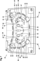
- the sheet-like PV label 3 has a thickness of about 2 mm to 4 mm and is supported at its rear side and at its circumference by the support structure 5 being made with a mouldable polymer material and having a thickness of typically about 1 mm to 5 mm.
- the thickness of the PV label 3 may slightly vary along its lateral extension, e.g. due to manufacturing tolerances, such variations typically being in a range of up to 20% relative to the mean thickness or up to 0.5 mm or even up to 1 mm absolute.
- the thickness of the support structure may vary along its lateral extension, e.g. due to different local mechanical requirements to be fulfilled by the support structure.
- a connection box 65 may be attached to the PV panel 1 at this exposed partial area 73.
Landscapes
- Engineering & Computer Science (AREA)
- Mechanical Engineering (AREA)
- Manufacturing & Machinery (AREA)
- Injection Moulding Of Plastics Or The Like (AREA)
Priority Applications (3)
| Application Number | Priority Date | Filing Date | Title |
|---|---|---|---|
| EP22217403.9A EP4394897A1 (fr) | 2022-12-30 | 2022-12-30 | Procédé et dispositif de fabrication d'un panneau photovoltaïque doté d'une structure de support moulée par préfixation dans un dispositif de moulage |
| EP23833772.9A EP4643397A1 (fr) | 2022-12-30 | 2023-12-18 | Procédé et dispositif de production d'un panneau photovoltaïque avec une structure de support moulée par pré-fixation dans un dispositif de moulage |
| PCT/EP2023/086435 WO2024141316A1 (fr) | 2022-12-30 | 2023-12-18 | Procédé et dispositif de production d'un panneau photovoltaïque avec une structure de support moulée par pré-fixation dans un dispositif de moulage |
Applications Claiming Priority (1)
| Application Number | Priority Date | Filing Date | Title |
|---|---|---|---|
| EP22217403.9A EP4394897A1 (fr) | 2022-12-30 | 2022-12-30 | Procédé et dispositif de fabrication d'un panneau photovoltaïque doté d'une structure de support moulée par préfixation dans un dispositif de moulage |
Publications (1)
| Publication Number | Publication Date |
|---|---|
| EP4394897A1 true EP4394897A1 (fr) | 2024-07-03 |
Family
ID=84766966
Family Applications (2)
| Application Number | Title | Priority Date | Filing Date |
|---|---|---|---|
| EP22217403.9A Withdrawn EP4394897A1 (fr) | 2022-12-30 | 2022-12-30 | Procédé et dispositif de fabrication d'un panneau photovoltaïque doté d'une structure de support moulée par préfixation dans un dispositif de moulage |
| EP23833772.9A Pending EP4643397A1 (fr) | 2022-12-30 | 2023-12-18 | Procédé et dispositif de production d'un panneau photovoltaïque avec une structure de support moulée par pré-fixation dans un dispositif de moulage |
Family Applications After (1)
| Application Number | Title | Priority Date | Filing Date |
|---|---|---|---|
| EP23833772.9A Pending EP4643397A1 (fr) | 2022-12-30 | 2023-12-18 | Procédé et dispositif de production d'un panneau photovoltaïque avec une structure de support moulée par pré-fixation dans un dispositif de moulage |
Country Status (2)
| Country | Link |
|---|---|
| EP (2) | EP4394897A1 (fr) |
| WO (1) | WO2024141316A1 (fr) |
Citations (17)
| Publication number | Priority date | Publication date | Assignee | Title |
|---|---|---|---|---|
| JPH05237882A (ja) * | 1992-02-28 | 1993-09-17 | Nissha Printing Co Ltd | 成形同時転写用金型 |
| JPH08267504A (ja) * | 1995-03-30 | 1996-10-15 | Nissha Printing Co Ltd | インサート成形品の製造方法とインサート成形金型 |
| JPH10309721A (ja) * | 1997-05-12 | 1998-11-24 | Honda Motor Co Ltd | シート付き樹脂成形品の製造装置およびその方法 |
| US6474976B1 (en) * | 1999-07-29 | 2002-11-05 | Kabushiki Kaisha Toyoda Jidoshokki Seisakusho | Film or sheet holding apparatus for an injection mold |
| EP1457302A1 (fr) * | 2003-03-10 | 2004-09-15 | Calsonic Kansei Corporation | Moule pour surmoulage et procédé de moulage d'une pièce creuse |
| DE102005055112A1 (de) * | 2005-11-18 | 2007-05-24 | Daimlerchrysler Ag | Fahrzeugaufbauteil |
| DE102007022964A1 (de) * | 2007-05-16 | 2008-11-20 | Webasto Ag | Bauteil mit Solargeneratorfunktion sowie Verfahren zur Herstellung eines solchen Bauteils |
| JP2013077708A (ja) * | 2011-09-30 | 2013-04-25 | Hitachi High-Technologies Corp | 太陽電池モジュールおよびその製造方法並びに太陽電池モジュールの製造装置 |
| EP3041131A1 (fr) * | 2014-11-16 | 2016-07-06 | Marek Adamczewski | Procédé de fabrication d'un élément de construction avec une cellule photovoltaïque et un tel élément avec ladite cellule |
| CN207224438U (zh) * | 2017-08-10 | 2018-04-13 | 鹰星精密工业(深圳)有限公司 | 一种模内吸气固定装置 |
| US20180178424A1 (en) * | 2016-12-23 | 2018-06-28 | Faurecia Innenraum Systeme Gmbh | Molding tool and method for forming and back-injecting a bendable sheet |
| WO2019020718A1 (fr) | 2017-07-26 | 2019-01-31 | Sono Motors Gmbh | Élément de carrosserie et procédé de fabrication d'un élément de carrosserie |
| WO2020187792A1 (fr) | 2019-03-20 | 2020-09-24 | Sono Motors Gmbh | Procédé de fabrication de module photovoltaïque |
| DE102020201465A1 (de) * | 2020-02-06 | 2021-08-12 | Elringklinger Ag | Solarmodul, Hybridbauteile, Formgebungswerkzeug und Verfahren zur Herstellung eines Hybridbauteils |
| WO2021260024A1 (fr) | 2020-06-24 | 2021-12-30 | Sono Motors Gmbh | Procédé de fabrication d'un module photovoltaïque incurvé comprenant un positionnement adapté de cellules photovoltaïques |
| WO2021260021A1 (fr) | 2020-06-24 | 2021-12-30 | Sono Motors Gmbh | Procédé de fabrication d'un module photovoltaïque comprenant la découpe au laser d'une étiquette photovoltaïque |
| WO2022122507A1 (fr) | 2020-12-11 | 2022-06-16 | Sono Motors Gmbh | Panneau de carrosserie de voiture comprenant un agencement de cellules solaires et son procédé de production |
Family Cites Families (2)
| Publication number | Priority date | Publication date | Assignee | Title |
|---|---|---|---|---|
| DE102022101935A1 (de) | 2022-01-27 | 2023-07-27 | Sono Motors Gmbh | Verfahren zur Herstellung eines photovoltaischen Panels, wie z.B. eines in die Fahrzeugkarosserie integrierten PV-Panels, unter Verwendung eines wärmehärtenden Polymers |
| DE102022108014A1 (de) | 2022-04-04 | 2023-10-05 | Sono Motors Gmbh | Verfahren zur Herstellung eines photovoltaischen Moduls durch In-Mould-Labeling mit spezifischem Temperaturmanagement |
-
2022
- 2022-12-30 EP EP22217403.9A patent/EP4394897A1/fr not_active Withdrawn
-
2023
- 2023-12-18 WO PCT/EP2023/086435 patent/WO2024141316A1/fr not_active Ceased
- 2023-12-18 EP EP23833772.9A patent/EP4643397A1/fr active Pending
Patent Citations (17)
| Publication number | Priority date | Publication date | Assignee | Title |
|---|---|---|---|---|
| JPH05237882A (ja) * | 1992-02-28 | 1993-09-17 | Nissha Printing Co Ltd | 成形同時転写用金型 |
| JPH08267504A (ja) * | 1995-03-30 | 1996-10-15 | Nissha Printing Co Ltd | インサート成形品の製造方法とインサート成形金型 |
| JPH10309721A (ja) * | 1997-05-12 | 1998-11-24 | Honda Motor Co Ltd | シート付き樹脂成形品の製造装置およびその方法 |
| US6474976B1 (en) * | 1999-07-29 | 2002-11-05 | Kabushiki Kaisha Toyoda Jidoshokki Seisakusho | Film or sheet holding apparatus for an injection mold |
| EP1457302A1 (fr) * | 2003-03-10 | 2004-09-15 | Calsonic Kansei Corporation | Moule pour surmoulage et procédé de moulage d'une pièce creuse |
| DE102005055112A1 (de) * | 2005-11-18 | 2007-05-24 | Daimlerchrysler Ag | Fahrzeugaufbauteil |
| DE102007022964A1 (de) * | 2007-05-16 | 2008-11-20 | Webasto Ag | Bauteil mit Solargeneratorfunktion sowie Verfahren zur Herstellung eines solchen Bauteils |
| JP2013077708A (ja) * | 2011-09-30 | 2013-04-25 | Hitachi High-Technologies Corp | 太陽電池モジュールおよびその製造方法並びに太陽電池モジュールの製造装置 |
| EP3041131A1 (fr) * | 2014-11-16 | 2016-07-06 | Marek Adamczewski | Procédé de fabrication d'un élément de construction avec une cellule photovoltaïque et un tel élément avec ladite cellule |
| US20180178424A1 (en) * | 2016-12-23 | 2018-06-28 | Faurecia Innenraum Systeme Gmbh | Molding tool and method for forming and back-injecting a bendable sheet |
| WO2019020718A1 (fr) | 2017-07-26 | 2019-01-31 | Sono Motors Gmbh | Élément de carrosserie et procédé de fabrication d'un élément de carrosserie |
| CN207224438U (zh) * | 2017-08-10 | 2018-04-13 | 鹰星精密工业(深圳)有限公司 | 一种模内吸气固定装置 |
| WO2020187792A1 (fr) | 2019-03-20 | 2020-09-24 | Sono Motors Gmbh | Procédé de fabrication de module photovoltaïque |
| DE102020201465A1 (de) * | 2020-02-06 | 2021-08-12 | Elringklinger Ag | Solarmodul, Hybridbauteile, Formgebungswerkzeug und Verfahren zur Herstellung eines Hybridbauteils |
| WO2021260024A1 (fr) | 2020-06-24 | 2021-12-30 | Sono Motors Gmbh | Procédé de fabrication d'un module photovoltaïque incurvé comprenant un positionnement adapté de cellules photovoltaïques |
| WO2021260021A1 (fr) | 2020-06-24 | 2021-12-30 | Sono Motors Gmbh | Procédé de fabrication d'un module photovoltaïque comprenant la découpe au laser d'une étiquette photovoltaïque |
| WO2022122507A1 (fr) | 2020-12-11 | 2022-06-16 | Sono Motors Gmbh | Panneau de carrosserie de voiture comprenant un agencement de cellules solaires et son procédé de production |
Also Published As
| Publication number | Publication date |
|---|---|
| EP4643397A1 (fr) | 2025-11-05 |
| WO2024141316A1 (fr) | 2024-07-04 |
Similar Documents
| Publication | Publication Date | Title |
|---|---|---|
| US10899077B2 (en) | Techniques for build platform part release in additive fabrication and related systems and methods | |
| CN113614927A (zh) | 一种用于制造光伏模块的方法 | |
| KR101249273B1 (ko) | 가요성 시트의 가장자리를 감싸는 개선된 방법 | |
| US20240047594A1 (en) | Car body panel including a solar cell arrangement and method for producing same | |
| EP2775536B1 (fr) | Panneau solaire et son procédé de fabrication | |
| EP2922676B1 (fr) | Pale de turbine éolienne avec protection contre la foudre | |
| CN102039675A (zh) | 固定装置 | |
| JP5914803B2 (ja) | インモールド成形方法、及びインモールド成形装置 | |
| DE102022101935A1 (de) | Verfahren zur Herstellung eines photovoltaischen Panels, wie z.B. eines in die Fahrzeugkarosserie integrierten PV-Panels, unter Verwendung eines wärmehärtenden Polymers | |
| EP4394897A1 (fr) | Procédé et dispositif de fabrication d'un panneau photovoltaïque doté d'une structure de support moulée par préfixation dans un dispositif de moulage | |
| WO2022099707A1 (fr) | Moule à noyau destiné à la production d'un élément de renforcement en forme de chapeau | |
| EP3720687A1 (fr) | Techniques de démoulage de partie de plateforme de construction en fabrication additive et systèmes et procédés associés | |
| EP4394896A1 (fr) | Procédé et dispositif de fabrication d'un panneau photovoltaïque comprenant un agencement de cellules solaires par moulage par injection-compression | |
| WO2024180145A1 (fr) | Procédé de production d'un panneau photovoltaïque tel qu'un panneau de carrosserie de véhicule intégré pv avec une structure de support arrière moulée et une structure de couvercle avant moulée directement revêtue | |
| CN114506095A (zh) | 一种用于制作帽型增强构件的芯模 | |
| CN103372951A (zh) | 用于将插入件定位在用于塑料材料的模具中的方法和设备 | |
| EP4394895A1 (fr) | Panneau sandwich photovoltaïque, en particulier panneau sandwich de revêtement de véhicule photovoltaïque, à structure arrière à cadre en nid d'abeilles et procédé de fabrication | |
| JP3916983B2 (ja) | プレフォームフィルムの製造方法 | |
| CN103042683B (zh) | 吸塑模具 | |
| WO2024133112A1 (fr) | Couvercle pour lit de charge ouvert de véhicule | |
| EP2596934B1 (fr) | Outil de moulage et procede de production de verre comprenant une moulure decorative en utilisant ledit outil | |
| TWI881656B (zh) | 用於製造風力渦輪機葉片之預製件元件的方法、預製件元件、葉片、風力渦輪機、上模具以及由上模具與下模具組成之模具裝置 | |
| CN213035176U (zh) | 系缆锚帽注塑模具 | |
| CN109483906B (zh) | 一种雷达天线罩结构的脱模方法 | |
| CN117382044A (zh) | 一种带金属嵌件的高强度天线罩一体成型模具及成型方法 |
Legal Events
| Date | Code | Title | Description |
|---|---|---|---|
| PUAI | Public reference made under article 153(3) epc to a published international application that has entered the european phase |
Free format text: ORIGINAL CODE: 0009012 |
|
| STAA | Information on the status of an ep patent application or granted ep patent |
Free format text: STATUS: THE APPLICATION HAS BEEN PUBLISHED |
|
| AK | Designated contracting states |
Kind code of ref document: A1 Designated state(s): AL AT BE BG CH CY CZ DE DK EE ES FI FR GB GR HR HU IE IS IT LI LT LU LV MC ME MK MT NL NO PL PT RO RS SE SI SK SM TR |
|
| STAA | Information on the status of an ep patent application or granted ep patent |
Free format text: STATUS: THE APPLICATION IS DEEMED TO BE WITHDRAWN |
|
| 18D | Application deemed to be withdrawn |
Effective date: 20250104 |