EP1457401A1 - Système de freinage d'un véhicule ferroviaire - Google Patents
Système de freinage d'un véhicule ferroviaire Download PDFInfo
- Publication number
- EP1457401A1 EP1457401A1 EP04002398A EP04002398A EP1457401A1 EP 1457401 A1 EP1457401 A1 EP 1457401A1 EP 04002398 A EP04002398 A EP 04002398A EP 04002398 A EP04002398 A EP 04002398A EP 1457401 A1 EP1457401 A1 EP 1457401A1
- Authority
- EP
- European Patent Office
- Prior art keywords
- piston
- braking device
- drive
- nut
- spindle
- Prior art date
- Legal status (The legal status is an assumption and is not a legal conclusion. Google has not performed a legal analysis and makes no representation as to the accuracy of the status listed.)
- Granted
Links
Images








Classifications
-
- B—PERFORMING OPERATIONS; TRANSPORTING
- B61—RAILWAYS
- B61H—BRAKES OR OTHER RETARDING DEVICES SPECIALLY ADAPTED FOR RAIL VEHICLES; ARRANGEMENT OR DISPOSITION THEREOF IN RAIL VEHICLES
- B61H13/00—Actuating rail-vehicle brakes
- B61H13/20—Transmitting mechanisms
- B61H13/24—Transmitting mechanisms for cars with two axles or bogies with two axles and braking cylinder(s) for each bogie, the mechanisms at each side being interconnected
-
- B—PERFORMING OPERATIONS; TRANSPORTING
- B61—RAILWAYS
- B61H—BRAKES OR OTHER RETARDING DEVICES SPECIALLY ADAPTED FOR RAIL VEHICLES; ARRANGEMENT OR DISPOSITION THEREOF IN RAIL VEHICLES
- B61H13/00—Actuating rail-vehicle brakes
- B61H13/02—Hand or other personal actuation
- B61H13/04—Hand or other personal actuation by mechanisms incorporating toothed gearing
Definitions
- the invention relates to a braking device of a rail vehicle, in particular one Freight car, comprising a parking brake device with a one by rotary actuating means initiated rotary movement in a linear application movement of at least one pressure-actuated cylinder-piston drive converting gear, according to the preamble of claim 1.
- Such a braking device is known for example from WO 00/02756 A1.
- the Parking brake device is inserted by turning a handwheel, the rotary movement via a coaxial to the handwheel and in the immediate vicinity of it arranged spindle drive is converted into a linear movement.
- This linear motion must be on a piston of the cylinder-piston drive located away from the handwheel and the spindle drive are transferred, its location and orientation on the bogie each may vary depending on the type and design of the rail vehicle.
- Flexible Power transmission elements such as pull ropes, flex ball trains or ball bearing, jacketed tension elements necessary to the linear movement in the respective position of the To deflect the cylinder piston drive and transfer it to the piston.
- the present invention is based on the object of a braking device of the type mentioned at the outset in such a way that they meet the aforementioned Avoids disadvantages. This object is solved by the features of claim 1.
- the power transmission path is due to the spatial Near gear wheel, spindle-nut drive and cylinder-piston drive short and directly. Because the superimposing forces of the service and parking brakes are directly in the cylinder piston drive can be supported, the power transmission elements upstream of this unit be dimensioned smaller.
- the gear mechanism and the nut-spindle drive are particularly preferred integrated in a housing of the cylinder-piston drive or with this into one Unit summarized, which on the one hand results in a very compact design and on the other hand, the gear transmission and the nut-spindle drive in front of locks Pollution are protected ..
- the rotary actuating means preferably comprise rotatable handwheels.
- the cardan shafts essentially in one plane are arranged perpendicular to a longitudinal extent of the rail vehicle, one results only small force deflection with low deflection losses.
- the gear transmission can be two by 180 Have gear inputs arranged offset from one another, which are immediate are connected in a rotationally fixed manner to the associated handwheel by means of a propeller shaft. Then the cardan shafts guide the rotary movements of the handwheels without intermediate switching other elements in the gear transmission.
- the gear transmission and the handwheels can be an intermediate gear for conversion the rotary movements brought about by the cardan shafts into a rotary movement at least one other, in connection with the transmission input of the gear transmission standing propeller shaft between, the intermediate gear such is formed that there are rotational movements in the same direction of the input-side drive shafts converts into a rotary movement of the output-side cardan shaft.
- the at least one cylinder piston drive extends in the essentially in the longitudinal direction of the rail vehicle.
- the gear train preferably formed by a bevel gear, for deflecting the rotary movement the propeller shaft or the propeller shafts in a rotational movement by one to the piston of the cylinder-piston drive parallel or coaxial axis.
- bevel gear transmissions compared to a worm gear that can also be used as a gear transmission higher efficiency and are for the present case by hand generated locking force is therefore very suitable.
- the bevel gear has, for example a bevel pinion rotatably connected to one end of a propeller shaft and one to it meshing bevel gear, with a nut of the nut spindle drive with the bevel gear of the bevel gearbox rotatably connected and a spindle of the mother spindle drive is attached to the piston.
- This can be done, for example, in that the Spindle of the mother-spindle drive can be coupled to the piston by means of a cone coupling and axially displaceable relative to the piston supported on a housing in a rotationally fixed manner, however is rotatably guided, for example by means of a polygonal profile.
- the at least one cylinder piston drive extends essentially perpendicular to the longitudinal direction of the rail vehicle.
- the gear transmission is preferably formed by a spur gear, which the Rotary movement passes parallel and on the output side an axially fixed and rotatable Drives sleeve in which the nut of the nut-spindle drive is axially displaceable and rotatable is stored. This results in a floating mounting of the mother spindle drive, so that it can shift axially to different things when parking Compensate for brake pad play on the right and left wheel.
- the spindle of the spindle nut drive on the pressure side of the piston of the one cylinder piston drive and the nut of the spindle nut drive on the pressure side of the piston of the other cylinder piston drive is designed to be attached.
- the spindle is on the piston of the one cylinder piston drive linearly displaceable and secured against rotation and the nut on the piston of the other cylinder piston drive linearly displaceable but freely rotatable, for example in that a guide for the spindle and for the nut within a central, cup-shaped shape is formed in the associated piston.
- the spindle and the nut are complementary to each end a bottom of the formations of the piston shaped stop body.
- the braking device is particularly preferred as being on a bogie by hanging brackets hanging brake module formed, each containing two a wheel axle with brake wheels assigned to two wheels and running parallel to them, which are connected to each other via push rods and carry brake blocks which by actuating the cylinder piston drives in brake engagement with assigned braking surfaces the wheels can be brought. Then preferably forms at least part of a brake beam directly the cylinders of the cylinder piston drives and the housing for the Gear transmission and for the mother spindle drive.
- the invention goes beyond that mentioned State of the art, in which the cylinder of the cylinder-piston drive is separate Component carried by the brake beam, which is also designed as a separate component becomes. Rather, according to the invention, the actually for holding the brake pads and brake beam intended to transmit the contact pressure also the cylinder of the cylinder piston drive or vice versa, so that fewer components compared to the prior art to be manufactured and assembled. Consequently, the invention makes it self-supporting Construction of the cylinder piston drives realized.
- a block brake device of a freight car designated, which on a bogie 2 of the freight car as a hanging brake module is set.
- the block brake device 1 includes a parking brake device 4 with a rotary movement initiated by rotary actuating means 6 into a linear movement a brake actuator of a pressure-operated cylinder piston drive 10 converting gear 12.
- the block brake device includes 1 two cylinder piston drives 10 with extending in the longitudinal direction of freight wagons Central axes 14, with both cylinder piston drives 10 at a transverse distance from one another are held at the ends of a brake beam 16.
- Actuate the cylinder piston drives 10 Brake blocks 20 of the block brake device 1 which are of no further interest here.
- the rotary actuation means comprise the parking brake device 4 on both sides of the vehicle, a rotatably mounted handwheel 6 with essentially the axis of rotation and the drive shafts arranged perpendicular to the longitudinal extent of the freight wagon 22 for transmitting the rotary movement initiated on the handwheels 6 in a transmission input 24 of the transmission 12.
- the handwheels 6 are on the bogie 2 by means of for reasons of clarity, bearings not shown rotatably mounted.
- a housing 26 of the cylinder piston drive 10 is integrated gear 12 and the handwheels 6 for example, an intermediate gear 28 held on the brake beam 16 for conversion of the rotational movements brought about by the input-side cardan shafts 22 Handwheels 6 in a rotary movement of an output side, with the transmission input 24 the transmission 12 in connection articulated shaft 30 interposed.
- This intermediate gear 28 is designed such that there are rotational movements in the same direction of the input side Cardan shafts 22 into a rotational movement of the output-side cardan shaft 30 implemented.
- the parking brake device 4 can be applied or released.
- the parking brake device 4 by turning one or both handwheels 6 clockwise tightened and released by turning it counterclockwise. But it can the parking brake devices 4 of both cylinder piston drives 10 are also actuated, if the intermediate gear 28 is designed as a differential transfer case.
- the cardan shafts 22 and in particular the output-side cardan shaft 30 of the intermediate gear 28 lie essentially in planes which are perpendicular to the central axis 14 of the Cylinder-piston drive 10 are arranged.
- the central axis 14 of the cylinder piston drive 10 a little bit downwards relative to the axes of rotation of the handwheels arranged. Consequently, a deflection of the rotary movements only takes place in these Levels instead.
- the cardan shafts 22, 30 preferably each have two joints.
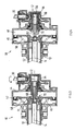
- the transmission 12 includes a Gear transmission preferably in the form of a bevel gear 32 for deflecting the Rotary movement of the drive shaft 30 on the output side with respect to the intermediate gear 28 in a rotational movement about a direction parallel to the actuation direction of the brake actuation member or coaxial axis, as shown in Fig.2.
- this is Axis formed by the central axis 14 of the cylinder piston drive 10.
- Intermediate gear 28 protrudes from the drive shaft 30 on the output side, forming a gear input perpendicular to the central axis 14 of the cylinder piston drive 10 into its housing 26 and carries a bevel pinion 34 of the bevel gear 32 which is non-rotatably connected to it, which with a bevel gear 36 of the bevel gearbox mounted coaxially to this central axis 14 32 combs.
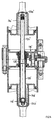
- the bevel gear 32 is in a housing part 38 of the housing 26 of the cylinder piston drive 10, which is axially connected to another, the brake cylinder 40 of the cylinder piston drive 10 containing cylinder housing part 42 is attached.
- One between a bottom 44 of the brake cylinder 40 and one in this coaxial Center axis 14 guided piston 46 formed pressure chamber 48 can via a in the cylinder housing part 42 trained connection 50 can be ventilated with compressed air.
- the axial force acting on the piston 46 is via a centered on the piston and on it Piston tube 51 held in a rotationally and axially fixed manner on an axially in a shoulder supported ring 53 and from this via a stimulation toothing 55 to a pressure nut 57 transmitted, which in turn via a self-locking thread with a Central axis 14 and in particular to the piston coaxial piston rod 52 is connected.
- the piston rod 52 protrudes out of the cylinder housing part on the side facing away from the transmission 12 42 out and is provided at the end with a yoke 54, via which the Brake pads 20 are operated. Furthermore, there is also one here in the cylinder housing part 42 wear adjuster 56 of no interest added.
- the piston 46 is supported a preferably conical coil spring 58 on a further base 60 of the cylinder housing part 42 from.
- the transmission 12 also includes a downstream of the bevel gear 32 the central axis 14 coaxial nut-spindle drive 62, of which a spindle nut 64 with the bevel gear 36 of the bevel gear 32 rotatably connected and one preferably provided with an axial through bore 66, forming a gear output spindle 68 can be supported on the piston 46 in the brake application direction.
- the support is preferably carried out due to a narrowing in the actuation or brake application device Cone coupling 70, the spindle 68 having a conical end, enlarged in diameter Mushroom 72, which in a complementary conical central recess 74 of the piston 46 is designed to be engageable.
- This is the gearbox output of the gear 12 forming spindle 68 that formed by the piston 46 Brake actuator of the cylinder piston drive 10 directly opposite.
- the spindle nut 64 is radial via a slide bearing 76 and axial via a needle bearing 78 in the housing 26 rotatably mounted.
- the spindle 68 of the nut spindle drive 62 is via thread means, preferably via a self-locking trapezoidal thread 80 over the Spindle nut 64 axially screwable.
- the spindle 68 is opposite Piston 46 axially displaceable, but guided non-rotatably.
- a rod 81 is pressed into a central bore in the piston 46 in a pressure-tight manner which is on a section 82 facing the nut spindle drive 62 with a External polygonal profile, for example, is provided with an external hexagonal profile, which into a complementary inner polygonal profile of the through hole 66 the spindle 68 engages.
- the piston 46 lies through the effect of the coil spring 58 on an axially projecting stop ring 84 on Bottom 44 of the cylinder housing part 42.
- FIG. 4 a situation is shown in which the service brake is applied Venting the pressure chamber 48 is actuated, the piston 46 against the action of Coil spring 58 was brought into the brake application position.
- Parking brake device 4 the spindle 68 is completely screwed into the spindle nut 64.
- the piston 46 of the mushroom 72 of the spindle 68 is then axial spaced and the section 82 of the rod 81 provided with the polygonal profile is a Extended part of the through bore 66 of the spindle 68, so that the cone coupling 70 is solved.
- the parking brake can be applied. This can be done on the basis of Fig.
- each formed by a propeller shaft 86 become.
- the two cardan shafts 86 are without an intermediate gear 28 directly connected to the associated handwheel 6 in a rotationally fixed manner, the drive shafts 86 again in a plane perpendicular to the central axis 14 of the cylinder piston drive 10 are arranged.
- each drive shaft 86 carries a bevel pinion 34 at the end the bevel gear 36 of the bevel gear 32 meshes.
- the gearbox and in particular the cylinder piston drive 10 as described in the previous embodiment educated.
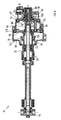
- the cylinder piston drive 10 comprises one Tandem cylinder with two pistons, of which a first piston 88 against the Spindle 68 of the spindle nut spindle unit 62 and a second piston 90 against the first Piston 88 can be supported axially and in particular in the brake application direction.
- housing 26 of the cylinder piston drive 10 is divided into three housing parts, by which is a housing part 38 pointing away from the yoke 54 of the piston rod 52, the bevel gear 32 and part of the nut-spindle drive 62, this housing part 38 axially adjoining first cylinder housing part 92, the first piston 88 and a second, the latter in turn axially adjoining cylinder housing part 94 the second piston 90 records.
- the first piston 88 is as described in the previous exemplary embodiments executed, in addition, it is provided with a piston tube pointing towards the second piston 90 96 provided which on the one hand between a bottom 98 of the second cylinder housing part 94 and a piston tube 100 of the second piston 90 engaging in it is sealingly led. Both pistons 88, 90 transmit the axial force acting on them to the Piston rod 52.
- the piston tube 96 of the first piston 88 is supported at the end on the second Piston 90, which in turn by preferably cylindrical coil springs 102 is supported on a further bottom 104 of the second cylinder housing part 94.
- Each between the bottoms 98, 106 of the two cylinder housing parts 92, 94 and the associated Piston 88, 90 is formed a pressure chamber 48, 108.
- the two pressure chambers 48, 108 are connected to one another via a plurality of hollow bolts 110 arranged with a circumferential spacing in connection, wherein the hollow pin 110 on the one hand in through holes of the Bottom 98 of the second cylinder housing part 94 slidably mounted and the other in for this purpose, coaxial through holes in the first piston 88 are pressed in in a pressure-tight manner.
- the most Housing 26 supported hollow bolt 110 also support in an advantageous dual function the first piston 88 in the circumferential direction when torque is applied to it by the spindle 68 is transmitted.
- FIG. 16 A further embodiment of a block brake device 1 'is shown in FIG.
- the Block brake device 1 ' is a whole on a bogie 2' shown in FIG. 16 Freight car attached hanging, which has two wheel sets 4 'with two wheels 6'.
- the block brake device 1 ' preferably comprises two by push rods 8' together connected brake beams 10 ', 12', four on the brake beams 10 ', 12' brake shoes 16 'held at the ends and carrying brake pads 14', four on the one hand on the Brake beam 10 ', 12' and on the other hand on the bogie 2 'articulated hanging brackets 18' and for example two in the brake bar 10 'formed as a hollow housing recorded brake actuators 20a ', 20b', not visible in FIG.
- the brake pads 14 ' a brake beam 10 ', 12' are assigned to the wheels 6 'of a wheel axle 22', the Brake beams 10 ', 12' run approximately parallel to the wheel axles 22 '.
- the two wheel sets 4 ' are resiliently mounted relative to the bogie 2' in a known manner. The suspension allows the two wheel sets 4 ', among other things, longitudinal and transverse movements can execute relative to the bogie 2.
- the push rods 8 ' By pressurizing cylinder-piston drives 20a ', 20b' of the brake actuators the push rods 8 'are actuated such that the brake beams 10', 12 'from each other moved away and thereby the brake pads 14 'carried by them against the wheels 6' in Brake application position are brought. 7 are the Push rods 8 'arranged substantially perpendicular to the brake beams 10', 12 '.
- the hanging tabs 18 ' are preferably pivotally mounted on the bogie 2'.
- a spherical block 24 ' is used as the pivot bearing, i.e. one inside a rubber sleeve 26 'with a complementary spherical bearing surface mounted ball head 28 'of a ball pin 30', as in the sectional view through a single hanging bracket 18 'according to FIG. 15 emerges.
- the ball pin 30 ' is preferably used as a flat pin two through holes 32 'at the ends, the flat bolt 30' preferably is received on a longitudinal beam, not shown, of the bogie 2 '.
- the All-round pivoting mounting of the hanging brackets 18 allows, on the one hand, that the brake beam 10 ', 12' together with the brake pads 14 'the transverse movements of the wheel sets 4' in Direction of the wheel axles 22 'can follow to ensure that they always the braking surfaces the wheels 6 'are opposite.
- the spherical block 24 ' enables pivoting the hanging tabs 18 'in the longitudinal or driving direction. Such a swivel movement takes place, for example, when the brake actuators 20a ', 20b' are actuated and Consequently, the wheel-side ends 34 'of the hanging tabs 18' transversely to the wheel axes 22 'from each other to move away or towards each other.
- the hanging tabs 18 ' must be in at least two Degrees of freedom of rotation with respect to the bogie 2 'can be pivoted, which is caused by any type of spherical bearing or by a sufficiently large play of the storage of the hanging tabs 18 'can be realized on the bogie.
- the rubber sleeve 26 'enclosing the ball head 28' causes a restoring torque due to its elasticity that the block brake device 1 'returns to the starting position at the transition from the application position to the release position, in which the brake pads 14 'are almost equidistant from the assigned braking surfaces the wheels 6 are removed.
- the brake shoes 14 ' are brake shoes 16 'on the brake beams 10', 12 'around those running parallel to the wheel axles 22' Swivel axes articulated.
- the brake shoes 16 ' can be tilted and can position themselves optimally on the braking surfaces of the wheels 6 'when braking.
- the Swivel mounting is implemented, for example, by brake shoe bolts 36 ', which through holes in fork-shaped, each end on the brake beam 10 ', 12' arranged, the brake shoes 16 'encompassing receptacles 38' and are inserted through a central through hole of the respective brake shoe 16 '.
- the hanging tabs 18 'with their wheel-side end 34' are preferably directly on the brake shoes 16 'articulated by means of a further spherical bearing 40', for example one spherical sleeve 42 'mounted in the suspension bracket 18', which is supported by a suspension bracket bolt is attached to the associated brake shoe 16, as can be seen from FIG. 15.
- This Kinematics allows the hanging brackets 18 'to be inclined when the wheel axles move transversely 22 ', while those on the radially projecting wheel flanges 44' of the wheels 6 'laterally and brake shoes 16 'held vertically by the brake shoe bolt remain aligned in the wheel plane essentially parallel to the wheel braking surface.
- this shows one Brake bar 10 'representing housing two with respect to a center plane of the bogie 2 'symmetrically foldable and identically designed housing halves 52' as hollow Castings, of which each housing half 52 'sectionally a cylinder 46' of a cylinder piston drive 20a ', 20b'.
- housing halves 52 ' are individual in FIG. 9 shown, the mutually opposite portions 54 'of the assembled Housing halves 52 'each have a cylindrical cross section to on the inner peripheral surface to form the cylinder tread 48 '.
- the end of the cylindrical portion 54 ' a flange 56 ' is also formed.
- the cylindrical section 54 ' closes to the outside towards a section 58 'with a substantially rectangular cross section and with one Sack-like extending transversely to a central axis 62 'of the cylinder piston drives 20a', 20b ' Formation 60 'on, in each of which a deflection gear 64' for deflecting the along the Central axes 62 'of the cylinder piston drives 20a', 20b 'on piston movements which is received perpendicular to these arranged push rods 8 '.
- the one from the flanges 56 'pointing ends of the housing halves 52' are the aforementioned fork-shaped Shaped receptacles 38 'for the brake shoes 16'. As best shown in Fig.
- a two-shell intermediate housing 66 ' is arranged between the two housing halves 52', in which a central one, which is visible in the sectional plane of FIG. 12a and each has a pressure space 68 'of the cylinder 46' with pressure medium supplying pressure medium connection 70 'is formed.
- the intermediate housing 66 ' is between the housing halves 52', for example by means of the Flanges 56 'attacking tie rods 72' held by through holes in the Intermediate housing 66 'are passed.
- the other without a brake actuator Brake bar 12 'is of conventional design, for example as a double U profile, and is at the end also provided with fork-shaped receptacles 38 'for brake shoes 16', as in FIG. 7 shows.
- the housing halves, including the modules they contain, are constructed identically.
- the Pistons 74a ', 74b' of the cylinder piston drives 20a ', 20b' each have one on their pressure side central cup-shaped formation 76 ', of which a central, with the Central axis 62 'coaxial piston rod 78' protrudes outwards.
- the pistons 74a ', 74b' are by restoring springs supported on intermediate floors 80 'held in the housing halves 52' 82 'biased in the release position.
- the piston rod 78 ' is on a longer one Leg 84 'of a two-leg angle lever 86' articulated, for example Deflection gear 64 'forms.
- the angle lever 64 ' is of the bag-like shape 60' the corresponding housing half 52 'completely enclosed and in relation to this by means a pin bearing 88 'pivotally mounted.
- the two legs 84 ', 90' of the angle lever 86 ' are approximately perpendicular to each other, with the shorter leg 90' at one end the associated push rod 8 'is articulated, which consists of a transverse to the central axis 62' of the cylinder-piston drives 20a ', 20b' arranged opening 92 'of the housing half 52' protrudes.
- a different gear ratio can be achieved, for example 4/1 or 1.3. So you get a wide braking force spectrum for different rail vehicles, without other cylinder piston drives 20a ', 20b' and in particular other cylinder diameters would have to be used, so that the block brake device according to the invention 1 'can be used as a standardized, identical unit.
- there are also further openings in the brake beam 10 ' for example Assembly openings 96 closed by a cover, so that the brake beam 10 is on forms a closed housing.
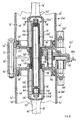
- the brake beam 10 ′ forms part of the brake beam Intermediate housing 66 'furthermore at least part of a drive mechanism 100' of a parking brake added, which is rotatory by a parking brake actuator drivable and with the cylinder piston drives 20a ', 20b' coaxial nut-spindle drive 102 ', wherein the spindle 104' on the pressure side of the piston 74a 'of the one cylinder piston drive 20a 'and the nut 106' on the pressure side of the piston 74b 'of the other cylinder piston drive 20b 'is formed stopable.
- handwheels For applying and releasing the parking brake is, for example, arranged on the side surface of the rail vehicle
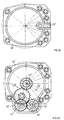
- handwheels have a rotational movement in preferably two parallel to the wheel axles 22 'extending cardan shafts 108', which of the two Sides open into a projecting extension 110 'of the intermediate housing 66' and there are in rotary connection with an input shaft 112 ', 114' of a gear transmission 116 ', which can best be seen in the sectional drawing according to FIG. 12b.
- the two carry Input shafts 112 ', 114' intermeshing spur gears 118 ' are applied a right turn of the handwheels locked and released by turning the left.
- the input shafts 112', 114 ' for example, two gear stages 120'
- the output of the gear transmission 116 'via a central gear 122' which has a coaxial, in the intermediate housing 66 ', cylindrical sleeve 126' preferably supported by roller bearings 124 ' is integrally formed (Fig. 10).
- the central gear 122 'could also be on the Be shrunk sleeve 126 '.
- the ends of the sleeve 126 'and the two bottoms 128' of the Intermediate housing is each interposed a movement seal 130 'around which axially opposite pressure chambers 68 'of the cylinder piston drives 20a', 20b ' to seal the interior of the intermediate housing 66 '.
- the sleeve 126 ' encloses the nut 106' of the nut-spindle drive 102 'and is connected to it in a rotationally fixed manner.
- nut 106 ' is inside the sleeve 126 'axially slidably received. This can be achieved, for example be a coupling between the sleeve 126 'and the nut 106' through a Spline 132 'or a key.
- the entire nut-spindle drive is 102 'relative to the sleeve 126' in the direction of the central axis 62 'of the cylinder piston drives 20a ', 20b' axially displaceable or floating.
- the stop body assigned to the spindle 104 ' 134a ' is non-rotatably connected to it, while that assigned to nut 106' Stop body 134b 'is connected to a stub shaft 140' opposite one with the nut 106 'coupled sleeve-shaped end piece 144', for example by means of a Axial needle bearing 148 'is rotatable.
- the spindle 104 'of the nut spindle drive 102' is inside the nut 106 'can be screwed through a thread 150', so that one over the gear transmission 116 'initiated rotation of the sleeve 126' relative screwing of the spindle 104 ' to the nut 106 ', whereby the nut spindle drive 102' lengthens or shortens.
- these stop bodies 134a, 134b perform a further function as a driver for the pistons 74a, 74b in the event of parking braking.
- stop bodies 134a ', 134b' on the head side complementary to the assigned floors 152 ' the formations 76 'of the pistons 74a', 74b ', for example crowned. Consequently works the described drive mechanism 100 'of the parking brake directly on the pistons 74a', 74b ' the cylinder piston drives 20a ', 20b' which actuate the service brake.
- FIG. 10 shows the release position of the service brake and parking brake, in which the the two pistons 74a ', 74b' in the retracted position the bottoms 128 'of the intermediate housing 66' to contact.
- the stop bodies 134a ', 134b' contact the bottoms 152 'of the pistons 74a ', 74b' in the formations 76 '.
- Fig. 13 shows the situation in which the service brake by pressurizing the Pressure spaces 68 'of the cylinder piston drives 20a', 20b 'are closed, but the parking brake is still resolved. Accordingly, the two pistons move during service braking 74a ', 74b' against the action of the return springs 82 'similar to a boxer arrangement away from each other and actuate via the piston rods 78 'and the angle lever 86 'the push rods 8', whereby the two brake bars 10 ', 12' away from each other and the Brake pads 14 'are pressed against the braking surfaces of the wheels 6'.
- the parking brake is in the application position, because due to a rotational movement introduced into the gear transmission 116 ', the sleeve 126' set in rotation and thereby the in relation to their stop body 134b 'by means of the Axial needle bearing 148 'freely rotatable nut 106' compared to that through its stop body 134a 'screw 104' secured against rotation.
- the situation of 14 can also be caused by first the service brake and then the parking brake is also applied.
- FIGS. 16 and 17 they are opposite the previous example constant and equivalent parts by the marked with the same reference lines. 7 are the perpendicular to the brake beams 10 ', 12' arranged push rods 8 'below a cross member of the bogie.
- the push rods 8 ' are arranged at an angle to one another and diverge preferably starting from the one brake beam 10 ', in which the cylinder-piston drives 20a ', 20b' are included. This allows the push rods 8 'on one central, downwardly drawn section of a cross member 154 'of the bogie 2' on the right and be led past on the left.
- the push rods 8 'could also be used Through openings in the cross member 154 '. In the latter case, it is necessary that for assembly and disassembly of the block brake device 1 ', the push rods 8' of the Brake actuators 20a ', 20b' are easily separable.
- the parking brake device is analogous to that constructed embodiment described above.
Landscapes
- Engineering & Computer Science (AREA)
- Mechanical Engineering (AREA)
- Braking Arrangements (AREA)
- Regulating Braking Force (AREA)
Applications Claiming Priority (2)
| Application Number | Priority Date | Filing Date | Title |
|---|---|---|---|
| DE10304715A DE10304715B4 (de) | 2003-02-06 | 2003-02-06 | Bremsvorrichtung eines Schienenfahrzeugs |
| DE10304715 | 2003-02-06 |
Publications (2)
| Publication Number | Publication Date |
|---|---|
| EP1457401A1 true EP1457401A1 (fr) | 2004-09-15 |
| EP1457401B1 EP1457401B1 (fr) | 2008-04-30 |
Family
ID=32730787
Family Applications (1)
| Application Number | Title | Priority Date | Filing Date |
|---|---|---|---|
| EP04002398A Expired - Lifetime EP1457401B1 (fr) | 2003-02-06 | 2004-02-04 | Système de freinage d'un véhicule ferroviaire |
Country Status (4)
| Country | Link |
|---|---|
| US (1) | US7261189B2 (fr) |
| EP (1) | EP1457401B1 (fr) |
| AT (1) | ATE393724T1 (fr) |
| DE (2) | DE10304715B4 (fr) |
Cited By (4)
| Publication number | Priority date | Publication date | Assignee | Title |
|---|---|---|---|---|
| RU2322367C2 (ru) * | 2006-02-26 | 2008-04-20 | Зао Нпц "Тормоз" | Тормозная система железнодорожного транспортного средства |
| WO2013127769A2 (fr) | 2012-02-29 | 2013-09-06 | Faiveley Transport Nordic Ab | Agencement de frein de stationnement pour un frein de bogie de véhicule ferroviaire |
| CN109094604A (zh) * | 2018-08-14 | 2018-12-28 | 中国铁道科学研究院集团有限公司 | 停放制动装置 |
| JP2020002972A (ja) * | 2018-06-26 | 2020-01-09 | ナブテスコ株式会社 | ブレーキ装置及び鉄道車両 |
Families Citing this family (15)
| Publication number | Priority date | Publication date | Assignee | Title |
|---|---|---|---|---|
| DE102005045879B3 (de) * | 2005-06-23 | 2007-01-04 | Knorr-Bremse Systeme für Schienenfahrzeuge GmbH | Handbremsvorrichtung eines Schienenfahrzeugs mit innerhalb des Handrades angeordnetem Anzeigeelement |
| DE102007063699B4 (de) * | 2007-12-06 | 2011-04-21 | Knorr-Bremse Systeme für Schienenfahrzeuge GmbH | Kombizylinder mit klinkenbetätigter Notlöseeinrichtung für die Feststellbremse |
| DE102008045711A1 (de) * | 2008-09-04 | 2010-03-18 | Knorr-Bremse Systeme für Schienenfahrzeuge GmbH | Pneumatische Bremseinrichtung |
| DE102008051680A1 (de) * | 2008-10-15 | 2010-04-22 | Knorr-Bremse Systeme für Schienenfahrzeuge GmbH | Pneumatischer Bremszylinder |
| DE102008051678A1 (de) | 2008-10-15 | 2010-04-22 | Knorr-Bremse Systeme für Schienenfahrzeuge GmbH | Pneumatischer Bremszylinder |
| DE102008051679B4 (de) * | 2008-10-15 | 2016-07-07 | Knorr-Bremse Systeme für Schienenfahrzeuge GmbH | Pneumatischer Bremszylinder |
| DE102009020548A1 (de) * | 2009-05-08 | 2010-12-16 | Knorr-Bremse Systeme für Schienenfahrzeuge GmbH | Feststellbremseinrichtung eines Schienenfahrzeugs mit hohem Wirkungsgrad |
| RU2483957C1 (ru) * | 2011-09-22 | 2013-06-10 | Федеральное государственное бюджетное образовательное учреждение высшего профессионального образования "Уральский государственный университет путей сообщения" (УрГУПС) | Способ закрепления железнодорожного подвижного состава |
| US9353811B2 (en) * | 2013-11-13 | 2016-05-31 | Akebono Brake Industry Co., Ltd | Electric park brake for a multiple piston caliper |
| US9821822B2 (en) * | 2015-04-06 | 2017-11-21 | New York Air Brake, LLC | Automatic parking brake for truck mounted brake cylinder |
| US9989114B2 (en) * | 2016-06-24 | 2018-06-05 | Akebono Brake Industry Co., Ltd | Power transfer mechanism for a parking brake assembly |
| US11339842B2 (en) | 2019-03-26 | 2022-05-24 | Akebono Brake Industry Co., Ltd. | Brake system with torque distributing assembly |
| EP4400741A1 (fr) | 2020-07-28 | 2024-07-17 | Goodrich Corporation | Elément d'engagement de piston et procédé de fabrication d'un élément d'engagement de piston |
| CN112590849B (zh) * | 2020-12-07 | 2024-06-18 | 中车长江车辆有限公司 | 一种铁路货车转向架制动装置及转向架 |
| CN115571187A (zh) * | 2022-11-03 | 2023-01-06 | 中车山东机车车辆有限公司 | 一种手制动装置 |
Citations (5)
| Publication number | Priority date | Publication date | Assignee | Title |
|---|---|---|---|---|
| GB444996A (en) * | 1934-06-21 | 1936-04-01 | Teves Kg Alfred | Improvements in and relating to vehicle brakes |
| US3101814A (en) * | 1961-12-20 | 1963-08-27 | Westinghouse Air Brake Co | Slack adjusting mechanism for railway car brake apparatus |
| DE4217231A1 (de) * | 1992-05-20 | 1993-11-25 | Deutsche Bahn Ag | Anordnung zur Integration und Entkopplung von Hand- und Druckluftbremse bei räumlich beengten Verhältnissen |
| WO2000002756A1 (fr) | 1998-07-13 | 2000-01-20 | Sab Wabco Ab | Frein de bogie |
| US6186284B1 (en) * | 1998-09-17 | 2001-02-13 | New York Air Brake Corp. | Fluid parking brake for a rail vehicle air brake cylinder |
Family Cites Families (10)
| Publication number | Priority date | Publication date | Assignee | Title |
|---|---|---|---|---|
| US2228818A (en) * | 1938-03-28 | 1941-01-14 | Budd Wheel Co | Brake construction |
| DE951876C (de) * | 1954-11-12 | 1956-11-08 | Wegmann & Co | Handbremsatrieb fuer Schienenfahrzeuge mit Druckluft- oder Vakuumbremse |
| US3759064A (en) * | 1971-09-10 | 1973-09-18 | R Jorn | Composite flexible coupling for interconnecting two shafts |
| DE3021271A1 (de) * | 1979-06-11 | 1981-01-08 | Niesky Waggonbau Veb | Spindelbremse fuer schienenfahrzeuge |
| US4537137A (en) * | 1982-03-01 | 1985-08-27 | White Machinery Corporation | Combination railcar moving vehicle and trailer spotter |
| US4843973A (en) * | 1985-12-19 | 1989-07-04 | Hartelius Marshall V | Railcar moving vehicles |
| CA1325159C (fr) * | 1989-03-17 | 1993-12-14 | Douglas D. Hamilton | Tete d'ebranchage-tronconnage montee sur fleche et support correspondant |
| IT1241010B (it) * | 1990-11-15 | 1993-12-27 | Wabco Westinghouse Compagnia Freni S.P.A. | Attuatore pneumatico doppio con recupero automatico dei giochi per freni di veicoli ferroviari |
| US5303609A (en) * | 1991-06-25 | 1994-04-19 | Kabushiki Kaisha Toyoda Jidoshokki Seisakusho | Toggle type parking brake lever apparatus |
| FR2819469B1 (fr) * | 2001-01-18 | 2003-02-28 | Sagem | Actionneur electromecanique de frein a disques multiples pour moyen de transport, notamment pour avion |
-
2003
- 2003-02-06 DE DE10304715A patent/DE10304715B4/de not_active Expired - Fee Related
-
2004
- 2004-02-04 AT AT04002398T patent/ATE393724T1/de not_active IP Right Cessation
- 2004-02-04 EP EP04002398A patent/EP1457401B1/fr not_active Expired - Lifetime
- 2004-02-04 US US10/770,452 patent/US7261189B2/en not_active Expired - Lifetime
- 2004-02-04 DE DE502004006976T patent/DE502004006976D1/de not_active Expired - Lifetime
Patent Citations (5)
| Publication number | Priority date | Publication date | Assignee | Title |
|---|---|---|---|---|
| GB444996A (en) * | 1934-06-21 | 1936-04-01 | Teves Kg Alfred | Improvements in and relating to vehicle brakes |
| US3101814A (en) * | 1961-12-20 | 1963-08-27 | Westinghouse Air Brake Co | Slack adjusting mechanism for railway car brake apparatus |
| DE4217231A1 (de) * | 1992-05-20 | 1993-11-25 | Deutsche Bahn Ag | Anordnung zur Integration und Entkopplung von Hand- und Druckluftbremse bei räumlich beengten Verhältnissen |
| WO2000002756A1 (fr) | 1998-07-13 | 2000-01-20 | Sab Wabco Ab | Frein de bogie |
| US6186284B1 (en) * | 1998-09-17 | 2001-02-13 | New York Air Brake Corp. | Fluid parking brake for a rail vehicle air brake cylinder |
Cited By (6)
| Publication number | Priority date | Publication date | Assignee | Title |
|---|---|---|---|---|
| RU2322367C2 (ru) * | 2006-02-26 | 2008-04-20 | Зао Нпц "Тормоз" | Тормозная система железнодорожного транспортного средства |
| WO2013127769A2 (fr) | 2012-02-29 | 2013-09-06 | Faiveley Transport Nordic Ab | Agencement de frein de stationnement pour un frein de bogie de véhicule ferroviaire |
| WO2013127769A3 (fr) * | 2012-02-29 | 2014-01-23 | Faiveley Transport Nordic Ab | Agencement de frein de stationnement pour un frein de bogie de véhicule ferroviaire |
| RU2620281C2 (ru) * | 2012-02-29 | 2017-05-24 | Фэйвелей Трэнспорт Нордик Аб | Стояночное тормозное устройство для тормозного механизма тележки рельсового транспортного средства |
| JP2020002972A (ja) * | 2018-06-26 | 2020-01-09 | ナブテスコ株式会社 | ブレーキ装置及び鉄道車両 |
| CN109094604A (zh) * | 2018-08-14 | 2018-12-28 | 中国铁道科学研究院集团有限公司 | 停放制动装置 |
Also Published As
| Publication number | Publication date |
|---|---|
| DE502004006976D1 (de) | 2008-06-12 |
| DE10304715A1 (de) | 2004-08-19 |
| US7261189B2 (en) | 2007-08-28 |
| DE10304715B4 (de) | 2005-04-28 |
| ATE393724T1 (de) | 2008-05-15 |
| US20040168867A1 (en) | 2004-09-02 |
| EP1457401B1 (fr) | 2008-04-30 |
Similar Documents
| Publication | Publication Date | Title |
|---|---|---|
| EP1457401B1 (fr) | Système de freinage d'un véhicule ferroviaire | |
| DE19902556B4 (de) | Lenkgetrieb mit redundantem Antrieb | |
| CH625470A5 (fr) | ||
| DE102011018574A1 (de) | Federungsanordnung für Radaufhängungen von Kraftfahrzeugen | |
| DE202013012672U1 (de) | Scheibenbremse mit einer Synchroneinrichtung | |
| EP0732247B1 (fr) | Frein à disque pour véhicules ferroviaires | |
| EP1457402B1 (fr) | Unité de freinage à sabot pour un bogie d'un véhicule ferroviaire | |
| EP1000829A1 (fr) | Essieu moteur | |
| EP0699846A2 (fr) | Timonerie de frein de véhicules, en particulier pour véhicules de chemin de fer | |
| EP0499971B1 (fr) | Timonerie de frein du type à étrier, notamment pour frein à disque de véhicules ferroviaires | |
| DE1555420A1 (de) | Mehrfachscheibenbremsen fuer radgetriebene Traktoren,insbesondere fuer landwirtschaftliche Zwecke | |
| DE102009042576A1 (de) | Vorrichtung zur aktiven Spureinstellung | |
| DE3202572C2 (fr) | ||
| EP2343229B1 (fr) | Essieu directeur | |
| EP2334524B1 (fr) | Système de freinage pneumatique | |
| DE2237449C2 (de) | Vorrichtung zum Lastausgleich angetriebener Achsen von Drehgestellen bei Schienenfahrzeugen mit Zugelementen | |
| WO1981000835A1 (fr) | Dispositif de freinage pour vehicules sur rails | |
| EP0415009A2 (fr) | Dispositif de freinage, notamment pour véhicules ferroviaires | |
| DE102015220776A1 (de) | Radaufhängung für ein lenkbares Fahrzeugrad eines Kraftfahrzeuges | |
| DE69630592T2 (de) | Kraftübertragungs-Zylinder mit Nachstellfunktion | |
| EP3274243B1 (fr) | Unité d'essieu | |
| DE102024116827B4 (de) | Anordnung einer Schienenfahrzeugbremse und eines Schienenfahrzeugs, insbesondere Güterwagen, mit automatisierter bzw. motorisierter Park- und Feststellbremse und Schienenfahrzeug, insbesondere Güterwagen, mit einer solchen Anordnung | |
| DE2701811C3 (de) | Rollgelenk für ein Geländefahrzeug | |
| EP2078657B1 (fr) | Véhicule sur rails doté d'un dispositif d'absorption de chocs à plusieurs niveaux | |
| DE60105308T2 (de) | Hydropneumatische stellzylinder-einrichtung zum ausrichten in die geradeaus-stellung von lenkenden oder selbst-lenkenden achsen von fahrzeugen |
Legal Events
| Date | Code | Title | Description |
|---|---|---|---|
| PUAI | Public reference made under article 153(3) epc to a published international application that has entered the european phase |
Free format text: ORIGINAL CODE: 0009012 |
|
| AK | Designated contracting states |
Kind code of ref document: A1 Designated state(s): AT BE BG CH CY CZ DE DK EE ES FI FR GB GR HU IE IT LI LU MC NL PT RO SE SI SK TR |
|
| AX | Request for extension of the european patent |
Extension state: AL LT LV MK |
|
| 17P | Request for examination filed |
Effective date: 20050315 |
|
| AKX | Designation fees paid |
Designated state(s): AT BE BG CH CY CZ DE DK EE ES FI FR GB GR HU IE IT LI LU MC NL PT RO SE SI SK TR |
|
| GRAJ | Information related to disapproval of communication of intention to grant by the applicant or resumption of examination proceedings by the epo deleted |
Free format text: ORIGINAL CODE: EPIDOSDIGR1 |
|
| GRAP | Despatch of communication of intention to grant a patent |
Free format text: ORIGINAL CODE: EPIDOSNIGR1 |
|
| GRAP | Despatch of communication of intention to grant a patent |
Free format text: ORIGINAL CODE: EPIDOSNIGR1 |
|
| GRAS | Grant fee paid |
Free format text: ORIGINAL CODE: EPIDOSNIGR3 |
|
| GRAA | (expected) grant |
Free format text: ORIGINAL CODE: 0009210 |
|
| AK | Designated contracting states |
Kind code of ref document: B1 Designated state(s): AT BE BG CH CY CZ DE DK EE ES FI FR GB GR HU IE IT LI LU MC NL PT RO SE SI SK TR |
|
| REG | Reference to a national code |
Ref country code: GB Ref legal event code: FG4D Free format text: NOT ENGLISH |
|
| REG | Reference to a national code |
Ref country code: CH Ref legal event code: EP |
|
| REG | Reference to a national code |
Ref country code: IE Ref legal event code: FG4D Free format text: LANGUAGE OF EP DOCUMENT: GERMAN |
|
| REF | Corresponds to: |
Ref document number: 502004006976 Country of ref document: DE Date of ref document: 20080612 Kind code of ref document: P |
|
| REG | Reference to a national code |
Ref country code: SE Ref legal event code: TRGR |
|
| REG | Reference to a national code |
Ref country code: HU Ref legal event code: AG4A Ref document number: E003302 Country of ref document: HU |
|
| PG25 | Lapsed in a contracting state [announced via postgrant information from national office to epo] |
Ref country code: SI Free format text: LAPSE BECAUSE OF FAILURE TO SUBMIT A TRANSLATION OF THE DESCRIPTION OR TO PAY THE FEE WITHIN THE PRESCRIBED TIME-LIMIT Effective date: 20080430 |
|
| NLV1 | Nl: lapsed or annulled due to failure to fulfill the requirements of art. 29p and 29m of the patents act | ||
| PG25 | Lapsed in a contracting state [announced via postgrant information from national office to epo] |
Ref country code: NL Free format text: LAPSE BECAUSE OF FAILURE TO SUBMIT A TRANSLATION OF THE DESCRIPTION OR TO PAY THE FEE WITHIN THE PRESCRIBED TIME-LIMIT Effective date: 20080430 Ref country code: FI Free format text: LAPSE BECAUSE OF FAILURE TO SUBMIT A TRANSLATION OF THE DESCRIPTION OR TO PAY THE FEE WITHIN THE PRESCRIBED TIME-LIMIT Effective date: 20080430 Ref country code: ES Free format text: LAPSE BECAUSE OF FAILURE TO SUBMIT A TRANSLATION OF THE DESCRIPTION OR TO PAY THE FEE WITHIN THE PRESCRIBED TIME-LIMIT Effective date: 20080810 Ref country code: BG Free format text: LAPSE BECAUSE OF FAILURE TO SUBMIT A TRANSLATION OF THE DESCRIPTION OR TO PAY THE FEE WITHIN THE PRESCRIBED TIME-LIMIT Effective date: 20080730 Ref country code: PT Free format text: LAPSE BECAUSE OF FAILURE TO SUBMIT A TRANSLATION OF THE DESCRIPTION OR TO PAY THE FEE WITHIN THE PRESCRIBED TIME-LIMIT Effective date: 20080930 |
|
| REG | Reference to a national code |
Ref country code: IE Ref legal event code: FD4D |
|
| ET | Fr: translation filed | ||
| PG25 | Lapsed in a contracting state [announced via postgrant information from national office to epo] |
Ref country code: IE Free format text: LAPSE BECAUSE OF FAILURE TO SUBMIT A TRANSLATION OF THE DESCRIPTION OR TO PAY THE FEE WITHIN THE PRESCRIBED TIME-LIMIT Effective date: 20080430 Ref country code: DK Free format text: LAPSE BECAUSE OF FAILURE TO SUBMIT A TRANSLATION OF THE DESCRIPTION OR TO PAY THE FEE WITHIN THE PRESCRIBED TIME-LIMIT Effective date: 20080430 Ref country code: CZ Free format text: LAPSE BECAUSE OF FAILURE TO SUBMIT A TRANSLATION OF THE DESCRIPTION OR TO PAY THE FEE WITHIN THE PRESCRIBED TIME-LIMIT Effective date: 20080430 |
|
| PG25 | Lapsed in a contracting state [announced via postgrant information from national office to epo] |
Ref country code: SK Free format text: LAPSE BECAUSE OF FAILURE TO SUBMIT A TRANSLATION OF THE DESCRIPTION OR TO PAY THE FEE WITHIN THE PRESCRIBED TIME-LIMIT Effective date: 20080430 Ref country code: RO Free format text: LAPSE BECAUSE OF FAILURE TO SUBMIT A TRANSLATION OF THE DESCRIPTION OR TO PAY THE FEE WITHIN THE PRESCRIBED TIME-LIMIT Effective date: 20080430 |
|
| PLBE | No opposition filed within time limit |
Free format text: ORIGINAL CODE: 0009261 |
|
| STAA | Information on the status of an ep patent application or granted ep patent |
Free format text: STATUS: NO OPPOSITION FILED WITHIN TIME LIMIT |
|
| 26N | No opposition filed |
Effective date: 20090202 |
|
| PG25 | Lapsed in a contracting state [announced via postgrant information from national office to epo] |
Ref country code: EE Free format text: LAPSE BECAUSE OF FAILURE TO SUBMIT A TRANSLATION OF THE DESCRIPTION OR TO PAY THE FEE WITHIN THE PRESCRIBED TIME-LIMIT Effective date: 20080430 |
|
| BERE | Be: lapsed |
Owner name: KNORR-BREMSE SYSTEME FUR SCHIENENFAHRZEUGE G.M.B. Effective date: 20090228 |
|
| PG25 | Lapsed in a contracting state [announced via postgrant information from national office to epo] |
Ref country code: MC Free format text: LAPSE BECAUSE OF NON-PAYMENT OF DUE FEES Effective date: 20090228 |
|
| REG | Reference to a national code |
Ref country code: CH Ref legal event code: PL |
|
| GBPC | Gb: european patent ceased through non-payment of renewal fee |
Effective date: 20090204 |
|
| PG25 | Lapsed in a contracting state [announced via postgrant information from national office to epo] |
Ref country code: LI Free format text: LAPSE BECAUSE OF NON-PAYMENT OF DUE FEES Effective date: 20090228 Ref country code: CH Free format text: LAPSE BECAUSE OF NON-PAYMENT OF DUE FEES Effective date: 20090228 |
|
| PG25 | Lapsed in a contracting state [announced via postgrant information from national office to epo] |
Ref country code: BE Free format text: LAPSE BECAUSE OF NON-PAYMENT OF DUE FEES Effective date: 20090228 |
|
| PG25 | Lapsed in a contracting state [announced via postgrant information from national office to epo] |
Ref country code: GB Free format text: LAPSE BECAUSE OF NON-PAYMENT OF DUE FEES Effective date: 20090204 |
|
| PG25 | Lapsed in a contracting state [announced via postgrant information from national office to epo] |
Ref country code: AT Free format text: LAPSE BECAUSE OF NON-PAYMENT OF DUE FEES Effective date: 20090204 |
|
| PG25 | Lapsed in a contracting state [announced via postgrant information from national office to epo] |
Ref country code: GR Free format text: LAPSE BECAUSE OF FAILURE TO SUBMIT A TRANSLATION OF THE DESCRIPTION OR TO PAY THE FEE WITHIN THE PRESCRIBED TIME-LIMIT Effective date: 20080731 |
|
| PG25 | Lapsed in a contracting state [announced via postgrant information from national office to epo] |
Ref country code: LU Free format text: LAPSE BECAUSE OF NON-PAYMENT OF DUE FEES Effective date: 20090204 |
|
| PG25 | Lapsed in a contracting state [announced via postgrant information from national office to epo] |
Ref country code: TR Free format text: LAPSE BECAUSE OF FAILURE TO SUBMIT A TRANSLATION OF THE DESCRIPTION OR TO PAY THE FEE WITHIN THE PRESCRIBED TIME-LIMIT Effective date: 20080430 |
|
| PG25 | Lapsed in a contracting state [announced via postgrant information from national office to epo] |
Ref country code: CY Free format text: LAPSE BECAUSE OF FAILURE TO SUBMIT A TRANSLATION OF THE DESCRIPTION OR TO PAY THE FEE WITHIN THE PRESCRIBED TIME-LIMIT Effective date: 20080430 |
|
| REG | Reference to a national code |
Ref country code: FR Ref legal event code: PLFP Year of fee payment: 13 |
|
| REG | Reference to a national code |
Ref country code: FR Ref legal event code: PLFP Year of fee payment: 14 |
|
| REG | Reference to a national code |
Ref country code: FR Ref legal event code: PLFP Year of fee payment: 15 |
|
| PGFP | Annual fee paid to national office [announced via postgrant information from national office to epo] |
Ref country code: FR Payment date: 20210218 Year of fee payment: 18 Ref country code: IT Payment date: 20210226 Year of fee payment: 18 |
|
| PGFP | Annual fee paid to national office [announced via postgrant information from national office to epo] |
Ref country code: DE Payment date: 20210223 Year of fee payment: 18 Ref country code: SE Payment date: 20210222 Year of fee payment: 18 Ref country code: HU Payment date: 20210123 Year of fee payment: 18 |
|
| REG | Reference to a national code |
Ref country code: DE Ref legal event code: R119 Ref document number: 502004006976 Country of ref document: DE |
|
| REG | Reference to a national code |
Ref country code: SE Ref legal event code: EUG |
|
| PG25 | Lapsed in a contracting state [announced via postgrant information from national office to epo] |
Ref country code: SE Free format text: LAPSE BECAUSE OF NON-PAYMENT OF DUE FEES Effective date: 20220205 |
|
| PG25 | Lapsed in a contracting state [announced via postgrant information from national office to epo] |
Ref country code: HU Free format text: LAPSE BECAUSE OF NON-PAYMENT OF DUE FEES Effective date: 20220205 |
|
| PG25 | Lapsed in a contracting state [announced via postgrant information from national office to epo] |
Ref country code: FR Free format text: LAPSE BECAUSE OF NON-PAYMENT OF DUE FEES Effective date: 20220228 |
|
| PG25 | Lapsed in a contracting state [announced via postgrant information from national office to epo] |
Ref country code: DE Free format text: LAPSE BECAUSE OF NON-PAYMENT OF DUE FEES Effective date: 20220901 |
|
| PG25 | Lapsed in a contracting state [announced via postgrant information from national office to epo] |
Ref country code: IT Free format text: LAPSE BECAUSE OF NON-PAYMENT OF DUE FEES Effective date: 20220204 |