EP1458075B1 - Integrierte Stroverteilung und Gateway für einen Fahrzeug - Google Patents
Integrierte Stroverteilung und Gateway für einen Fahrzeug Download PDFInfo
- Publication number
- EP1458075B1 EP1458075B1 EP04005559A EP04005559A EP1458075B1 EP 1458075 B1 EP1458075 B1 EP 1458075B1 EP 04005559 A EP04005559 A EP 04005559A EP 04005559 A EP04005559 A EP 04005559A EP 1458075 B1 EP1458075 B1 EP 1458075B1
- Authority
- EP
- European Patent Office
- Prior art keywords
- module
- power
- power distribution
- distribution module
- outputs
- Prior art date
- Legal status (The legal status is an assumption and is not a legal conclusion. Google has not performed a legal analysis and makes no representation as to the accuracy of the status listed.)
- Expired - Lifetime
Links
Images

Classifications
-
- B—PERFORMING OPERATIONS; TRANSPORTING
- B60—VEHICLES IN GENERAL
- B60R—VEHICLES, VEHICLE FITTINGS, OR VEHICLE PARTS, NOT OTHERWISE PROVIDED FOR
- B60R16/00—Electric or fluid circuits specially adapted for vehicles and not otherwise provided for; Arrangement of elements of electric or fluid circuits specially adapted for vehicles and not otherwise provided for
- B60R16/02—Electric or fluid circuits specially adapted for vehicles and not otherwise provided for; Arrangement of elements of electric or fluid circuits specially adapted for vehicles and not otherwise provided for electric constitutive elements
- B60R16/023—Electric or fluid circuits specially adapted for vehicles and not otherwise provided for; Arrangement of elements of electric or fluid circuits specially adapted for vehicles and not otherwise provided for electric constitutive elements for transmission of signals between vehicle parts or subsystems
-
- H—ELECTRICITY
- H02—GENERATION; CONVERSION OR DISTRIBUTION OF ELECTRIC POWER
- H02J—ELECTRIC POWER NETWORKS; CIRCUIT ARRANGEMENTS OR SYSTEMS FOR SUPPLYING OR DISTRIBUTING ELECTRIC POWER; SYSTEMS FOR STORING ELECTRIC ENERGY
- H02J1/00—Circuit arrangements for DC mains or DC distribution networks
- H02J1/14—Balancing load and power generation in DC networks
-
- B—PERFORMING OPERATIONS; TRANSPORTING
- B60—VEHICLES IN GENERAL
- B60R—VEHICLES, VEHICLE FITTINGS, OR VEHICLE PARTS, NOT OTHERWISE PROVIDED FOR
- B60R16/00—Electric or fluid circuits specially adapted for vehicles and not otherwise provided for; Arrangement of elements of electric or fluid circuits specially adapted for vehicles and not otherwise provided for
- B60R16/02—Electric or fluid circuits specially adapted for vehicles and not otherwise provided for; Arrangement of elements of electric or fluid circuits specially adapted for vehicles and not otherwise provided for electric constitutive elements
- B60R16/03—Electric or fluid circuits specially adapted for vehicles and not otherwise provided for; Arrangement of elements of electric or fluid circuits specially adapted for vehicles and not otherwise provided for electric constitutive elements for supply of electrical power to vehicle subsystems or for
-
- H—ELECTRICITY
- H02—GENERATION; CONVERSION OR DISTRIBUTION OF ELECTRIC POWER
- H02J—ELECTRIC POWER NETWORKS; CIRCUIT ARRANGEMENTS OR SYSTEMS FOR SUPPLYING OR DISTRIBUTING ELECTRIC POWER; SYSTEMS FOR STORING ELECTRIC ENERGY
- H02J2105/00—Networks for supplying or distributing electric power characterised by their spatial reach or by the load
- H02J2105/30—Networks for supplying or distributing electric power characterised by their spatial reach or by the load the load networks being external to vehicles, i.e. exchanging power with vehicles
- H02J2105/33—Networks for supplying or distributing electric power characterised by their spatial reach or by the load the load networks being external to vehicles, i.e. exchanging power with vehicles exchanging power with road vehicles
Definitions
- the present invention relates generally to both vehicle electrical power management and vehicle communication controls,
- motor vehicles typically include one or more systems arranged to control operation of various vehicle electrical loads as needed or demanded during operation of the vehicle.
- Such systems are typically arranged as power modules, one or more of which are located in various areas in the vehicle.
- These modules are generally connected to the vehicle's electrical power supply, and include control circuitry responsive to inputs from various control switches and/or control devices to selectively connect various output loads to the vehicle's power system as needed/desired.
- operation of a turn signal indicator lever inside the vehicle creates an input signal received at a power module, which in turn through a set of electro-mechanical relays and/or other electrical switching elements, sends electrical power to the appropriate turn signal indicator lamp.
- the power module acts as a centralized electrical power switching device to facilitate management and control of various electrical components/loads on the vehicle.
- electrical components and controllers located in vehicles are generally connected to at least one communication bus to facilitate exchange and communication of data throughout the vehicle.
- two such available communication bus arrangements are the J1850 communication bus and the CAN communication bus arrangement.
- each bus can operate at different multiplex speeds.
- Known arrangements include the CAN A, CAN B, and CAN C buses.
- the gateway operates as: (1) a portal to facilitate data transfer between devices that communicate on one or more of the buses, e.g., at different bus speeds, and (2) a portal for connection to external diagnostic equipment.
- EP-A- 0 754 599 discloses a vehicle electric power distribution module as recited in the pre-characterization section of claim 1 herein.
- the subject invention is directed to a universal vehicle electric power distribution module as recited in claim 1 herein.
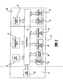
- module 10 includes a base or common architecture In which a set of predetermined electrical loads (one or more electrical loads/vehicle content common to multiple vehicle models) are configured for control as a base configuration controller board 12.
- the base module includes a microcontroller based controller 14 arranged to receive input signals from at least one reconfigurable input connection 16, as well as one or more fixed input connections 18 (optional/as desired).
- Two types of outputs are provided from the controller 14, relay-type output connections, and pulse width modulated (PWM) type outputs.
- the relay outputs are reconfigurable (20) and/or fixed (22).
- the PWM outputs are also reconfigurable (24) and/or fixed (26). While not to be construed as limiting, fixed inputs/outputs preferably include nonserviceable-type control elements.
- a suitable communication gateway device such as a CAN gateway 28, is also connected to controller 14. Controller 14 is arranged to selectively couple vehicle power to provide operational control of the coupled vehicle components/eletrical loads.
- loads controllable by an integrated module of the present invention include one or more of the following: auto shutdown switching, fuel pump switching, starter motor switching, distributed ignition control, head lamp control, turn signal control, reverse lamp control, stop lamp control, front wiper control, horn control, front HVAC blower, cooling fan control, AC condenser fan control, secondary flow valve switching electric backlight control, diesel cabin heater control, rear fog lamp control, electronic stability brake lamp inhibit, transfer case control, underhood lamp, headlamp leveling, trailer tow lighting control, rear wiper and washer control, and rear HVAC blower control.
- the controller is able to assign a function of a particular connector via programming and an internal look-up table.
- a common wiring connector/harness can be used with the module even through a particular connector pin is configured to be connected to different components on different vehicle models.
- a module 10 can be easily sealed to provide control of optional (and/or higher level content) vehicle electrical loads/components. Such additional loads/components would be controlled by appropriate inputs, outputs, and PWM outputs (denoted as scalable inputs 30, scalable relay outputs 32, and scalable PWM outputs 34 In Figure 1 ) added by way of an enlarged controller board 12a and/or connected sub-board.
- PWM outputs denoted as scalable inputs 30, scalable relay outputs 32, and scalable PWM outputs 34 In Figure 1
- module 10 is readily packaged to allow easy expansion as needed for use with different vehicle types and models.
- the outputs can be selectively controlled by operation of one or more programmable power management switches.
- programmable power management switches in lieu of electromechanical relays or conventional silicon-type switches allows a module 10
- high current type loads e.g., the aforementioned front wiper, cooling fan, and/or front HVAC blower, and mid/low current loads with the same module.
- high current loads have not heretofore been controlled together with lower current loads in known power modules because of size and heat issues associated with conventional high current control devices.
- FIG. 2 a cross-sectional block diagram of a module layout 100 illustrates - the present invention. More specifically, a compact design and significant cost savings are realized by locating all high current control devices on both sides of a single base module board 102 formed from a double-sided, high current rated (e.g., a "10 ounce copper") circuit board. Scalability is provided (i.e., optional expansion) such as by using a larger board 102a. Mid and low current devices can be packaged on a lower current rated circuit board 104. Boards 102 and 104 can be positioned within a module housing 106 at right angles relative to each other as depicted in Figure 2 , The respective circuit boards are coupled together via connection 108.
- a double-sided, high current rated e.g., a "10 ounce copper”
Landscapes
- Engineering & Computer Science (AREA)
- Power Engineering (AREA)
- Mechanical Engineering (AREA)
- Remote Monitoring And Control Of Power-Distribution Networks (AREA)
- Direct Current Feeding And Distribution (AREA)
Claims (14)
- Universelles Stromverteilungsmodul (10) für ein Fahrzeug, wobei das Modul folgendes umfasst:eine Mehrzahl von rekonfigurierbaren Moduleingängen (16);eine Mikrocontroller (14), der für einen Empfang von Signalen gekoppelt ist, die an den rekonfigurierbaren Moduleingängen erscheinen; undeine Mehrzahl von rekonfigurierbaren Modulausgängen (20, 24), die gesteuert durch den Mikrocontroller (14) so funktionsfähig sind, dass sie elektrischen Strom selektiv mit einer entsprechenden Mehrzahl von elektrischen Verbrauchern in dem Fahrzeug koppeln; dadurch gekennzeichnet, dass ein erster Abschnitt der Modulausgänge Strom innerhalb eines ersten Bereichs von Stromwerten bereitstellt, und wobei ein zweiter Abschnitt der Modulausgänge Strom innerhalb eines zweiten Bereichs von Stromwerten bereitstellt, und wobei der erste Abschnitt der Modulausgänge auf einer ersten Leiterplatte (102) platziert ist, die für den ersten Bereich ausgelegt ist, und wobei der zweite Abschnitt von Modulausgängen auf einer zweiten Leiterplatte (104) platziert ist, die für den zweiten Bereich ausgelegt ist.
- Stromverteilungsmodul (10) nach Anspruch 1, wobei die Moduleingänge und die Modulausgänge gemäß dem Inhalt einer Verweistabelle, die in dem Mikrocontroller gespeichert ist, rekonfigurierbar sind.
- Stromverteilungsmodul (10) nach Anspruch 1, wobei dieses ferner mindestens einen nicht-rekonfigurierbaren Eingang (18) umfasst.
- Stromverteilungsmodul (10) nach Anspruch 1, wobei dieses ferner mindestens einen nicht-rekonfigurierbaren Ausgang umfasst.
- Stromverteilungsmodul (10) nach Anspruch 1, wobei das Modul skalierbar ist, so dass es eine Steuerung zusätzlicher elektrischer Verbraucher des Fahrzeugs bereitstellt.
- Stromverteilungsmodul (10) nach Anspruch 1, wobei die Mehrzahl von Modulausgängen mindestens einen Ausgang (34) aufweist, der die Bereitstellung von elektrischem Strom über Pulsbreitenmodulation steuert.
- Stromverteilungsmodul (10) nach Anspruch 1, wobei die Mehrzahl von Modulausgängen mindestens einen Ausgang aufweist, der die Bereitstellung von elektrischem Strom über einen Leistungsschalter steuert.
- Stromverteilungsmodul (10) nach Anspruch 7, wobei der Leistungsschalter ein Relais umfasst.
- Stromverteilungsmodul (10) nach Anspruch 7, wobei der Leistungsschalter einen Halbleiterschalter umfasst.
- Stromverteilungsmodul (10) nach Anspruch 7, wobei der Leistungsschalter einen programmierbaren Energieverwaltungsschalter umfasst.
- Stromverteilungsmodul (10) nach Anspruch 1, wobei dieses ferner eine Kommunikationsbus-Gateway-Anordnung umfasst.
- Stromverteilungsmodul (10) nach Anspruch 1, wobei die Mehrzahl von Modulausgängen erste und zweite Ausgänge aufweist, welche jeweils die Bereitstellung von elektrischem Strom an deren entsprechenden Verbraucher über entsprechende erste und zweite programmierbare Energieverwaltungsschalter steuern, wobei der erste Energieverwaltungsschalter für die Umschaltung des elektrischen Stroms auf einem ersten Wert programmiert ist, und wobei der zweite Energieverwaltungsschalter für die Umschaltung des elektrischen Stroms auf einem zweiten Wert programmiert ist.
- Stromverteilungsmodul (10) nach Anspruch 1, wobei dieses ferner ein Modulgehäuse umfasst, wobei sich die erste Leiterplatte längs transversal zu einer Längsausdehnung der zweiten Leiterplatte erstreckt.
- Stromverteilungsmodul (10) nach Anspruch 13, wobei sich die ersten und zweiten Leiterplatten (102, 104) im Wesentlichen in rechten Winkeln zueinander erstrecken.
Applications Claiming Priority (2)
| Application Number | Priority Date | Filing Date | Title |
|---|---|---|---|
| US45330003P | 2003-03-10 | 2003-03-10 | |
| US453300P | 2003-03-10 |
Publications (3)
| Publication Number | Publication Date |
|---|---|
| EP1458075A2 EP1458075A2 (de) | 2004-09-15 |
| EP1458075A3 EP1458075A3 (de) | 2006-08-09 |
| EP1458075B1 true EP1458075B1 (de) | 2012-10-10 |
Family
ID=32772094
Family Applications (1)
| Application Number | Title | Priority Date | Filing Date |
|---|---|---|---|
| EP04005559A Expired - Lifetime EP1458075B1 (de) | 2003-03-10 | 2004-03-09 | Integrierte Stroverteilung und Gateway für einen Fahrzeug |
Country Status (3)
| Country | Link |
|---|---|
| US (1) | US7064658B2 (de) |
| EP (1) | EP1458075B1 (de) |
| CA (1) | CA2460457C (de) |
Families Citing this family (22)
| Publication number | Priority date | Publication date | Assignee | Title |
|---|---|---|---|---|
| US7463139B2 (en) * | 2004-10-18 | 2008-12-09 | Stmicroelectronics, Inc. | Method and system for driving a vehicle trailer tow connector |
| US20070228826A1 (en) * | 2006-03-31 | 2007-10-04 | Jordan Patrick D | Modular, extensible electrical and communication systems, methods, and devices |
| JP5426102B2 (ja) | 2007-02-28 | 2014-02-26 | エスティーマイクロエレクトロニクス,インコーポレイテッド | 車両のバッテリチャージを保存し且つトレーラー負荷を保護する集積回路及び方法 |
| WO2008116224A1 (en) * | 2007-03-22 | 2008-09-25 | Stoneridge Control Devices, Inc. | Trailer tow connector assembly |
| US7642670B2 (en) * | 2007-08-13 | 2010-01-05 | Glenn Rosendahl | Controlling power supply to vehicles through a series of electrical outlets |
| US7679493B1 (en) | 2008-01-21 | 2010-03-16 | Yazaki North America, Inc. | Boat trailer submersion |
| US8179142B2 (en) * | 2008-03-11 | 2012-05-15 | Cequent Electric Products | Trailer signal converter |
| US9102267B2 (en) | 2008-03-11 | 2015-08-11 | Cequent Performance Products, Inc. | Trailer signal converter |
| US7746219B1 (en) | 2008-04-08 | 2010-06-29 | Yazaki North America | Method and apparatus for adjusting trailer electrical load limits |
| KR101293957B1 (ko) * | 2011-06-13 | 2013-08-07 | 기아자동차주식회사 | 스톱램프 구동장치 |
| US9785156B2 (en) * | 2012-06-12 | 2017-10-10 | Panasonic Intellectual Property Management Co., Ltd. | Motor control system, method, and device for changing control software for a vehicle cooling blower |
| FR3039108A1 (fr) * | 2015-07-20 | 2017-01-27 | Peugeot Citroen Automobiles Sa | Dispositif de controle du fonctionnement d’une source de retroeclairage d’organe(s) de commande de vitre(s) electrique(s) de vehicule |
| US10093232B2 (en) | 2015-09-16 | 2018-10-09 | Truck-Lite Co., Llc | Telematics road ready system |
| US10388161B2 (en) | 2015-09-16 | 2019-08-20 | Truck-Lite Co., Llc | Telematics road ready system with user interface |
| US10040412B2 (en) * | 2016-05-10 | 2018-08-07 | Deere & Company | Utility vehicle power distribution module |
| US10909785B2 (en) | 2017-03-06 | 2021-02-02 | Trimark Corporation | Base control module for vehicles |
| US20190268675A1 (en) | 2017-03-15 | 2019-08-29 | Scott Troutman | Telematics Road Ready System including a Bridge Integrator Unit |
| CN108382324A (zh) * | 2018-01-18 | 2018-08-10 | 沈阳中科唯电子技术有限公司 | 一种集成网关功能的低功耗整车控制器 |
| CN108638957B (zh) * | 2018-05-11 | 2021-10-26 | 长安大学 | 一种夜间低能见度下自动开启车辆雾灯的装置及方法 |
| CN113382891B (zh) | 2018-11-29 | 2025-02-25 | 格罗特工业有限公司 | 用于选择卡车拖车上的灯功能的适配器 |
| JP7334614B2 (ja) * | 2019-12-24 | 2023-08-29 | 株式会社オートネットワーク技術研究所 | 車載中継装置 |
| WO2024020090A1 (en) * | 2022-07-20 | 2024-01-25 | Allison Transmission, Inc. | High voltage distribution module for electric vehicle |
Family Cites Families (6)
| Publication number | Priority date | Publication date | Assignee | Title |
|---|---|---|---|---|
| US4354241A (en) * | 1979-12-27 | 1982-10-12 | Butler Manufacturing Company | Programmable electronic real-time load controller providing for adaptation of load control in response to varying environmental conditions |
| EP0754599B1 (de) * | 1995-07-19 | 2001-10-10 | Yazaki Corporation | Kraftfahrzeugverbraucher-Steuerungssystem |
| DE19703236A1 (de) * | 1997-01-29 | 1998-07-30 | Siemens Ag | Schalteranordnung für elektrische Steuergeräte |
| US6263269B1 (en) * | 1998-12-23 | 2001-07-17 | International Truck And Engine Corporation | Configuration programming of input/output connections for network modules in a multiplexed vehicle communication system |
| US7020790B2 (en) * | 2001-02-08 | 2006-03-28 | Honeywell International Inc. | Electric load management center including gateway module and multiple load management modules for distributing power to multiple loads |
| US6985343B2 (en) | 2002-04-19 | 2006-01-10 | Daimlerchrysler Corporation | Programmable power management switch |
-
2004
- 2004-03-05 US US10/794,990 patent/US7064658B2/en not_active Expired - Lifetime
- 2004-03-09 EP EP04005559A patent/EP1458075B1/de not_active Expired - Lifetime
- 2004-03-10 CA CA2460457A patent/CA2460457C/en not_active Expired - Fee Related
Also Published As
| Publication number | Publication date |
|---|---|
| US7064658B2 (en) | 2006-06-20 |
| EP1458075A3 (de) | 2006-08-09 |
| US20040189092A1 (en) | 2004-09-30 |
| CA2460457C (en) | 2012-05-29 |
| EP1458075A2 (de) | 2004-09-15 |
| CA2460457A1 (en) | 2004-09-10 |
Similar Documents
| Publication | Publication Date | Title |
|---|---|---|
| CA2460457C (en) | Integrated vehicle power distribution and gateway system | |
| JP6374897B2 (ja) | 車両用ワイヤハーネス構造 | |
| JP4139261B2 (ja) | フロント電装システム、フロント電装システム用電子制御ユニット及び電装コネクタ | |
| US6982648B2 (en) | Lighting or indicating light unit for a vehicle and lighting or indicating system equipped with at least one such light unit | |
| US5793615A (en) | Multiplex control of components and subsystems in motor vehicles | |
| US20190173240A1 (en) | In-vehicle control system and wire harness | |
| JP2000504509A (ja) | 自動車に設けられた機能モジュール用の回路装置 | |
| EP1210241A1 (de) | Umrüstbare modulare instrumentenkonsole | |
| US5801925A (en) | Electronic integration in service boxes | |
| KR100348839B1 (ko) | 차량용전원공급장치 | |
| US7983050B2 (en) | Pluggable system for reading inputs, controlling outputs and communicating with another module for power distribution unit | |
| US10562473B2 (en) | Electric current distribution system for a vehicle | |
| CN209757019U (zh) | 一种车载电器系统线束架构及汽车 | |
| KR101143873B1 (ko) | 차량의 전원 제어장치용 플러그-인 타입 전원 제어 아이피에스 모듈 | |
| JP2006062594A (ja) | 車室内ランプ制御システム | |
| US20130179033A1 (en) | Vehicle control circuit | |
| US6909952B2 (en) | Device for controlling/regulating the operational sequences in a motor vehicle | |
| JP6535200B2 (ja) | 車室環境用機能部品接続システム | |
| JP6630333B2 (ja) | 車載制御装置 | |
| US20050219827A1 (en) | Electrical circuit device | |
| JP3257685B2 (ja) | 電源分配システム | |
| GB2346352A (en) | Electrical wiring in the dashboard of a vehicle | |
| KR20100058366A (ko) | 통신형 정션 박스 | |
| JPH05146080A (ja) | 車載用電源分配システム | |
| JPH11301375A (ja) | 電源分配装置 |
Legal Events
| Date | Code | Title | Description |
|---|---|---|---|
| PUAI | Public reference made under article 153(3) epc to a published international application that has entered the european phase |
Free format text: ORIGINAL CODE: 0009012 |
|
| AK | Designated contracting states |
Kind code of ref document: A2 Designated state(s): AT BE BG CH CY CZ DE DK EE ES FI FR GB GR HU IE IT LI LU MC NL PL PT RO SE SI SK TR |
|
| AX | Request for extension of the european patent |
Extension state: AL LT LV MK |
|
| RIN1 | Information on inventor provided before grant (corrected) |
Inventor name: NARBUS, PETER J. Inventor name: GAYNIER, JOHN M. Inventor name: CHUPP, BRADLEY S. Inventor name: BURLAK, GARY Inventor name: FRASER, ROD S. Inventor name: LONG, MICHAEL C. Inventor name: MORENILLA, LUIS J. Inventor name: TROVATO, FRANK Inventor name: COX, MICHAEL A. Inventor name: MIROWSKI, MARIAN |
|
| PUAL | Search report despatched |
Free format text: ORIGINAL CODE: 0009013 |
|
| AK | Designated contracting states |
Kind code of ref document: A3 Designated state(s): AT BE BG CH CY CZ DE DK EE ES FI FR GB GR HU IE IT LI LU MC NL PL PT RO SE SI SK TR |
|
| AX | Request for extension of the european patent |
Extension state: AL LT LV MK |
|
| 17P | Request for examination filed |
Effective date: 20061124 |
|
| AKX | Designation fees paid |
Designated state(s): DE FR GB |
|
| RAP1 | Party data changed (applicant data changed or rights of an application transferred) |
Owner name: CHRYSLER LLC |
|
| 17Q | First examination report despatched |
Effective date: 20091123 |
|
| RAP1 | Party data changed (applicant data changed or rights of an application transferred) |
Owner name: CHRYSLER GROUP LLC |
|
| GRAP | Despatch of communication of intention to grant a patent |
Free format text: ORIGINAL CODE: EPIDOSNIGR1 |
|
| GRAS | Grant fee paid |
Free format text: ORIGINAL CODE: EPIDOSNIGR3 |
|
| GRAA | (expected) grant |
Free format text: ORIGINAL CODE: 0009210 |
|
| AK | Designated contracting states |
Kind code of ref document: B1 Designated state(s): DE FR GB |
|
| REG | Reference to a national code |
Ref country code: GB Ref legal event code: FG4D |
|
| REG | Reference to a national code |
Ref country code: DE Ref legal event code: R096 Ref document number: 602004039595 Country of ref document: DE Effective date: 20121206 |
|
| PLBE | No opposition filed within time limit |
Free format text: ORIGINAL CODE: 0009261 |
|
| STAA | Information on the status of an ep patent application or granted ep patent |
Free format text: STATUS: NO OPPOSITION FILED WITHIN TIME LIMIT |
|
| 26N | No opposition filed |
Effective date: 20130711 |
|
| REG | Reference to a national code |
Ref country code: DE Ref legal event code: R097 Ref document number: 602004039595 Country of ref document: DE Effective date: 20130711 |
|
| REG | Reference to a national code |
Ref country code: FR Ref legal event code: PLFP Year of fee payment: 13 |
|
| REG | Reference to a national code |
Ref country code: FR Ref legal event code: PLFP Year of fee payment: 14 |
|
| REG | Reference to a national code |
Ref country code: FR Ref legal event code: PLFP Year of fee payment: 15 |
|
| PGFP | Annual fee paid to national office [announced via postgrant information from national office to epo] |
Ref country code: FR Payment date: 20210325 Year of fee payment: 18 |
|
| PGFP | Annual fee paid to national office [announced via postgrant information from national office to epo] |
Ref country code: GB Payment date: 20210329 Year of fee payment: 18 Ref country code: DE Payment date: 20210329 Year of fee payment: 18 |
|
| REG | Reference to a national code |
Ref country code: DE Ref legal event code: R119 Ref document number: 602004039595 Country of ref document: DE |
|
| GBPC | Gb: european patent ceased through non-payment of renewal fee |
Effective date: 20220309 |
|
| PG25 | Lapsed in a contracting state [announced via postgrant information from national office to epo] |
Ref country code: GB Free format text: LAPSE BECAUSE OF NON-PAYMENT OF DUE FEES Effective date: 20220309 Ref country code: FR Free format text: LAPSE BECAUSE OF NON-PAYMENT OF DUE FEES Effective date: 20220331 Ref country code: DE Free format text: LAPSE BECAUSE OF NON-PAYMENT OF DUE FEES Effective date: 20221001 |