EP1458268B1 - Dampfdruck-kochgerät mit temperatursensor - Google Patents
Dampfdruck-kochgerät mit temperatursensor Download PDFInfo
- Publication number
- EP1458268B1 EP1458268B1 EP02799113A EP02799113A EP1458268B1 EP 1458268 B1 EP1458268 B1 EP 1458268B1 EP 02799113 A EP02799113 A EP 02799113A EP 02799113 A EP02799113 A EP 02799113A EP 1458268 B1 EP1458268 B1 EP 1458268B1
- Authority
- EP
- European Patent Office
- Prior art keywords
- timer
- pressure
- appliance
- cooking
- temperature sensor
- Prior art date
- Legal status (The legal status is an assumption and is not a legal conclusion. Google has not performed a legal analysis and makes no representation as to the accuracy of the status listed.)
- Expired - Lifetime
Links
- 238000010411 cooking Methods 0.000 title claims abstract description 79
- 235000013305 food Nutrition 0.000 title claims description 12
- 238000004891 communication Methods 0.000 claims abstract description 10
- 238000000034 method Methods 0.000 claims description 12
- 230000001960 triggered effect Effects 0.000 claims description 4
- 230000005236 sound signal Effects 0.000 claims description 2
- 238000012544 monitoring process Methods 0.000 claims 1
- 230000001105 regulatory effect Effects 0.000 abstract description 5
- 230000001276 controlling effect Effects 0.000 description 5
- 238000001514 detection method Methods 0.000 description 3
- 230000003416 augmentation Effects 0.000 description 2
- 238000010586 diagram Methods 0.000 description 2
- 210000000056 organ Anatomy 0.000 description 2
- 230000000007 visual effect Effects 0.000 description 2
- 230000002618 waking effect Effects 0.000 description 2
- 101100536354 Drosophila melanogaster tant gene Proteins 0.000 description 1
- 230000005355 Hall effect Effects 0.000 description 1
- 230000004397 blinking Effects 0.000 description 1
- 230000006835 compression Effects 0.000 description 1
- 238000007906 compression Methods 0.000 description 1
- 238000006073 displacement reaction Methods 0.000 description 1
- 230000000694 effects Effects 0.000 description 1
- 238000010438 heat treatment Methods 0.000 description 1
- 238000004519 manufacturing process Methods 0.000 description 1
- 230000008092 positive effect Effects 0.000 description 1
- 239000000523 sample Substances 0.000 description 1
- 230000035945 sensitivity Effects 0.000 description 1
- 230000011664 signaling Effects 0.000 description 1
- 230000000087 stabilizing effect Effects 0.000 description 1
Images
Classifications
-
- A—HUMAN NECESSITIES
- A47—FURNITURE; DOMESTIC ARTICLES OR APPLIANCES; COFFEE MILLS; SPICE MILLS; SUCTION CLEANERS IN GENERAL
- A47J—KITCHEN EQUIPMENT; COFFEE MILLS; SPICE MILLS; APPARATUS FOR MAKING BEVERAGES
- A47J27/00—Cooking-vessels
- A47J27/08—Pressure-cookers; Lids or locking devices specially adapted therefor
- A47J27/0802—Control mechanisms for pressure-cookers
Definitions
- the present invention relates to the general technical field of domestic cooking appliances under pressure comprising a tank and a lid intended to be locked on the tank to form a sealed cooking chamber, said apparatus being intended to provide steam cooking under pressure. food contained in the tank.
- the present invention relates to a pressurized food cooking appliance, of the pressure cooker type, comprising a tank and a lid intended to be attached to the tank to form a sealed cooking chamber, a temperature sensor and a pressure regulating valve. sensitive to the pressure prevailing in the cooking chamber, said valve being movable between two stable abutment positions, the first in which it closes the communication of the enclosure to the outside as long as the internal pressure is below a predetermined pressure P 0 , the second in which it communicates the interior of the chamber with the outside by a steam outlet as soon as the internal pressure substantially reaches the predetermined pressure P 0 .
- the present invention also relates to a method for controlling the cooking cycle of a cooking appliance.
- Another cooking appliance is known from the document GB2061760A .
- the known devices are difficult to implement, insofar as they require an information taking inside a sealed enclosure, this information must then be retransmitted to an organ disposed outside the enclosure. pressure cooker.
- the known devices also implement a series of electronic processing devices, which are complex and often expensive.
- timer in association with a pressure cooker so as to control the cooking time.
- the timer is a separate device from the device that the user himself starts by positive action, being a manual trigger mode.
- Such a device proves, for the reasons already mentioned above, difficult to implement, insofar as it requires taking information within a cooking chamber supposed tight.
- the objects assigned to the invention therefore aim to remedy the various disadvantages listed above and to propose a new cooking appliance provided with the necessary means for can detect, simply and reliably, the beginning of the cooking cycle of the food contained in the pressure cooker.
- Another object of the invention is to provide a new cooking appliance for providing the user with reliable information on the beginning of the cooking cycle.
- Another object of the invention is to propose a new cooking appliance whose positioning of the temperature sensor is particularly easy to implement.
- Another object of the invention is to provide a new pressure cooker whose features are improved and which allows the user to monitor the cooking cycle effectively.
- Another object of the invention is to propose a new pressure cooking appliance whose general and simplified design.
- the objects assigned to the invention are also intended to provide a new timer for cooking apparatus particularly simple and convenient to use.
- the objects assigned to the invention are also intended to provide a new method of controlling the cooking cycle of a cooking appliance that is particularly effective, while providing a great deal of freedom to the user.
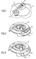
- a domestic pressure cooking appliance of the pressure cooker type comprising, in a manner known per se, a cooking vessel (not shown in the figures) and a lid 2 intended to be attached to the vessel. to form a sealed cooking chamber.
- the seal is obtained by locking the lid 2 on the tank with an annular seal (not shown in the figures) and a locking / unlocking system, to allow the pressure rise of the appliance and cooking the food contained in the appliance.
- the locking / unlocking of the lid 2 on the tank can be of any known type, without limiting the object of the invention, and involve a stirrup system, a tank and lid ramp system or a system comprising radially displaceable jaws or any other equivalent system.
- Domestic pressure cooking appliances concerned by the invention are therefore pressure cookers stirrups, bayonet pressure cookers, pressure cookers with radial displacement or not or pressure cookers said manhole, such a list not being obviously not limiting.
- the pressurized food cooking appliance also comprises a pressure regulating valve 3 equipped with a seal 3A, preferably mounted on the lid 2, such a valve 3 being sensitive to the pressure prevailing in the cooking chamber and being movably mounted between two stable abutment positions, the first in which it closes the communication of the enclosure towards the outside of the apparatus as long as the internal pressure is lower than a predetermined pressure P 0 , the second in which it communicates the inside of the chamber with the outside of the device by a steam outlet as soon as the internal pressure substantially reaches the predetermined pressure P 0 .
- the pressure P 0 will be chosen as the normal cooking pressure of the pressure cooker.
- Such devices are well known to those skilled in the art and are intended to achieve a regulation of the cooking pressure which must be maintained below a predetermined threshold P 0 , value from which the valve 3 ensures a vapor leakage. regulating the internal pressure of the pressure cooker.
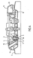
- valve 3 may advantageously be a weight or compression spring valve movably mounted in a well 4 between a stable stop position illustrated in FIG. figure 4 in which it rests under its own weight on a seat 5 formed through a bore 6 of the lid 2.
- the valve 3 can also occupy a high abutment position (not shown in the figures) under the effect of the internal operating pressure of the pressure cooker, when the latter reaches or exceeds the predetermined value P 0 of operation. In this position, the valve 3 rises and disengages the orifice 5 through which the steam can escape to the outside, through the bore 6 by a steam outlet 7, located immediately or in the immediate vicinity of said piercing .
- valve 3 may be provided with a calibration system allowing the user to select a predetermined cooking pressure P 0 from a choice of two or more pressure levels. depending on the type of food present in the pressure cooker.
- the pressurized food cooking appliance is provided with a temperature sensor 10 which is arranged in the vicinity of the outlet 7, to enable the temperature increase resulting from the passage of the steam to be sensed. through the steam outlet 7.
- the temperature sensor 10 may be disposed in the immediate vicinity of the outlet 7 or at a distance, of the order of a few centimeters for example, as soon as the temperature variation can be detected sufficiently clearly and sensitively.
- the positioning distance may also be usefully determined by those skilled in the art depending on the sensitivity of the sensor 10 used.
- the temperature sensor 10 will advantageously be functionally connected to a timer 11, so as to ensure that it is triggered as soon as the increase in temperature is sensed.
- the sensor 10 used may advantageously be a CTN type sensor operatively connected by a suitable connection 12 and via timer processing electronics 11.
- the timer 11 and the temperature sensor 10 will be mounted on the lid 2 of the pressure cooker.
- the steam outlet is formed by a conduit 13 beginning downstream of the valve 3 near the outlet 7 and opening out of the apparatus.
- the temperature sensor 10 is mounted outside the duct 13 and for example bears against the outer surface of the walls of the duct 13.
- the sensor 10 could nevertheless be mounted inside the duct 13 (FIG. figure 1 ).
- the duct 13 as well as the temperature sensor 10 may be pre-assembled and form part of a unitary unitary unit, integrated directly into a plate 15 intended to be placed on the lid 2.
- the timer 11 will advantageously be a removable timer that the user can extract from the pressure cooker to keep on or near him.
- This feature allows the user, from the automatic trigger of the timer 11 via the sensor 10 disposed in the pressure control heat flow, signaled for example by a sound signal, to extract the timer 11 and monitor the evolution of the cooking time at a distance from the appliance. This at the same time allows the user to adjust the cooking level as soon as the predetermined cooking pressure is reached, while recovering the timer 11.
- the pressure cooker will be provided with a housing 16 for receiving the timer 11.
- the housing 16 may also, alternatively, be formed in a plate 15 independent.
- the timer 11 will be provided with an LCD 17 for reading information, including temperatures and time, and buttons 18 for making various settings, such as cooking time for example.
- the timer 11 will also be provided with female connectors (not shown) intended to come into contact with male connectors 20 connected to the connector 12 and arranged in the housing 16 to provide the electrical connection with the sensor 10.
- the temperature sensor 10 may be connected to an organ other than a timer, and for example to a safety device, signaling, for example sonically, the achievement of a predetermined critical pressure or a critical predetermined temperature.
- the user locks the lid 2 on the tank and initializes the timer 11 by putting it in its waking position, so that it can detect a rise in temperature.
- the trigger threshold of the temperature sensor could for example be preset at the factory, to a value of the order of 50 ° C, the temperature from which the sensor 10 sends a count signal from time to timer 11.
- the timer 11 is in the waking position and the pressure cooker locked, the rise in temperature can begin. As soon as the predetermined operating pressure of cooking is reached, the valve 3 releases a stream of vapor, which causes a sudden rise in temperature in the duct 13, the temperature rise which is detected by the sensor 10. This last sends a temperature detection signal to the timer 11 which emits a signal, for example sound, warning the user.
- the latter can then remove the timer 11, perform various operations such as stopping the ring, enter the required cooking time if the user has not previously entered the timer or change the cooking time previously already entered, etc., while taking the timer 11 with him.
- the latter is again informed by the timer by an audible signal and / or by a blinking signal of the digital display 17.
- the parameterization of the temperature detection can be advantageously improved by means of a logic diagram providing, for security reasons, detection of a lower temperature threshold of 45 ° C., the logic diagram containing the information necessary to systematically add a constant value of 5 ° for example the temperature value read, so as to be certain to detect the temperature of 50 ° C, which can then be validated or not by the user, which triggers the countdown time.
- an upper limit value of temperature for example of the order of 75 ° C, can be preprogrammed, maximum threshold temperature from which the countdown of time is systematically validated and engaged.
- the device according to the invention consequently makes it possible to detect, in a particularly reliable and reliable way, the beginning of cooking in a pressure cooker, regardless of the pressure value in the cooking chamber.
- the invention therefore relates accordingly to a method of controlling the cooking cycle of a pressure cooking appliance of the pressure cooker type, provided or not directly with heating elements, in which the temperature of the steam flow is used. escaping from the device's pressure regulating valve to trigger a timer mounted on the device. This use of the temperature of the vapor flow is carried out by detecting, with the aid of a suitable temperature sensor, the sudden rise in temperature which is generated by the sudden escape of steam as soon as the operating pressure of the steam is reached. device is reached.
- the latter emits a warning signal, for example light or sound or other, to warn the user of its trigger.
- a warning signal for example light or sound or other
- the timer being removably mounted on the cooking appliance, the timer is physically separated or separated from the appliance, and the appliance is then monitored remotely. evolution of cooking by consultation, including visual timer.
- the removable mounting of the timer allows the user to take the timer with him as soon as or after its release, and thus move away from the cooking appliance in operation. This allows the user to monitor and control the evolution of cooking by being at a distance and in a spatial location entirely separate from the apparatus.
- the timer then emits a warning signal of end of cooking cycle, which allows the user, possibly away from the device, to return to the latter to stop cooking for example.
- the invention finds its industrial application in the manufacture and design of pressure cooking appliances.
Landscapes
- Engineering & Computer Science (AREA)
- Food Science & Technology (AREA)
- Cookers (AREA)
- Measuring Fluid Pressure (AREA)
Claims (14)
- Dampfdruck-Kochgerät mit:- einem Behälter und einem Deckel (2), der dazu bestimmt ist, auf den Behälter aufgesetzt zu werden, un einen dichten Gareinschluss zu bilden,- einem Temperatursensor (10),- einem Druckregelventil (3), das auf den Druck reagiert, der im Inneren des Gareinschlusses herrscht, und das zwischen zwei stabilen Anschlagpositionen beweglich montiert ist, einer ersten, in der es die Kommunikation des Einschlusses mit der Außenseite sperrt, solange der Innendruck niedriger ist als der vorbestimmte Druck P0, einer zweiten, in der es das Innere des Einschlusses mit der Außenseite über einen Dampfausgang (7) in Kommunikation bringt, sobald der Innendruck im Wesentlichen den vorbestimmten Druck P0 erreicht,dadurch gekenntzeichnet, dass der Temperatursensor (10) in der Nähe des Ausgangs (7) angeordnet ist, um das Erfassen des Temperaturanstiegs zu erlauben, der sich durch die Passage des Dampfs durch den Dampfausgang (7) ergibt, und funktional mit einem Zeitmesser (11) oder einer Sicherheitsvorrichtung derart verbunden ist, dass sein Auslösen ab dem Erfassen des Temperaturanstiegs sichergestellt ist.
- Gerät nach Anspruch 1, dadurch gekennzeichnet, dass der Zeitmesser (11) und der Temperatursensor (10) auf den Behälter oder auf dem Deckel (2) montiert sind.
- Gerät nach Anspruch 2, dadurch gekennzeichnet, dass der Zeitmesser (11) abnehmbar ist.
- Gerät nach einem der Ansprüche 1 bis 3, dadurch gekennzeichnet, dass der Zeitmesser (11) funktionalmit dem Temperatursensor (10) über elektrische Stecker (20) verbunden ist.
- Gerät nach einem der Ansprüche 1 bis 4, dadurch gekennzeichnet, dass der Dampfausgang (7) aus einer Leitung (13) gebildet wird, die stromabwärts des Ventils (3) beginnt.
- Gerät nach Anspruch 5, dadurch gekennzeichnet, dass die Leitung (13) und der Temperatursensor (10) aus einem Stück gebildet sind.
- Gerät nach Anspruch 5, dadurch gekennzeichnet, dass der Temperatursensor (10) außerhalb der Leitung (13) montiert ist.
- Gerät nach Anspruch 7, dadurch gekennzeichnet, dass der Temperatursensor (10) gegen die Außenfläche der Leitung (13) montiert ist.
- Gerät nach einem der vorhergehenden Ansprüche, dadurch gekennzeichnet, dass es aus einem Schnellkochtopf besteht.
- Abnehmbarer Zeitmesser (11), der dazu bestimmt ist, verwendet zu werden für und abnehmbar montiert zu werden auf ein Dampfdruck-Kochgerät für Nahrungsmittel, umfassend:1 einen Behälter und einen Deckel (2), der dazu bestimmt ist, auf den Behälter aufgesetzt zu werden, um einen dichten Gareinschluss zu bilden,2 einen Temperatursensor (10),3 ein Druckregelventil (3), das auf den Druck reagiert, der in dem Gareinschluss herrscht und das zwischen zwei stabilen Anschlagpositionen beweglich montiert ist, einer ersten, in der es die Kommunikation des Einschlusses mit der Außenweite solange sperrt, solange der Innendruck niedriger ist als der vorbestimmte Druck P0, einer zweiten, in der es das Innere des Einschlusses mit der Außenseite über einen Dampfausgang (7) in Kommunikation bringt, sobald der Innendruck im Wesentlichen den vorbestimmten Druck P0 erreicht, wobei der Temperatursensor (10) in der Nähe des Ausgangs (7) angeordnet ist, um das Erfassen des Temperaturanstiegs zu erlauben, der sich aus der Passage des Dampfs durch den Dampfausgang (7) ergibt, und funktional mit dem abnehmbaren Zeitmesser (11) derart verbunden, dass dessen Auslösen sichergestellt wird, sobald der Temperaturanstieg erfasst wird, wobei der abnehmbare Zeitmesser (11) ein Warnsignal abgibt, um den Benutzer über sein Auslösen zu informieren und es dem Benutzter zu erlauben, den Zeitmesser (11) abzunehmen.
- Verfahren zum Steuern des Garzyklus eines Dampfdruck-Kochgeräts, bei dem man die Temperatur des Dampfstroms verwendet, der aus dem Druckregelventil des Geräts austritt, um das automatische Auslösen eines Zeitmessers, der auf das Gerät montiert ist, sicherzustellen, das ein Warnsignal abgibt, um den Benutzer in Echtzeit über das Erreichen des Betriebsdrucks zu einformieren.
- Verfahren nach Anspruch 11, dadurch gekennzeichnet, dass gleichzeitig mit dem Auslösen des Zeitmessers oder der Sicherheitsvorrichtung dieser/diese Letztere ein Warnsignal abgibt, zum Beispiel ein Lichtsignal oder akustisches Signal, um den Benutzer zu warnen.
- Verfahren nach Anspruch 10 oder 11, dadurch gekennzeichnet, dass man, da der Zeitmesser abnehmbar auf das Gerät montiert ist, der Zeitmesser von dem Gerät entfernt und dann in einem Abstand die Entwicklung des Garens durch Ablesen des Zeitmessers überwacht.
- Verfahren nach Anspruch 13, dadurch gekennzeichnet, dass der Zeitmesser am Ende des Garzyklus ein Warnsignal abgibt.
Applications Claiming Priority (3)
| Application Number | Priority Date | Filing Date | Title |
|---|---|---|---|
| FR0117101A FR2834193B1 (fr) | 2001-12-27 | 2001-12-27 | Appareil de cuisson d'aliments sous pression comportant un capteur de temperature |
| FR0117101 | 2001-12-27 | ||
| PCT/FR2002/004534 WO2003055365A2 (fr) | 2001-12-27 | 2002-12-23 | Appareil de cuisson d'aliments sous pression comportant un capteur de temperature |
Publications (2)
| Publication Number | Publication Date |
|---|---|
| EP1458268A2 EP1458268A2 (de) | 2004-09-22 |
| EP1458268B1 true EP1458268B1 (de) | 2010-09-01 |
Family
ID=8871107
Family Applications (1)
| Application Number | Title | Priority Date | Filing Date |
|---|---|---|---|
| EP02799113A Expired - Lifetime EP1458268B1 (de) | 2001-12-27 | 2002-12-23 | Dampfdruck-kochgerät mit temperatursensor |
Country Status (8)
| Country | Link |
|---|---|
| US (1) | US7451692B2 (de) |
| EP (1) | EP1458268B1 (de) |
| AT (1) | ATE479367T1 (de) |
| AU (1) | AU2002364338A1 (de) |
| DE (2) | DE60237540D1 (de) |
| ES (1) | ES2351850T3 (de) |
| FR (1) | FR2834193B1 (de) |
| WO (1) | WO2003055365A2 (de) |
Families Citing this family (32)
| Publication number | Priority date | Publication date | Assignee | Title |
|---|---|---|---|---|
| KR200353218Y1 (ko) * | 2004-02-05 | 2004-06-22 | 이동우 | 압력용기 밀폐기구 |
| FR2940900B1 (fr) | 2009-01-15 | 2012-01-06 | Seb Sa | Autocuiseur muni d'un dispositif electronique d'information |
| FR2940899B1 (fr) | 2009-01-15 | 2011-02-25 | Seb Sa | Appareil de cuisson a cuisson sequentielle, systeme et procede afferents |
| US9237608B2 (en) | 2009-08-14 | 2016-01-12 | Cem Corporation | Pressure stepped microwave assisted digestion |
| DE102010010498B4 (de) * | 2010-03-06 | 2013-06-13 | Wmf Württembergische Metallwarenfabrik Ag | Dampfkochgefäß |
| FR2957505B1 (fr) * | 2010-03-19 | 2013-03-01 | Seb Sa | Appareil de cuisson d'aliments sous pression avec dosage du liquide de cuisson, doseur et procede de cuisson afferent |
| WO2013190572A1 (en) | 2012-06-22 | 2013-12-27 | Antony Merina Benny | Obtained from the extract of costus pictus d.don plant and method of preparing the same |
| KR102059197B1 (ko) * | 2013-03-22 | 2019-12-24 | 김경희 | 요리 완료를 경보하는 자동 요리 냄비 |
| FR3016118B1 (fr) * | 2014-01-07 | 2016-02-05 | Seb Sa | Systeme de cuisson modulaire et procede afferent |
| FR3016117B1 (fr) | 2014-01-07 | 2016-02-05 | Seb Sa | Systeme de cuisson a utilisation assistee |
| FR3020564B1 (fr) | 2014-04-30 | 2016-06-03 | Seb Sa | Ensemble electronique d'information du fonctionnement d'appareils electromenagers |
| FR3023999B1 (fr) | 2014-07-17 | 2017-10-27 | Seb Sa | Systeme d'assistance a l'utilisation d'un appareil electromenager |
| FR3036938B1 (fr) | 2015-06-04 | 2017-07-14 | Seb Sa | Autocuiseur equipe d'un support et d'un couvercle mobile relativement audit support |
| FR3036939B1 (fr) | 2015-06-04 | 2017-07-14 | Seb Sa | Autocuiseur pourvu d'une soupape demontable et d'un capteur de temperature |
| US10588443B2 (en) * | 2016-03-04 | 2020-03-17 | CE Brands, LLC | Smart slow cooker |
| CN107203153A (zh) * | 2017-07-04 | 2017-09-26 | 谢勇 | 设有活动传感器的电热器具 |
| CN110200516A (zh) | 2017-08-09 | 2019-09-06 | 沙克忍者运营有限责任公司 | 烹饪系统 |
| WO2019075455A1 (en) * | 2017-10-13 | 2019-04-18 | National Presto Industries, Inc. | DIGITAL CONTROL PRESSURE ELECTRONIC PRESERVATION DEVICE |
| CN109696196B (zh) * | 2017-10-24 | 2024-11-19 | 浙江绍兴苏泊尔生活电器有限公司 | 烹饪器具及其检测方法和装置、存储介质、处理器 |
| JP7065327B2 (ja) * | 2018-05-15 | 2022-05-12 | パナソニックIpマネジメント株式会社 | 圧力式調理器及び圧力センサユニット |
| USD914436S1 (en) | 2018-06-19 | 2021-03-30 | Sharkninja Operating Llc | Air diffuser with food preparation pot |
| USD903413S1 (en) | 2018-08-09 | 2020-12-01 | Sharkninja Operating Llc | Cooking basket |
| USD883014S1 (en) | 2018-08-09 | 2020-05-05 | Sharkninja Operating Llc | Food preparation device |
| USD934027S1 (en) | 2018-08-09 | 2021-10-26 | Sharkninja Operating Llc | Reversible cooking rack |
| USD883015S1 (en) | 2018-08-09 | 2020-05-05 | Sharkninja Operating Llc | Food preparation device and parts thereof |
| CN110934486B (zh) * | 2018-09-25 | 2022-06-28 | 浙江绍兴苏泊尔生活电器有限公司 | 烹饪器具及其上压温度处理方法和装置 |
| WO2020176477A1 (en) | 2019-02-25 | 2020-09-03 | Sharkninja Operating Llc | Cooking system with guard |
| US11033146B2 (en) | 2019-02-25 | 2021-06-15 | Sharkninja Operating Llc | Cooking device and components thereof |
| USD982375S1 (en) | 2019-06-06 | 2023-04-04 | Sharkninja Operating Llc | Food preparation device |
| USD918654S1 (en) | 2019-06-06 | 2021-05-11 | Sharkninja Operating Llc | Grill plate |
| US11647861B2 (en) | 2020-03-30 | 2023-05-16 | Sharkninja Operating Llc | Cooking device and components thereof |
| CN112656245B (zh) * | 2020-12-31 | 2023-11-17 | 广东美的厨房电器制造有限公司 | 烹饪器具、烹饪器具的控制方法和可读存储介质 |
Family Cites Families (9)
| Publication number | Priority date | Publication date | Assignee | Title |
|---|---|---|---|---|
| GB2061760B (en) * | 1979-10-24 | 1983-06-08 | Redring Electric Ltd | Pressure cookers |
| DE2949890A1 (de) | 1979-12-12 | 1981-06-19 | Diehl GmbH & Co, 8500 Nürnberg | Verfahren zur ueberwachung des garens von speisen in einem dampfdruckkochkopf und vorrichtung zur durchfuehrung des verfahrens |
| FR2634914A1 (fr) | 1988-08-01 | 1990-02-02 | Terraillon | Dispositif electronique de controle pour autocuiseur |
| US5271893A (en) * | 1989-11-24 | 1993-12-21 | Duncan Newman | Apparatus for steam sterilization of articles |
| US5048400A (en) * | 1989-12-22 | 1991-09-17 | Matsushita Electric Industrial Co., Ltd. | Pressure cooker with sensor |
| ES1014675Y (es) * | 1990-07-05 | 1992-01-01 | Fagor, S.Coop. Ltda. | Avisador acustico para ollas a presion. |
| US5567458A (en) * | 1995-02-02 | 1996-10-22 | Wu; James M. | Method and apparatus for automatic adiabatic cooking |
| KR20000009543A (ko) * | 1998-07-25 | 2000-02-15 | 구자신 | 전기압력보온밥솥과 그의 요리 제어 방법 |
| US6070518A (en) * | 2000-01-07 | 2000-06-06 | Kao; Yao-Tzong | Pressure cooker |
-
2001
- 2001-12-27 FR FR0117101A patent/FR2834193B1/fr not_active Expired - Fee Related
-
2002
- 2002-12-23 DE DE60237540T patent/DE60237540D1/de not_active Expired - Lifetime
- 2002-12-23 AT AT02799113T patent/ATE479367T1/de not_active IP Right Cessation
- 2002-12-23 DE DE20220590U patent/DE20220590U1/de not_active Expired - Lifetime
- 2002-12-23 EP EP02799113A patent/EP1458268B1/de not_active Expired - Lifetime
- 2002-12-23 ES ES02799113T patent/ES2351850T3/es not_active Expired - Lifetime
- 2002-12-23 WO PCT/FR2002/004534 patent/WO2003055365A2/fr not_active Ceased
- 2002-12-23 AU AU2002364338A patent/AU2002364338A1/en not_active Abandoned
- 2002-12-23 US US10/500,163 patent/US7451692B2/en not_active Expired - Fee Related
Also Published As
| Publication number | Publication date |
|---|---|
| US20050028678A1 (en) | 2005-02-10 |
| WO2003055365A3 (fr) | 2004-02-12 |
| AU2002364338A1 (en) | 2003-07-15 |
| DE60237540D1 (de) | 2010-10-14 |
| WO2003055365A2 (fr) | 2003-07-10 |
| FR2834193A1 (fr) | 2003-07-04 |
| ES2351850T3 (es) | 2011-02-11 |
| ATE479367T1 (de) | 2010-09-15 |
| FR2834193B1 (fr) | 2004-04-09 |
| DE20220590U1 (de) | 2003-11-27 |
| EP1458268A2 (de) | 2004-09-22 |
| US7451692B2 (en) | 2008-11-18 |
Similar Documents
| Publication | Publication Date | Title |
|---|---|---|
| EP1458268A2 (de) | Dampfdruck-kochgerät mit temperatursensor | |
| EP2898800B1 (de) | Modulares Kochsystem und entsprechendes Verfahren | |
| EP3100656B1 (de) | Schnellkochtopf mit einer unterstützung und einem bewegbaren deckel | |
| EP2387338B1 (de) | Schnellkochtopf mit elektronischer informationsvorrichtung | |
| EP1342440B1 (de) | Dampfdruck-Kochgerät mit einem Deckelmodul | |
| EP1277427B1 (de) | Dampfdruck-Kochtopf mit einem kalibrierten Entlüftungsventil | |
| EP1535552B1 (de) | Dampfdruckkochgerät | |
| EP2208448B1 (de) | Kochgerät mit abwechselnder Anwendung, System und Verfahren | |
| EP2939574B1 (de) | Elektronische einheit zur information über den betrieb von elektrohaushaltsgeräten | |
| EP0843039B1 (de) | Dampferzeuger | |
| EP3273831B1 (de) | Mit einem kochbehältererkennungssystem ausgestattete kochverwaltungsvorrichtung | |
| WO2016009138A1 (fr) | Système d'assistance a l'utilisation d'un appareil électroménager | |
| WO2005053480A1 (fr) | Appareil de cuisson sous pression comportant un moyen de securite a l’ouverture | |
| FR2634914A1 (fr) | Dispositif electronique de controle pour autocuiseur | |
| FR2899453A1 (fr) | Appareil de cuisson sous pression a decompression maitrisee | |
| FR2945608A1 (fr) | Procede et systeme de controle de la temperature d'une cuisson. | |
| EP1844685B1 (de) | Druckkochgerät mit verstellbarem Sollwert und überwachter Dekompression | |
| FR2706050A1 (fr) | Dispositif de commande programmable pour autocuiseur, à pression contrôlée. | |
| EP1420673B1 (de) | Gerät zur zubereitung von nahrungsmitteln, insbesondere friteuse, mit einem katalysator und mitteln zur einstellung des katalysators | |
| FR2633482A1 (fr) | Recipient culinaire, procede et dispositif de regulation thermique du chauffage de ce recipient | |
| JP6735548B2 (ja) | 圧力フライヤー | |
| EP1794455A1 (de) | Verfahren für den elektrischen schutz eines elektrohaushaltsgeräts | |
| FR3003339A1 (fr) | Procede pour le recyclage et le chauffage d'eau sanitaire au moyen d'un dispositif de recirculation et de chauffage | |
| FR2913098A1 (fr) | Table de cuisson et procede de surveillance anti-debordement d'un liquide associe | |
| FR2512933A1 (fr) | Dispositif de securite pour appareil de chauffage mobile tel que poele a petrole |
Legal Events
| Date | Code | Title | Description |
|---|---|---|---|
| PUAI | Public reference made under article 153(3) epc to a published international application that has entered the european phase |
Free format text: ORIGINAL CODE: 0009012 |
|
| 17P | Request for examination filed |
Effective date: 20040713 |
|
| AK | Designated contracting states |
Kind code of ref document: A2 Designated state(s): AT BE BG CH CY CZ DE DK EE ES FI FR GB GR IE IT LI LU MC NL PT SE SI SK TR |
|
| AX | Request for extension of the european patent |
Extension state: AL LT LV MK RO |
|
| 17Q | First examination report despatched |
Effective date: 20060323 |
|
| GRAP | Despatch of communication of intention to grant a patent |
Free format text: ORIGINAL CODE: EPIDOSNIGR1 |
|
| GRAS | Grant fee paid |
Free format text: ORIGINAL CODE: EPIDOSNIGR3 |
|
| GRAA | (expected) grant |
Free format text: ORIGINAL CODE: 0009210 |
|
| AK | Designated contracting states |
Kind code of ref document: B1 Designated state(s): AT BE BG CH CY CZ DE DK EE ES FI FR GB GR IE IT LI LU MC NL PT SE SI SK TR |
|
| REG | Reference to a national code |
Ref country code: GB Ref legal event code: FG4D Free format text: NOT ENGLISH |
|
| REG | Reference to a national code |
Ref country code: CH Ref legal event code: EP |
|
| REG | Reference to a national code |
Ref country code: IE Ref legal event code: FG4D Free format text: LANGUAGE OF EP DOCUMENT: FRENCH |
|
| REF | Corresponds to: |
Ref document number: 60237540 Country of ref document: DE Date of ref document: 20101014 Kind code of ref document: P |
|
| REG | Reference to a national code |
Ref country code: NL Ref legal event code: VDEP Effective date: 20100901 |
|
| PG25 | Lapsed in a contracting state [announced via postgrant information from national office to epo] |
Ref country code: FI Free format text: LAPSE BECAUSE OF FAILURE TO SUBMIT A TRANSLATION OF THE DESCRIPTION OR TO PAY THE FEE WITHIN THE PRESCRIBED TIME-LIMIT Effective date: 20100901 Ref country code: AT Free format text: LAPSE BECAUSE OF FAILURE TO SUBMIT A TRANSLATION OF THE DESCRIPTION OR TO PAY THE FEE WITHIN THE PRESCRIBED TIME-LIMIT Effective date: 20100901 |
|
| REG | Reference to a national code |
Ref country code: ES Ref legal event code: FG2A Effective date: 20110201 |
|
| PG25 | Lapsed in a contracting state [announced via postgrant information from national office to epo] |
Ref country code: CY Free format text: LAPSE BECAUSE OF FAILURE TO SUBMIT A TRANSLATION OF THE DESCRIPTION OR TO PAY THE FEE WITHIN THE PRESCRIBED TIME-LIMIT Effective date: 20100901 Ref country code: SI Free format text: LAPSE BECAUSE OF FAILURE TO SUBMIT A TRANSLATION OF THE DESCRIPTION OR TO PAY THE FEE WITHIN THE PRESCRIBED TIME-LIMIT Effective date: 20100901 |
|
| REG | Reference to a national code |
Ref country code: IE Ref legal event code: FD4D |
|
| PG25 | Lapsed in a contracting state [announced via postgrant information from national office to epo] |
Ref country code: GR Free format text: LAPSE BECAUSE OF FAILURE TO SUBMIT A TRANSLATION OF THE DESCRIPTION OR TO PAY THE FEE WITHIN THE PRESCRIBED TIME-LIMIT Effective date: 20101202 Ref country code: SE Free format text: LAPSE BECAUSE OF FAILURE TO SUBMIT A TRANSLATION OF THE DESCRIPTION OR TO PAY THE FEE WITHIN THE PRESCRIBED TIME-LIMIT Effective date: 20100901 Ref country code: NL Free format text: LAPSE BECAUSE OF FAILURE TO SUBMIT A TRANSLATION OF THE DESCRIPTION OR TO PAY THE FEE WITHIN THE PRESCRIBED TIME-LIMIT Effective date: 20100901 |
|
| PG25 | Lapsed in a contracting state [announced via postgrant information from national office to epo] |
Ref country code: IE Free format text: LAPSE BECAUSE OF FAILURE TO SUBMIT A TRANSLATION OF THE DESCRIPTION OR TO PAY THE FEE WITHIN THE PRESCRIBED TIME-LIMIT Effective date: 20100901 |
|
| PG25 | Lapsed in a contracting state [announced via postgrant information from national office to epo] |
Ref country code: SK Free format text: LAPSE BECAUSE OF FAILURE TO SUBMIT A TRANSLATION OF THE DESCRIPTION OR TO PAY THE FEE WITHIN THE PRESCRIBED TIME-LIMIT Effective date: 20100901 Ref country code: PT Free format text: LAPSE BECAUSE OF FAILURE TO SUBMIT A TRANSLATION OF THE DESCRIPTION OR TO PAY THE FEE WITHIN THE PRESCRIBED TIME-LIMIT Effective date: 20110103 Ref country code: EE Free format text: LAPSE BECAUSE OF FAILURE TO SUBMIT A TRANSLATION OF THE DESCRIPTION OR TO PAY THE FEE WITHIN THE PRESCRIBED TIME-LIMIT Effective date: 20100901 Ref country code: CZ Free format text: LAPSE BECAUSE OF FAILURE TO SUBMIT A TRANSLATION OF THE DESCRIPTION OR TO PAY THE FEE WITHIN THE PRESCRIBED TIME-LIMIT Effective date: 20100901 |
|
| PLBE | No opposition filed within time limit |
Free format text: ORIGINAL CODE: 0009261 |
|
| STAA | Information on the status of an ep patent application or granted ep patent |
Free format text: STATUS: NO OPPOSITION FILED WITHIN TIME LIMIT |
|
| PG25 | Lapsed in a contracting state [announced via postgrant information from national office to epo] |
Ref country code: MC Free format text: LAPSE BECAUSE OF NON-PAYMENT OF DUE FEES Effective date: 20101231 |
|
| REG | Reference to a national code |
Ref country code: CH Ref legal event code: PL |
|
| 26N | No opposition filed |
Effective date: 20110606 |
|
| PG25 | Lapsed in a contracting state [announced via postgrant information from national office to epo] |
Ref country code: DK Free format text: LAPSE BECAUSE OF FAILURE TO SUBMIT A TRANSLATION OF THE DESCRIPTION OR TO PAY THE FEE WITHIN THE PRESCRIBED TIME-LIMIT Effective date: 20100901 |
|
| REG | Reference to a national code |
Ref country code: DE Ref legal event code: R097 Ref document number: 60237540 Country of ref document: DE Effective date: 20110606 |
|
| PG25 | Lapsed in a contracting state [announced via postgrant information from national office to epo] |
Ref country code: CH Free format text: LAPSE BECAUSE OF NON-PAYMENT OF DUE FEES Effective date: 20101231 Ref country code: LI Free format text: LAPSE BECAUSE OF NON-PAYMENT OF DUE FEES Effective date: 20101231 |
|
| PG25 | Lapsed in a contracting state [announced via postgrant information from national office to epo] |
Ref country code: LU Free format text: LAPSE BECAUSE OF NON-PAYMENT OF DUE FEES Effective date: 20101223 Ref country code: BG Free format text: LAPSE BECAUSE OF FAILURE TO SUBMIT A TRANSLATION OF THE DESCRIPTION OR TO PAY THE FEE WITHIN THE PRESCRIBED TIME-LIMIT Effective date: 20100901 |
|
| PG25 | Lapsed in a contracting state [announced via postgrant information from national office to epo] |
Ref country code: BG Free format text: LAPSE BECAUSE OF FAILURE TO SUBMIT A TRANSLATION OF THE DESCRIPTION OR TO PAY THE FEE WITHIN THE PRESCRIBED TIME-LIMIT Effective date: 20101201 |
|
| REG | Reference to a national code |
Ref country code: FR Ref legal event code: PLFP Year of fee payment: 14 |
|
| REG | Reference to a national code |
Ref country code: FR Ref legal event code: PLFP Year of fee payment: 15 |
|
| REG | Reference to a national code |
Ref country code: FR Ref legal event code: CA Effective date: 20170518 |
|
| REG | Reference to a national code |
Ref country code: FR Ref legal event code: PLFP Year of fee payment: 16 |
|
| PGFP | Annual fee paid to national office [announced via postgrant information from national office to epo] |
Ref country code: GB Payment date: 20181031 Year of fee payment: 10 |
|
| REG | Reference to a national code |
Ref country code: BE Ref legal event code: MM Effective date: 20191231 |
|
| GBPC | Gb: european patent ceased through non-payment of renewal fee |
Effective date: 20191223 |
|
| PG25 | Lapsed in a contracting state [announced via postgrant information from national office to epo] |
Ref country code: GB Free format text: LAPSE BECAUSE OF NON-PAYMENT OF DUE FEES Effective date: 20191223 |
|
| PG25 | Lapsed in a contracting state [announced via postgrant information from national office to epo] |
Ref country code: BE Free format text: LAPSE BECAUSE OF NON-PAYMENT OF DUE FEES Effective date: 20191231 |
|
| PGFP | Annual fee paid to national office [announced via postgrant information from national office to epo] |
Ref country code: DE Payment date: 20211210 Year of fee payment: 20 Ref country code: TR Payment date: 20211208 Year of fee payment: 20 Ref country code: FR Payment date: 20211230 Year of fee payment: 20 |
|
| PGFP | Annual fee paid to national office [announced via postgrant information from national office to epo] |
Ref country code: IT Payment date: 20211213 Year of fee payment: 20 |
|
| PGFP | Annual fee paid to national office [announced via postgrant information from national office to epo] |
Ref country code: ES Payment date: 20220104 Year of fee payment: 20 |
|
| REG | Reference to a national code |
Ref country code: DE Ref legal event code: R071 Ref document number: 60237540 Country of ref document: DE |
|
| REG | Reference to a national code |
Ref country code: ES Ref legal event code: FD2A Effective date: 20230428 |
|
| PG25 | Lapsed in a contracting state [announced via postgrant information from national office to epo] |
Ref country code: ES Free format text: LAPSE BECAUSE OF EXPIRATION OF PROTECTION Effective date: 20221224 |