EP1458509B1 - Vorrichtung zur herstellung von metallgussteilen - Google Patents
Vorrichtung zur herstellung von metallgussteilen Download PDFInfo
- Publication number
- EP1458509B1 EP1458509B1 EP02793071A EP02793071A EP1458509B1 EP 1458509 B1 EP1458509 B1 EP 1458509B1 EP 02793071 A EP02793071 A EP 02793071A EP 02793071 A EP02793071 A EP 02793071A EP 1458509 B1 EP1458509 B1 EP 1458509B1
- Authority
- EP
- European Patent Office
- Prior art keywords
- metal
- mold
- inlets
- control unit
- cavity
- Prior art date
- Legal status (The legal status is an assumption and is not a legal conclusion. Google has not performed a legal analysis and makes no representation as to the accuracy of the status listed.)
- Expired - Lifetime
Links
- 238000005058 metal casting Methods 0.000 title claims abstract description 11
- 239000002184 metal Substances 0.000 claims abstract description 65
- 229910052751 metal Inorganic materials 0.000 claims abstract description 64
- 238000005086 pumping Methods 0.000 claims abstract description 14
- 238000000465 moulding Methods 0.000 claims abstract 2
- 238000010438 heat treatment Methods 0.000 claims description 10
- 238000009826 distribution Methods 0.000 claims description 7
- 238000005259 measurement Methods 0.000 claims description 6
- 239000000919 ceramic Substances 0.000 claims description 3
- 230000006698 induction Effects 0.000 claims description 3
- 238000011144 upstream manufacturing Methods 0.000 claims description 2
- 238000009529 body temperature measurement Methods 0.000 claims 1
- 238000000034 method Methods 0.000 abstract description 8
- 238000005266 casting Methods 0.000 description 20
- 230000015572 biosynthetic process Effects 0.000 description 8
- 238000007711 solidification Methods 0.000 description 6
- 230000008023 solidification Effects 0.000 description 6
- 229910045601 alloy Inorganic materials 0.000 description 5
- 239000000956 alloy Substances 0.000 description 5
- 238000004519 manufacturing process Methods 0.000 description 4
- 239000007789 gas Substances 0.000 description 3
- 239000000463 material Substances 0.000 description 3
- 229910052782 aluminium Inorganic materials 0.000 description 2
- XAGFODPZIPBFFR-UHFFFAOYSA-N aluminium Chemical compound [Al] XAGFODPZIPBFFR-UHFFFAOYSA-N 0.000 description 2
- 238000004512 die casting Methods 0.000 description 2
- 238000002347 injection Methods 0.000 description 2
- 239000007924 injection Substances 0.000 description 2
- 229910001234 light alloy Inorganic materials 0.000 description 2
- 230000033001 locomotion Effects 0.000 description 2
- LLQHSBBZNDXTIV-UHFFFAOYSA-N 6-[5-[[4-[2-(2,3-dihydro-1H-inden-2-ylamino)pyrimidin-5-yl]piperazin-1-yl]methyl]-4,5-dihydro-1,2-oxazol-3-yl]-3H-1,3-benzoxazol-2-one Chemical compound C1C(CC2=CC=CC=C12)NC1=NC=C(C=N1)N1CCN(CC1)CC1CC(=NO1)C1=CC2=C(NC(O2)=O)C=C1 LLQHSBBZNDXTIV-UHFFFAOYSA-N 0.000 description 1
- QVGXLLKOCUKJST-UHFFFAOYSA-N atomic oxygen Chemical compound [O] QVGXLLKOCUKJST-UHFFFAOYSA-N 0.000 description 1
- 238000009749 continuous casting Methods 0.000 description 1
- 238000001816 cooling Methods 0.000 description 1
- 230000007423 decrease Effects 0.000 description 1
- 230000005484 gravity Effects 0.000 description 1
- 230000002706 hydrostatic effect Effects 0.000 description 1
- 239000007788 liquid Substances 0.000 description 1
- 229910001092 metal group alloy Inorganic materials 0.000 description 1
- 238000012986 modification Methods 0.000 description 1
- 230000004048 modification Effects 0.000 description 1
- 238000013021 overheating Methods 0.000 description 1
- 239000001301 oxygen Substances 0.000 description 1
- 229910052760 oxygen Inorganic materials 0.000 description 1
- 208000026438 poor feeding Diseases 0.000 description 1
- 230000007847 structural defect Effects 0.000 description 1
Images


Classifications
-
- B—PERFORMING OPERATIONS; TRANSPORTING
- B22—CASTING; POWDER METALLURGY
- B22D—CASTING OF METALS; CASTING OF OTHER SUBSTANCES BY THE SAME PROCESSES OR DEVICES
- B22D17/00—Pressure die casting or injection die casting, i.e. casting in which the metal is forced into a mould under high pressure
- B22D17/20—Accessories: Details
- B22D17/30—Accessories for supplying molten metal, e.g. in rations
-
- B—PERFORMING OPERATIONS; TRANSPORTING
- B22—CASTING; POWDER METALLURGY
- B22D—CASTING OF METALS; CASTING OF OTHER SUBSTANCES BY THE SAME PROCESSES OR DEVICES
- B22D35/00—Equipment for conveying molten metal into beds or moulds
- B22D35/04—Equipment for conveying molten metal into beds or moulds into moulds, e.g. base plates, runners
-
- B—PERFORMING OPERATIONS; TRANSPORTING
- B22—CASTING; POWDER METALLURGY
- B22D—CASTING OF METALS; CASTING OF OTHER SUBSTANCES BY THE SAME PROCESSES OR DEVICES
- B22D37/00—Controlling or regulating the pouring of molten metal from a casting melt-holding vessel
-
- B—PERFORMING OPERATIONS; TRANSPORTING
- B22—CASTING; POWDER METALLURGY
- B22D—CASTING OF METALS; CASTING OF OTHER SUBSTANCES BY THE SAME PROCESSES OR DEVICES
- B22D39/00—Equipment for supplying molten metal in rations
- B22D39/02—Equipment for supplying molten metal in rations having means for controlling the amount of molten metal by volume
- B22D39/023—Equipment for supplying molten metal in rations having means for controlling the amount of molten metal by volume using a displacement member
Definitions
- the present invention relates to an apparatus for forming metal castings, particularly with hydraulic connection between the holding furnace and the mold and to a method for forming metal castings performed by the apparatus.
- castings made of metal or light alloys are molded by using pouring processes, such as for example the gravity feeding of the molten metal or alloy into closed molds, and the generation of pressure inside the mold by way of feedheads, which feed the molten casting, increasing the hydrostatic load on the metal or alloy, and prevent the formation of cavities or porosities inside the casting during shrinkage in the solidification step.
- Another method for forming castings by pouring metal or alloys is so-called low-pressure casting, which substantially consists in placing a mold over a closed furnace whose cavity is fed through a riser tube connected to the furnace, inside which pressure is applied to the free surface of the metal so that part of said metal rises through the riser tube and feeds the mold.
- known casting techniques are not always suitable to ensure the formation of castings that are free from structural defects, for example internal tensions and microporosities, especially in the case of the formation of castings having a complex shape, such as wheels of road vehicles made of light alloy and the like.
- the problems are linked, most of all, to poor feeding of the cavity of the mold, especially in the case of castings that have a complex geometry, which generates porosities that can be detected by X-rays as a consequence of the turbulent motions of the metal and of overheating.
- the furnace below the mold is depressurized and because of this operation the column of molten metal inside the riser tube, initially at the level of the mold, returns to the level of the metal that is present inside the furnace.
- Films and oxides are of course entrained by the metal into the mold, forming a non-uniform alloy and detracting from the final quality of the provided casting.
- a gas is injected into the furnace; said gas is usually air, which generates oxides owing to the presence of oxygen.
- the furnace when the metal inside the furnace has been used up, the furnace must be opened to allow to fill it, exposing it fully to contact with air.
- the low-pressure casting process is a substantially discontinuous process, since it entails downtimes in the production step due to the time required to fill the riser tube and to the steps for filling said furnace.
- the problems linked to the furnace are due substantially to the holding times for filling it and to the variation of the internal pressure during said filling.
- EP-A-0 711 616 discloses an apparatus as defined in the preamble of claim 1.
- US-4 408 651 discloses a pumping mechanism for a die-casting machine.
- US-4 595 044 discloses a die-casting apparatus for pumping molten metal.
- US-A-3 800 986 discloses a pumping mechanism as defined in the preamble of claim 1.
- the aim of the present invention is to solve or substantially reduce the problems of known types of apparatus for forming metal castings.
- an object of the invention is to provide an apparatus that comprises a constantly loaded hydraulic connection between the holding furnace and the mold and in which the molten metal never makes contact with the air.
- Another object is to provide an apparatus that eliminates the upward and downward flows of the metal along the riser tube, eliminating the formation of oxides and films of solidified metal.
- Another object is to provide an apparatus that allows safe control of the level of metal that is present under the mold.
- Another object is to provide an apparatus by way of which it is possible to provide a continuous casting cycle, eliminating the downtimes for loading the furnace connected to the riser tube.
- Another object is to provide an apparatus by means of which the molten metal is exposed to air as little as possible, consequently avoiding the formation of oxides.
- Another object is to provide an apparatus that allows to provide metal castings without limitations to the operating pressure except for those dictated by the technological limitations of the apparatus itself
- Another object is to provide an apparatus that offers high productivity.
- Another object is to provide an apparatus that allows better feeding of the cavity of the mold.
- Another object is to provide an apparatus that allows to obtain improved mechanical characteristics of the solidified casting.
- Another object is to provide an apparatus that does not use the pressure of air or gas to move the metal and feed the mold.
- the apparatus performs a method for forming metal castings that consists in:
- an apparatus for forming metal castings is generally designated by the reference numeral 10.
- the apparatus 10 comprises a hydraulic connection between a holding furnace 11, which contains the molten metal ready for forming, and a mold 14, which in turn comprises a duct 36 for connecting the holding furnace 11 to one or more inlets 12 for introducing the metal into a the cavity 13 of the mold 14, said one or more inlets 12 being arranged, in this case, under said mold 14, and pumping means 15, which are interposed between portions of said duct 36, for pumping a controlled quantity of metal through one or more inlets 12 into said cavity 13, said means being connected to and controlled by an electronic control unit 16.
- slot-like inlet 12 which runs continuously and circumferentially over 360 sexagesimal degrees at the lower edge of the cavity 13 of a mold 14, for example for forming a wheel for road vehicles.
- the inlet 12 is formed by a distribution unit 17, which is arranged below the mold 14 and is connected to the upper end of a riser tube 18.
- Induction-type measurement devices 19 for measuring the level of the metal present inside the distribution unit 17 are arranged adjacent and below the inlet 12, at the distribution unit 17, and are connected and managed by the control unit 16, as better described hereinafter.
- the inlets 12 can also be arranged laterally to the mold 14.
- the duct 36 comprises a first portion 20, which extends from the holding furnace 11 and is connected to the pumping means 15, from which a second portion 21 protrudes and leads into a reservoir 22.
- the riser tube 18 rises from the reservoir 22, and the distribution unit 17 is arranged above it.
- the apparatus 10 further comprises devices 23 for heating the molten metal and temperature sensors 24 for sensing the temperature of said metal, which are arranged along the hydraulic connection and are connected to the control unit 16.
- the heating devices 23 are constituted by heating resistors, designated by the same reference numeral, which are arranged inside longitudinally elongated ceramic containers arranged at the pumping means 15, at the first portion 20 and second portion 21 of the duct 36, at the reservoir 22 and at the distribution unit 16.
- the temperature sensors 24 are instead constituted by thermocouples, designated by the same reference numeral, which are also arranged on the apparatus 10, like the heating devices 23.
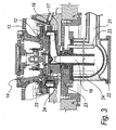
- the pumping means 15 are constituted by a piston pump 25, upstream and downstream of which there are a first valve 26 and a second valve 27 for controlling the flow of metal that flows respectively within said first and second portions 20 and 21 of the duct 36.
- the first and second valves 26 and 27 are designed to provide controlled one-way flow of the metal in the direction from the mold 14 to the holding furnace 11.
- the piston pump 25 comprises a first piston 28, which can slide hermetically in a corresponding first cylinder 29, which is fixed to the head of a first stem 30 of a hydraulic actuator 31, whose stroke is controlled by the control unit 16.
- the first and second valves 26 and 27 are fully identical, and each valve comprises a second piston 32 that can slide hermetically within a corresponding second cylinder 33, which is fixed to the head of a second stem 34 of a corresponding pneumatic actuator 35.
- first valve 26 and the second valve 27 are arranged so as to control respectively the first portion 20 and the second portion 21 of the duct 36 when they are actuated by the control unit 16.
- first valve 26 (like the second valve 27) is arranged between a first part 20a and a second part 20b of the first portion 20 of the duct 36, said parts being arranged with a longitudinal axis at different heights.
- the second piston 32 once lowered, affects the inlet of the second part 20b, whose diameter is smaller than that of the second cylinder 33, and the outlet of the first part 20a, which lies substantially on a horizontal plane and is coaxial to the second piston 32.
- the induction measurement devices 19 can sense temperatures and sense that the level of the metal is close below the inlet 12.
- control unit 16 actuates the advancement of the first cylinder 29 of the piston pump, which allows the injection of the metal into the cavity 13.
- the cycle for forming the casting begins and consists in the steps of filling, feeding, cooling and solidification; said cycle is allowed by the injection of a preset quantity of material into the cavity 13 following the movement of the piston pump 25 actuated by the control unit 16.
- the piston pump 25 continues to feed the cavity 13, keeping the metal under pressure.
- control unit 16 actuates the piston pump 25 so that it retracts with the first cylinder 29, so as to lower the level of the metal with respect to the inlet 12 by a preset value, for example 5-6 mm, making it separate from the casting.
- the mold 14 is opened and the casting is removed, while the level of the aluminum is kept always directly below the inlets 12.
- the piston pump 25 must now be reloaded, and this occurs by drawing back the first stem 30 when the second valve 27 is closed and the first valve 26 is open, drawing metal from the holding furnace 11.
- a plurality of ducts 36 for corresponding molds can be associated with the holding furnace 11 in order to increase the productivity of said apparatus.
- the apparatus 10 is provided with a plurality of heating devices 23, this ensures that the metal always remains liquid, at a temperature that is controlled by the temperature sensors 24.
- the reservoir 22, moreover, is designed to keep the metal at a chosen temperature, which also is determined by heating devices 23 and is measured by the temperature sensors 24.
- the quantity of metal contained in the reservoir is in fact such as to ensure the dissipation of any higher temperatures acquired by the metal in the path from the piston pump 25 to said reservoir 22.
- the purpose of the reservoir 22 is to make the metal or alloy more homogeneous before entering the mold 14.
- An apparatus has in fact been provided which allows to use a hydraulic system that is always loaded, a level of the metal that is always present at the lower level of the mold, with a closed hydraulic circuit that avoids the exposure of the metal to the air, avoiding the formation of oxides.
- the metal injected into the cavity is therefore more homogeneous and allows to obtain a solidified casting whose mechanical characteristics are improved with respect to known apparatuses, using even very high operating pressures.
- the materials may be any according to requirements.
Landscapes
- Engineering & Computer Science (AREA)
- Mechanical Engineering (AREA)
- Molds, Cores, And Manufacturing Methods Thereof (AREA)
- Superconductors And Manufacturing Methods Therefor (AREA)
- Casting Devices For Molds (AREA)
- Manufacture Of Alloys Or Alloy Compounds (AREA)
- Shaping Metal By Deep-Drawing, Or The Like (AREA)
- Processing Of Terminals (AREA)
- Forging (AREA)
Claims (18)
- Vorrichtung zur Herstellung von Metallgussteilen, insbesondere mit hydraulischer Verbindung zwischen dem Warnhalteofen und der Gießform, umfassend:wenigstens einen Kanal (36) zur Verbindung des Warmhalteofens (11), der das für das Formen fertige geschmolzene Metall enthält, zu einem oder mehreren Einlässen (12) zum Einführen des Metalls in die Höhlung (13) einer entsprechenden Gießform (14); undPumpmittel (15), die zwischen Abschnitten (20, 21) des Kanals (36) eingesetzt sind zum Pumpen einer geregelten Menge von Metall durch den einen oder die mehreren Einlässe (12) in die Höhlung (13), wobei die Pumpmittel (15) mit einer elektronischen Steuereinheit (16) verbunden sind, wobei die Pumpmittel (15) eine Kolbenpumpe (25) und ein erstes und ein zweites Ventil (26, 27) zum Steuern des Metallflusses umfassen, wobei die Ventile jeweils stromaufwärts und stromabwärts der Kolbenpumpe (25) angeordnet sind, wobei die ersten und zweiten Ventile (26, 27) dazu ausgebildet sind, das Rückströmen des Metalls in die Richtung von der Gießform (14) zu dem Warmhalteofen (11) vorzubeugen;dadurch gekennzeichnet,
dass die Kolbenpumpe (25) und die ersten und zweiten Ventile (26, 27) durch die elektronische Steuereinheit (16) betätigt werden. - Vorrichtung nach Anspruch 1, dadurch gekennzeichnet, dass sie Messeinrichtungen (19) zum Messen des Pegels des Metalls aufweist, die in der Nähe des einen oder der mehreren Einlässe (12) angeordnet und die mit der Steuereinheit (16) verbunden sind.
- Vorrichtung nach einem oder mehreren der vorhergehenden Ansprüche, dadurch gekennzeichnet, dass der Kanal (36) einen ersten Abschnitt (20) umfasst, der sich von dem Warmhalteofen (11) erstreckt und der mit den Pumpmitteln (15) verbunden ist, von dem sich wenigstens ein zweiter Abschnitt (21) erstreckt zur Verbindung mit der Höhlung (13) der Gießform (14).
- Vorrichtung nach Anspruch 1, dadurch gekennzeichnet, dass die Kolbenpumpe (25) einen ersten Kolben (28) umfasst, der hermetisch in einem entsprechenden ersten Zylinder (29) gleiten kann, wobei der Kolben an den Kopf eines ersten Schaftes (30) eines ersten Betätigungsglieds (31) befestigt ist, dessen Hub durch die Steuereinheit (16) gesteuert ist.
- Vorrichtung nach Anspruch 4, dadurch gekennzeichnet, dass das erste Betätigungsglied (31) hydraulisch ist.
- Vorrichtung nach einem oder mehreren der vorhergehenden Ansprüche, dadurch gekennzeichnet, dass die ersten und zweiten Ventile (26, 27) jeweils gebildet sind durch einen zweiten Kolben (32), der hermetisch in einem entsprechenden zweiten Zylinder (33) gleiten kann, wobei der Kolben an den Kopf eines zweiten Schafts (34) eines zweiten Betätigungsgliedes (35) befestigt ist, der von der Steuereinheit (16) gesteuert ist.
- Vorrichtung nach Anspruch 6, dadurch gekennzeichnet, dass das zweite Betätigungsglied (35) pneumatisch ist.
- Vorrichtung nach einem oder mehreren der vorhergehenden Ansprüche, dadurch gekennzeichnet, dass die hydraulische Verbindung ein Reservoir (22) umfasst, das stromabwärts des zweiten Abschnitts (21) angeordnet ist und von dem wenigstens ein Aufstiegsrohr (18) zum Einführen von geschmolzenem Metall in die Höhlung (13) abgeht.
- Vorrichtung nach einem oder mehreren der vorhergehenden Ansprüche, dadurch gekennzeichnet, dass die hydraulische Verbindung eine Verteilereinheit (17) umfasst, die dazu geeignet ist, den einen oder die mehreren Einlässe (12) zum Einführen des Metalls in die Höhlung (13) zu bilden, wobei die Verteilereinheit (17) mit dem wenigstens einen Steigrohr (18) verbunden ist, an welchem die Pegelmesseinrichtungen (19) angeordnet sind.
- Vorrichtung nach einem oder mehreren der vorhergehenden Ansprüche, dadurch gekennzeichnet, dass der eine oder die mehreren Einlässe (12) unter der Gießform (14) angeordnet sind.
- Vorrichtung nach einem oder mehreren der vorhergehenden Ansprüche 1 bis 9, dadurch gekennzeichnet, dass der eine oder die mehreren Einlässe (12) seitlich zu der Gießform (14) angeordnet sind.
- Vorrichtung nach einem oder mehreren der vorhergehenden Ansprüche 1 bis 9, dadurch gekennzeichnet, dass der eine oder die mehreren Einlässe (12) seitlich und unterhalb der Gießform (14) angeordnet sind.
- Vorrichtung nach einem oder mehreren der vorhergehenden Ansprüche, dadurch gekennzeichnet, dass die Pegelmesseinrichtungen (19) Induktionseinrichtungen sind.
- Vorrichtung nach einem oder mehreren der Ansprüche 1 bis 12, dadurch gekennzeichnet, dass die Pegelmesseinrichtungen (19) Induktionseinrichtungen sind, die dazu ausgebildet sind, als Temperaturmesseinrichtungen zu wirken.
- Vorrichtung nach einem oder mehreren der vorhergehenden Ansprüche, dadurch gekennzeichnet, dass die hydraulische Verbindung Heizeinrichtungen (23) zum Aufheizen des geschmolzenen Metalls umfasst, wobei die Einrichtungen mit der Steuereinheit (16) verbunden sind.
- Vorrichtung nach Anspruch 15, dadurch gekennzeichnet, dass die Heizeinrichtungen (23) gebildet sind durch Heizwiderstände, die jeweils innerhalb eines entsprechenden sich längs erstreckenden Keramikbehältnisses angeordnet sind.
- Vorrichtung nach einem oder mehreren der vorhergehenden Ansprüche, dadurch gekennzeichnet, dass die hydraulische Verbindung Sensoren (24) zum Erfassen der Temperatur des geschmolzenen Metalls umfasst, wobei die Sensoren mit der Steuereinheit (16) verbunden sind.
- Vorrichtung nach Anspruch 17, dadurch gekennzeichnet, dass die Temperatursensoren (24) gebildet sind durch Thermoelemente, die jeweils innerhalb der entsprechenden sich längs erstreckenden Keramikbehältnisse angeordnet sind.
Applications Claiming Priority (3)
| Application Number | Priority Date | Filing Date | Title |
|---|---|---|---|
| IT2001PD000301A ITPD20010301A1 (it) | 2001-12-28 | 2001-12-28 | Attrezzatura particolarmente per la formatura di getti in metallo concollegamento idraulico tra forno di attesa e stampo e procedimento per |
| ITPD20010301 | 2001-12-28 | ||
| PCT/EP2002/014496 WO2003055627A1 (en) | 2001-12-28 | 2002-12-18 | Apparatus for forming metal castings and method for forming metal castings performed by the apparatus |
Publications (2)
| Publication Number | Publication Date |
|---|---|
| EP1458509A1 EP1458509A1 (de) | 2004-09-22 |
| EP1458509B1 true EP1458509B1 (de) | 2006-06-28 |
Family
ID=11452497
Family Applications (1)
| Application Number | Title | Priority Date | Filing Date |
|---|---|---|---|
| EP02793071A Expired - Lifetime EP1458509B1 (de) | 2001-12-28 | 2002-12-18 | Vorrichtung zur herstellung von metallgussteilen |
Country Status (10)
| Country | Link |
|---|---|
| US (1) | US20050000676A1 (de) |
| EP (1) | EP1458509B1 (de) |
| CN (1) | CN1610588A (de) |
| AT (1) | ATE331581T1 (de) |
| AU (1) | AU2002358759A1 (de) |
| DE (1) | DE60212877T2 (de) |
| ES (1) | ES2268141T3 (de) |
| IT (1) | ITPD20010301A1 (de) |
| PL (1) | PL373451A1 (de) |
| WO (1) | WO2003055627A1 (de) |
Families Citing this family (3)
| Publication number | Priority date | Publication date | Assignee | Title |
|---|---|---|---|---|
| GB0311299D0 (en) * | 2003-05-16 | 2003-06-25 | Emp Technologies Ltd | Improvements in and relating to casting |
| CN104741594B (zh) * | 2015-03-31 | 2016-06-29 | 马鞍山市兴隆铸造有限公司 | 注料铸件模具 |
| CN110681853B (zh) * | 2019-10-18 | 2021-08-24 | 广西金桦启门窗有限公司 | 门业制造设备及其加工工艺 |
Family Cites Families (15)
| Publication number | Priority date | Publication date | Assignee | Title |
|---|---|---|---|---|
| GB1377628A (en) * | 1971-09-24 | 1974-12-18 | Stamp T B | Apparatus for metering or pouring molten metal such as lead |
| DE3063723D1 (en) * | 1979-03-21 | 1983-07-21 | Promagco Ltd | Improvements relating to hot chamber die-casting |
| DE3322122A1 (de) * | 1983-06-20 | 1984-12-20 | Interatom Internationale Atomreaktorbau Gmbh, 5060 Bergisch Gladbach | Verfahren zum foerdern von fluessigmetall mit zwei hintereinander geschalteten elektromagnetischen pumpen |
| US4595044A (en) * | 1984-04-10 | 1986-06-17 | Vsi Corporation | Die casting apparatus |
| JPH0679759B2 (ja) * | 1985-07-01 | 1994-10-12 | トヨタ自動車株式会社 | 竪形ダイカスト法 |
| US5066912A (en) * | 1990-07-09 | 1991-11-19 | Kwiatkowski Richard F | Calibratable non-contact inductive distance measuring device |
| GB2253171B (en) * | 1991-02-27 | 1994-08-24 | Honda Motor Co Ltd | Method of casting vehicle wheel |
| SE470179B (sv) * | 1992-02-20 | 1993-11-29 | Metpump Ab | Pumpanordning för pumpning av smält metall |
| US5178203A (en) * | 1992-06-11 | 1993-01-12 | Cmi International, Inc. | Apparatus for the countergravity casting of metals |
| US5454423A (en) * | 1993-06-30 | 1995-10-03 | Kubota Corporation | Melt pumping apparatus and casting apparatus |
| DE4411801C1 (de) * | 1994-04-06 | 1995-10-26 | Schweizer & Weichand | Vorrichtung zum Fördern von flüssigem Metall |
| DE4440768C1 (de) * | 1994-11-15 | 1996-07-25 | Bachmann Giesserei & Formen | Vorrichtung zum Gießen von Metallen |
| US5700422A (en) * | 1995-04-14 | 1997-12-23 | Ryobi Ltd. | Molten metal supply device |
| EP0970767A1 (de) * | 1998-05-07 | 2000-01-12 | Georg Fischer Disa A/S | Verfahren und Vorrichtung zum Giessen von Metallkörpern mit Gegenschwerkraft-Metallversorgung |
| JP4395818B2 (ja) * | 2000-03-31 | 2010-01-13 | 旭テック株式会社 | 車両用ホイールの低圧鋳造装置 |
-
2001
- 2001-12-28 IT IT2001PD000301A patent/ITPD20010301A1/it unknown
-
2002
- 2002-12-18 DE DE60212877T patent/DE60212877T2/de not_active Expired - Fee Related
- 2002-12-18 PL PL02373451A patent/PL373451A1/xx not_active IP Right Cessation
- 2002-12-18 EP EP02793071A patent/EP1458509B1/de not_active Expired - Lifetime
- 2002-12-18 AT AT02793071T patent/ATE331581T1/de not_active IP Right Cessation
- 2002-12-18 WO PCT/EP2002/014496 patent/WO2003055627A1/en not_active Ceased
- 2002-12-18 ES ES02793071T patent/ES2268141T3/es not_active Expired - Lifetime
- 2002-12-18 CN CNA028264088A patent/CN1610588A/zh active Pending
- 2002-12-18 US US10/497,676 patent/US20050000676A1/en not_active Abandoned
- 2002-12-18 AU AU2002358759A patent/AU2002358759A1/en not_active Abandoned
Also Published As
| Publication number | Publication date |
|---|---|
| CN1610588A (zh) | 2005-04-27 |
| ITPD20010301A1 (it) | 2003-06-28 |
| EP1458509A1 (de) | 2004-09-22 |
| PL373451A1 (en) | 2005-08-22 |
| US20050000676A1 (en) | 2005-01-06 |
| ATE331581T1 (de) | 2006-07-15 |
| AU2002358759A1 (en) | 2003-07-15 |
| DE60212877D1 (de) | 2006-08-10 |
| DE60212877T2 (de) | 2006-11-30 |
| WO2003055627A1 (en) | 2003-07-10 |
| ES2268141T3 (es) | 2007-03-16 |
Similar Documents
| Publication | Publication Date | Title |
|---|---|---|
| US11364539B2 (en) | Method and apparatus for counter-gravity mold filling | |
| EP3238858B1 (de) | Niederdruckgussvorrichtung und niederdruckgussverfahren | |
| KR20040100980A (ko) | 다이 캐스팅에 의해 금속 부품들을 제조하기 위한 방법 및장치 | |
| EP3603851A1 (de) | Verfahren und vorrichtung zum giessen von gegenständen aus aluminium, aluminiumlegierungen, leichtlegierungen, messing und dergleichen | |
| US20070215308A1 (en) | Vertical Casting Apparatus and Vertical Casting Method | |
| US6123142A (en) | Method of molding articles to minimize shrinkage and voids | |
| EP3170582A1 (de) | Verfahren und vorrichtung zum formen von gegenständen aus aluminium, aluminiumlegierungen, leichtlegierungen, messing und dergleichen | |
| JP2011131265A (ja) | 真空ダイカスト装置および真空ダイカスト方法 | |
| CN114981603B (zh) | 传感器控制的流槽流动 | |
| US3874440A (en) | Moulds for producing light alloy and other castings | |
| CN107138710A (zh) | 一种集成精确温控及脉冲磁场的轮毂挤压铸造装置及方法 | |
| KR20040100902A (ko) | 중력 이용 공급법을 이용한 수직 주입 기계 | |
| US20050000676A1 (en) | Apparatus for forming metal castings and method for forming metal casting performed by the apparatus | |
| CN111032249B (zh) | 用于在压力下进行铸造的铸造设备 | |
| KR20090099375A (ko) | 다이캐스팅용 슬러리 주입온도 제어 시스템 및 그 제어방법 | |
| JP7195207B2 (ja) | 成形機及び給湯装置 | |
| EP1152853A1 (de) | Verfahren und vorrichtung zum giessen | |
| WO2010078201A1 (en) | Low-pressure sand casting of aluminum alloy cylinder engine parts | |
| JPH04361850A (ja) | 鋳造装置 | |
| JPH07155924A (ja) | ダイカスト鋳造機の給湯方法 | |
| JP2020533178A (ja) | 鋳造作業中の金属分配のための動的に配置されたディフューザ | |
| JP3188815B2 (ja) | 高圧鋳造装置およびその給湯方法 | |
| JP2010058129A (ja) | 鋳造装置及びその方法 | |
| JPS58125352A (ja) | 連続鋳造における溶融金属レベルの制御方法 | |
| JP3477414B2 (ja) | 射出成形方法及び装置 |
Legal Events
| Date | Code | Title | Description |
|---|---|---|---|
| PUAI | Public reference made under article 153(3) epc to a published international application that has entered the european phase |
Free format text: ORIGINAL CODE: 0009012 |
|
| 17P | Request for examination filed |
Effective date: 20040528 |
|
| AK | Designated contracting states |
Kind code of ref document: A1 Designated state(s): AT BE BG CH CY CZ DE DK EE ES FI FR GB GR IE IT LI LU MC NL PT SE SI SK TR |
|
| AX | Request for extension of the european patent |
Extension state: AL LT LV MK RO |
|
| 17Q | First examination report despatched |
Effective date: 20040913 |
|
| GRAP | Despatch of communication of intention to grant a patent |
Free format text: ORIGINAL CODE: EPIDOSNIGR1 |
|
| RTI1 | Title (correction) |
Free format text: APPARATUS FOR FORMING METAL CASTINGS |
|
| RAP1 | Party data changed (applicant data changed or rights of an application transferred) |
Owner name: BBS-RIVA S.P.A. |
|
| GRAS | Grant fee paid |
Free format text: ORIGINAL CODE: EPIDOSNIGR3 |
|
| GRAA | (expected) grant |
Free format text: ORIGINAL CODE: 0009210 |
|
| AK | Designated contracting states |
Kind code of ref document: B1 Designated state(s): AT BE BG CH CY CZ DE DK EE ES FI FR GB GR IE IT LI LU MC NL PT SE SI SK TR |
|
| PG25 | Lapsed in a contracting state [announced via postgrant information from national office to epo] |
Ref country code: NL Free format text: LAPSE BECAUSE OF FAILURE TO SUBMIT A TRANSLATION OF THE DESCRIPTION OR TO PAY THE FEE WITHIN THE PRESCRIBED TIME-LIMIT Effective date: 20060628 Ref country code: BE Free format text: LAPSE BECAUSE OF FAILURE TO SUBMIT A TRANSLATION OF THE DESCRIPTION OR TO PAY THE FEE WITHIN THE PRESCRIBED TIME-LIMIT Effective date: 20060628 Ref country code: SK Free format text: LAPSE BECAUSE OF FAILURE TO SUBMIT A TRANSLATION OF THE DESCRIPTION OR TO PAY THE FEE WITHIN THE PRESCRIBED TIME-LIMIT Effective date: 20060628 Ref country code: CZ Free format text: LAPSE BECAUSE OF FAILURE TO SUBMIT A TRANSLATION OF THE DESCRIPTION OR TO PAY THE FEE WITHIN THE PRESCRIBED TIME-LIMIT Effective date: 20060628 Ref country code: SI Free format text: LAPSE BECAUSE OF FAILURE TO SUBMIT A TRANSLATION OF THE DESCRIPTION OR TO PAY THE FEE WITHIN THE PRESCRIBED TIME-LIMIT Effective date: 20060628 Ref country code: FI Free format text: LAPSE BECAUSE OF FAILURE TO SUBMIT A TRANSLATION OF THE DESCRIPTION OR TO PAY THE FEE WITHIN THE PRESCRIBED TIME-LIMIT Effective date: 20060628 Ref country code: CH Free format text: LAPSE BECAUSE OF FAILURE TO SUBMIT A TRANSLATION OF THE DESCRIPTION OR TO PAY THE FEE WITHIN THE PRESCRIBED TIME-LIMIT Effective date: 20060628 Ref country code: LI Free format text: LAPSE BECAUSE OF FAILURE TO SUBMIT A TRANSLATION OF THE DESCRIPTION OR TO PAY THE FEE WITHIN THE PRESCRIBED TIME-LIMIT Effective date: 20060628 |
|
| REG | Reference to a national code |
Ref country code: GB Ref legal event code: FG4D |
|
| REG | Reference to a national code |
Ref country code: CH Ref legal event code: EP |
|
| REG | Reference to a national code |
Ref country code: IE Ref legal event code: FG4D |
|
| REF | Corresponds to: |
Ref document number: 60212877 Country of ref document: DE Date of ref document: 20060810 Kind code of ref document: P |
|
| PG25 | Lapsed in a contracting state [announced via postgrant information from national office to epo] |
Ref country code: DK Free format text: LAPSE BECAUSE OF FAILURE TO SUBMIT A TRANSLATION OF THE DESCRIPTION OR TO PAY THE FEE WITHIN THE PRESCRIBED TIME-LIMIT Effective date: 20060928 |
|
| REG | Reference to a national code |
Ref country code: SE Ref legal event code: TRGR |
|
| PG25 | Lapsed in a contracting state [announced via postgrant information from national office to epo] |
Ref country code: PT Free format text: LAPSE BECAUSE OF FAILURE TO SUBMIT A TRANSLATION OF THE DESCRIPTION OR TO PAY THE FEE WITHIN THE PRESCRIBED TIME-LIMIT Effective date: 20061128 |
|
| NLV1 | Nl: lapsed or annulled due to failure to fulfill the requirements of art. 29p and 29m of the patents act | ||
| PG25 | Lapsed in a contracting state [announced via postgrant information from national office to epo] |
Ref country code: IE Free format text: LAPSE BECAUSE OF NON-PAYMENT OF DUE FEES Effective date: 20061218 |
|
| REG | Reference to a national code |
Ref country code: CH Ref legal event code: PL |
|
| PG25 | Lapsed in a contracting state [announced via postgrant information from national office to epo] |
Ref country code: MC Free format text: LAPSE BECAUSE OF NON-PAYMENT OF DUE FEES Effective date: 20061231 |
|
| ET | Fr: translation filed | ||
| REG | Reference to a national code |
Ref country code: ES Ref legal event code: FG2A Ref document number: 2268141 Country of ref document: ES Kind code of ref document: T3 |
|
| PLBE | No opposition filed within time limit |
Free format text: ORIGINAL CODE: 0009261 |
|
| STAA | Information on the status of an ep patent application or granted ep patent |
Free format text: STATUS: NO OPPOSITION FILED WITHIN TIME LIMIT |
|
| 26N | No opposition filed |
Effective date: 20070329 |
|
| PG25 | Lapsed in a contracting state [announced via postgrant information from national office to epo] |
Ref country code: GR Free format text: LAPSE BECAUSE OF FAILURE TO SUBMIT A TRANSLATION OF THE DESCRIPTION OR TO PAY THE FEE WITHIN THE PRESCRIBED TIME-LIMIT Effective date: 20060929 |
|
| PG25 | Lapsed in a contracting state [announced via postgrant information from national office to epo] |
Ref country code: BG Free format text: LAPSE BECAUSE OF FAILURE TO SUBMIT A TRANSLATION OF THE DESCRIPTION OR TO PAY THE FEE WITHIN THE PRESCRIBED TIME-LIMIT Effective date: 20060928 Ref country code: EE Free format text: LAPSE BECAUSE OF FAILURE TO SUBMIT A TRANSLATION OF THE DESCRIPTION OR TO PAY THE FEE WITHIN THE PRESCRIBED TIME-LIMIT Effective date: 20060628 |
|
| PG25 | Lapsed in a contracting state [announced via postgrant information from national office to epo] |
Ref country code: LU Free format text: LAPSE BECAUSE OF NON-PAYMENT OF DUE FEES Effective date: 20061218 Ref country code: TR Free format text: LAPSE BECAUSE OF FAILURE TO SUBMIT A TRANSLATION OF THE DESCRIPTION OR TO PAY THE FEE WITHIN THE PRESCRIBED TIME-LIMIT Effective date: 20060628 |
|
| PG25 | Lapsed in a contracting state [announced via postgrant information from national office to epo] |
Ref country code: CY Free format text: LAPSE BECAUSE OF FAILURE TO SUBMIT A TRANSLATION OF THE DESCRIPTION OR TO PAY THE FEE WITHIN THE PRESCRIBED TIME-LIMIT Effective date: 20060628 |
|
| PGFP | Annual fee paid to national office [announced via postgrant information from national office to epo] |
Ref country code: AT Payment date: 20081218 Year of fee payment: 7 Ref country code: ES Payment date: 20081219 Year of fee payment: 7 |
|
| PGFP | Annual fee paid to national office [announced via postgrant information from national office to epo] |
Ref country code: IT Payment date: 20081223 Year of fee payment: 7 Ref country code: SE Payment date: 20081222 Year of fee payment: 7 |
|
| PGFP | Annual fee paid to national office [announced via postgrant information from national office to epo] |
Ref country code: FR Payment date: 20081216 Year of fee payment: 7 |
|
| PGFP | Annual fee paid to national office [announced via postgrant information from national office to epo] |
Ref country code: DE Payment date: 20090123 Year of fee payment: 7 |
|
| PGFP | Annual fee paid to national office [announced via postgrant information from national office to epo] |
Ref country code: GB Payment date: 20081219 Year of fee payment: 7 |
|
| EUG | Se: european patent has lapsed | ||
| GBPC | Gb: european patent ceased through non-payment of renewal fee |
Effective date: 20091218 |
|
| PG25 | Lapsed in a contracting state [announced via postgrant information from national office to epo] |
Ref country code: AT Free format text: LAPSE BECAUSE OF NON-PAYMENT OF DUE FEES Effective date: 20091218 |
|
| REG | Reference to a national code |
Ref country code: FR Ref legal event code: ST Effective date: 20100831 |
|
| PG25 | Lapsed in a contracting state [announced via postgrant information from national office to epo] |
Ref country code: FR Free format text: LAPSE BECAUSE OF NON-PAYMENT OF DUE FEES Effective date: 20091231 |
|
| PG25 | Lapsed in a contracting state [announced via postgrant information from national office to epo] |
Ref country code: DE Free format text: LAPSE BECAUSE OF NON-PAYMENT OF DUE FEES Effective date: 20100701 |
|
| PG25 | Lapsed in a contracting state [announced via postgrant information from national office to epo] |
Ref country code: GB Free format text: LAPSE BECAUSE OF NON-PAYMENT OF DUE FEES Effective date: 20091218 |
|
| REG | Reference to a national code |
Ref country code: ES Ref legal event code: FD2A Effective date: 20110323 |
|
| PG25 | Lapsed in a contracting state [announced via postgrant information from national office to epo] |
Ref country code: IT Free format text: LAPSE BECAUSE OF NON-PAYMENT OF DUE FEES Effective date: 20091218 |
|
| PG25 | Lapsed in a contracting state [announced via postgrant information from national office to epo] |
Ref country code: SE Free format text: LAPSE BECAUSE OF NON-PAYMENT OF DUE FEES Effective date: 20091219 |
|
| PG25 | Lapsed in a contracting state [announced via postgrant information from national office to epo] |
Ref country code: ES Free format text: LAPSE BECAUSE OF NON-PAYMENT OF DUE FEES Effective date: 20110310 |
|
| PG25 | Lapsed in a contracting state [announced via postgrant information from national office to epo] |
Ref country code: ES Free format text: LAPSE BECAUSE OF NON-PAYMENT OF DUE FEES Effective date: 20091219 |