EP1458539B1 - Vorrichtung und verfahren zum pressformen von kunststoff-artikeln - Google Patents
Vorrichtung und verfahren zum pressformen von kunststoff-artikeln Download PDFInfo
- Publication number
- EP1458539B1 EP1458539B1 EP02790472A EP02790472A EP1458539B1 EP 1458539 B1 EP1458539 B1 EP 1458539B1 EP 02790472 A EP02790472 A EP 02790472A EP 02790472 A EP02790472 A EP 02790472A EP 1458539 B1 EP1458539 B1 EP 1458539B1
- Authority
- EP
- European Patent Office
- Prior art keywords
- moulding
- mould
- positive
- negative half
- cavity
- Prior art date
- Legal status (The legal status is an assumption and is not a legal conclusion. Google has not performed a legal analysis and makes no representation as to the accuracy of the status listed.)
- Expired - Lifetime
Links
Images


Classifications
-
- B—PERFORMING OPERATIONS; TRANSPORTING
- B29—WORKING OF PLASTICS; WORKING OF SUBSTANCES IN A PLASTIC STATE IN GENERAL
- B29C—SHAPING OR JOINING OF PLASTICS; SHAPING OF MATERIAL IN A PLASTIC STATE, NOT OTHERWISE PROVIDED FOR; AFTER-TREATMENT OF THE SHAPED PRODUCTS, e.g. REPAIRING
- B29C31/00—Handling, e.g. feeding of the material to be shaped, storage of plastics material before moulding; Automation, i.e. automated handling lines in plastics processing plants, e.g. using manipulators or robots
- B29C31/04—Feeding of the material to be moulded, e.g. into a mould cavity
- B29C31/06—Feeding of the material to be moulded, e.g. into a mould cavity in measured doses, e.g. by weighting
- B29C31/065—Feeding of the material to be moulded, e.g. into a mould cavity in measured doses, e.g. by weighting using volumetric measuring chambers moving between a charging station and a discharge station
-
- B—PERFORMING OPERATIONS; TRANSPORTING
- B29—WORKING OF PLASTICS; WORKING OF SUBSTANCES IN A PLASTIC STATE IN GENERAL
- B29C—SHAPING OR JOINING OF PLASTICS; SHAPING OF MATERIAL IN A PLASTIC STATE, NOT OTHERWISE PROVIDED FOR; AFTER-TREATMENT OF THE SHAPED PRODUCTS, e.g. REPAIRING
- B29C31/00—Handling, e.g. feeding of the material to be shaped, storage of plastics material before moulding; Automation, i.e. automated handling lines in plastics processing plants, e.g. using manipulators or robots
- B29C31/04—Feeding of the material to be moulded, e.g. into a mould cavity
- B29C31/042—Feeding of the material to be moulded, e.g. into a mould cavity using dispensing heads, e.g. extruders, placed over or apart from the moulds
- B29C31/047—Feeding of the material to be moulded, e.g. into a mould cavity using dispensing heads, e.g. extruders, placed over or apart from the moulds combined with moving moulds
-
- B—PERFORMING OPERATIONS; TRANSPORTING
- B29—WORKING OF PLASTICS; WORKING OF SUBSTANCES IN A PLASTIC STATE IN GENERAL
- B29C—SHAPING OR JOINING OF PLASTICS; SHAPING OF MATERIAL IN A PLASTIC STATE, NOT OTHERWISE PROVIDED FOR; AFTER-TREATMENT OF THE SHAPED PRODUCTS, e.g. REPAIRING
- B29C31/00—Handling, e.g. feeding of the material to be shaped, storage of plastics material before moulding; Automation, i.e. automated handling lines in plastics processing plants, e.g. using manipulators or robots
- B29C31/04—Feeding of the material to be moulded, e.g. into a mould cavity
- B29C31/042—Feeding of the material to be moulded, e.g. into a mould cavity using dispensing heads, e.g. extruders, placed over or apart from the moulds
- B29C31/048—Feeding of the material to be moulded, e.g. into a mould cavity using dispensing heads, e.g. extruders, placed over or apart from the moulds the material being severed at the dispensing head exit, e.g. as ring, drop or gob, and transported immediately into the mould, e.g. by gravity
-
- B—PERFORMING OPERATIONS; TRANSPORTING
- B29—WORKING OF PLASTICS; WORKING OF SUBSTANCES IN A PLASTIC STATE IN GENERAL
- B29C—SHAPING OR JOINING OF PLASTICS; SHAPING OF MATERIAL IN A PLASTIC STATE, NOT OTHERWISE PROVIDED FOR; AFTER-TREATMENT OF THE SHAPED PRODUCTS, e.g. REPAIRING
- B29C43/00—Compression moulding, i.e. applying external pressure to flow the moulding material; Apparatus therefor
- B29C43/02—Compression moulding, i.e. applying external pressure to flow the moulding material; Apparatus therefor of articles of definite length, i.e. discrete articles
- B29C43/04—Compression moulding, i.e. applying external pressure to flow the moulding material; Apparatus therefor of articles of definite length, i.e. discrete articles using movable moulds
- B29C43/06—Compression moulding, i.e. applying external pressure to flow the moulding material; Apparatus therefor of articles of definite length, i.e. discrete articles using movable moulds continuously movable in one direction, e.g. mounted on chains, belts
- B29C43/08—Compression moulding, i.e. applying external pressure to flow the moulding material; Apparatus therefor of articles of definite length, i.e. discrete articles using movable moulds continuously movable in one direction, e.g. mounted on chains, belts with circular movement, e.g. mounted on rolls, turntables
-
- B—PERFORMING OPERATIONS; TRANSPORTING
- B29—WORKING OF PLASTICS; WORKING OF SUBSTANCES IN A PLASTIC STATE IN GENERAL
- B29C—SHAPING OR JOINING OF PLASTICS; SHAPING OF MATERIAL IN A PLASTIC STATE, NOT OTHERWISE PROVIDED FOR; AFTER-TREATMENT OF THE SHAPED PRODUCTS, e.g. REPAIRING
- B29C43/00—Compression moulding, i.e. applying external pressure to flow the moulding material; Apparatus therefor
- B29C43/32—Component parts, details or accessories; Auxiliary operations
- B29C43/34—Feeding the material to the mould or the compression means
-
- B—PERFORMING OPERATIONS; TRANSPORTING
- B29—WORKING OF PLASTICS; WORKING OF SUBSTANCES IN A PLASTIC STATE IN GENERAL
- B29C—SHAPING OR JOINING OF PLASTICS; SHAPING OF MATERIAL IN A PLASTIC STATE, NOT OTHERWISE PROVIDED FOR; AFTER-TREATMENT OF THE SHAPED PRODUCTS, e.g. REPAIRING
- B29C43/00—Compression moulding, i.e. applying external pressure to flow the moulding material; Apparatus therefor
- B29C43/32—Component parts, details or accessories; Auxiliary operations
- B29C43/34—Feeding the material to the mould or the compression means
- B29C2043/3466—Feeding the material to the mould or the compression means using rotating supports, e.g. turntables or drums
-
- B—PERFORMING OPERATIONS; TRANSPORTING
- B29—WORKING OF PLASTICS; WORKING OF SUBSTANCES IN A PLASTIC STATE IN GENERAL
- B29C—SHAPING OR JOINING OF PLASTICS; SHAPING OF MATERIAL IN A PLASTIC STATE, NOT OTHERWISE PROVIDED FOR; AFTER-TREATMENT OF THE SHAPED PRODUCTS, e.g. REPAIRING
- B29C33/00—Moulds or cores; Details thereof or accessories therefor
- B29C33/34—Moulds or cores; Details thereof or accessories therefor movable, e.g. to or from the moulding station
- B29C33/36—Moulds or cores; Details thereof or accessories therefor movable, e.g. to or from the moulding station continuously movable in one direction, e.g. in a closed circuit
Definitions
- the present invention relates to a device and method for compression moulding of objects made of plastic material, the said device and method being applicable, with particular advantages, to the moulding of parisons to be used for the production, by blow moulding, of bottles, jars and containers in general.
- blow-moulded containers in particular, ones made of PET
- injection moulding machines in general, operate in a sequential way, i.e., a step is envisaged of filling different moulding cavities of one and the same mould with fluid plastic material, followed by a step of cooling, and a step of opening of the mould and extraction of the entire batch or lot of parisons.
- continuous machines In the machines that are commonly referred to as continuous machines, the different steps of filling of the mould, cooling, and extraction of the moulded pieces take place simultaneously and, according to a continuous cycle, in different parts of the plant.
- a particular type of continuous machines are the "rotary" machines, where the movement of the moulds through the steps of filling, closing and re-opening takes place on one or more turntables, which generally have a vertical axis.
- This device is used for the production of tubes from prefinished pipe elements, by pressing a tube head from a heated blank of a plastic, with simultaneous bonding of the latter to the tube pipe, with an indexed transport means which stops at several work stations arranged at equal distances from one another.
- This device is provided with mandrels, holding the pipe elements, that can be axially moved and are arranged to work together with a press in such a way that they can be inserted into the dies to press the tube head, as well as with a loading and unloading station and with an extruder and a metering device.
- the mandrels are arranged so that in addition to a coaxial position relative to the dies, they can be moved into parallel positions relative to that position, where preferably the mandrels can be moved to at least one inner and/or one outer additional orbit parallel to the orbit of the dies, located outside the transport means.
- the purpose of the present invention is to provide a device and method for filling moulds for compression moulding, which overcome the drawbacks of the prior art described above, in particular, providing a compression-moulding device which will enable the use of dosing and filling stations with less stringent requirements in terms of overall dimensions as compared to the prior art.
- the aforesaid cavity is brought outside of the vertical axes of the positive-mould element, which functions as positive half-mould for the mould, between the operation of opening of the mould and the operation of filling of the moulding cavity, enables filling devices having fewer dimensional constraints to be used - in particular, filling devices of larger dimensions in the direction of the height and possibly in the diameters -, it no longer being necessary to introduce mechanical members in between the two opened and superposed half-moulds for depositing the doses of plastic material in the cavities of the negative half-mould.
- Filling may be performed in a filling station that is in all cases external to the compression station, simply by positioning the negative half-mould with the cavity to be filled underneath the filling station, at the point where the latter drops the doses. This fact also enables a reduction in the closing and opening stroke of the moulds, so speeding up the moulding cycle.
- the possibility of using filling devices of larger dimensions means that it is possible to benefit from the various advantages referred to above, in particular a higher rate of filling, the possibility of dosing the plastic material in a precise way and in substantial doses, and the possibility of working plastic materials that are critical for various reasons (for example, PET which, for the reasons mentioned above, involves the adoption of more complex filling stations).
- the fixing means and the moving means are designed to bring the moulding cavities outside the vertical axes of the positive-mould element, displacing them towards the outside of the carousel. This enables use of a filling station that is external to the carousel and hence can be of larger dimensions.
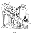
- Figures 1 to 4 are schematic illustrations of a preferred example of embodiment of a device for the production of plastic objects moulded by means of compression moulding according to the invention, which comprises a filling station, designated globally by numeral 1, and a compression station, designated globally by 4.
- the filling station 1 is a purposely designed device capable of dropping a pre-set dose of plastic material to be moulded into the moulding cavity 2 of a negative half-mould 3.
- the filling device 1 of Figures 1 and 2 comprises a rotating carousel (or filling carousel), which, rotating about a vertical axis A-A, in an area 5, continuously picks up dosed amounts of extruded plastic material from a plastication screw 6, for instance, within variable-volume dosing chambers 7, which are arranged in the proximity of the outer edge of the filling carousel, and carries them into a discharge area 8, where it drops them into the moulding cavity 2 ( Figure 3) of a negative or female half-mould 3, causing them to come out through an opening (not shown) of each dosing chamber 7.
- the openings of the various variable-volume dosing chambers 7 move along a circular path C'.
- the compression station 4 comprises a second rotating carousel, also referred to as compression carousel, which can rotate about a second vertical axis B-B different from the axis A-A and on which there are mounted a number of moulding units 9, each of which comprises one or more elements defined core moulds or male or positive-mould elements, (not shown) and the corresponding negative half-moulds 3 (see Figures 3 and 4), the former being mounted on top of the latter.
- a second rotating carousel also referred to as compression carousel
- moulding units 9 each of which comprises one or more elements defined core moulds or male or positive-mould elements, (not shown) and the corresponding negative half-moulds 3 (see Figures 3 and 4), the former being mounted on top of the latter.
- Each moulding unit is designed to carry out moulding cycles which comprise an operation of opening the mould, an operation of filling the moulding cavity 2 with a small mass of fluid plastic material, and an operation of closing and cooling the mould.
- Appropriate fixing and moving means enable opening and closing of each moulding unit by lowering and raising each positive-mould element or half-mould (not illustrated in the Figures) on the corresponding negative half-mould with a vertical rectilinear travel or stroke.
- one or more moulding units 9 are filled by the filling carousel, which drops a dose of fluid plastic material, in the form of a rounded mass or small ball, into the corresponding moulding cavities.
- the plastic material is cooled with the mould closed, whilst yet other moulding units 9 are opened for extraction of the plastic objects, which are by now in a sufficiently solidified state, for discharge thereof from the moulding station 4, and for sending them on to processing stations set downstream.
- the objects to be moulded are parisons made of polyethylene terephthalate (PET), which are to be used for the production, by blow moulding, of bottles for foodstuffs, jam jars, or other types of containers.
- PET polyethylene terephthalate
- the fixing and moving means are designed to bring the moulding cavity 2 of each negative half-mould, after the operation of opening of the mould and before the operation of filling a moulding cavity within a moulding cycle, into a position outside of the vertical axes of the positive-mould element, where by the expression "position outside of the vertical axes of the positive-mould element" is meant a position in which the vertical of no point of the positive-mould element or core mould falls on the moulding cavity.
- each negative half-mould 3 comprise a cam-actuating mechanism 13, an example of which is represented in Figures 3 and 4.
- Each negative half-mould 3 is mounted on a slide 10, which is designed to slide horizontally in a radial direction with respect to the moulding carousel 4 and the axis of rotation B-B.
- the slide 10 is constantly pushed towards the outside of the carousel by a compression spring 11 guided by the sliding rod 12.
- Figure 3 shows the slide 10 in two different positions, P1 and P2.
- the negative half-mould 3 In position P1 (where the slide 10 is closer to the axis B-B) the negative half-mould 3 is positioned underneath the male element in a position such as to enable lowering of the latter and closing of the mould, whereas in position P2 (where the slide 10 is further away from the axis B-B), the negative half-mould is underneath the filling and dosing station 1 in a position such that it is able to receive a dose of fluid plastic material dropped from the station 1 itself.
- Figure 4 is a three-dimensional view of the cam device 13.
- the flexible hoses 14 enable the half-moulds to be kept connected to the cooling circuit during the entire moulding cycle.
- Figure 2 is a schematic top-plan view of the path of the negative half-moulds along the cam.
- Appropriate mechanical grips block the slide with respect to the compression carousel 4 at a fixed distance from the axis of rotation B and thus keep it immobilised throughout the steps of compression, cooling, re-opening of the mould, and extraction of the parison. During these steps, each mould consequently moves along the circular path C.
- each compression spring 1.1 carries the wheel 15 into a position where it bears upon the profile of the cam 16 and, whilst the compression carousel proceeds in its rotation about the axis B, each negative half-mould 3 is deviated by the circular path C and is pushed outside said path by the cam-actuating mechanism 13, so as to position itself underneath the filling station 1 for being filled.
- the path of the cam 13 is such as to keep each moulding cavity 2 to be filled and the aperture of the variable-volume chamber 7 vertically aligned along a sufficiently long stretch T of the path C' defined by the movement of the dosing chambers 7.
- T of the path C' defined by the movement of the dosing chambers 7.
- the path of the cam 13 will clearly take into account the effects of the centrifugal forces that have upon the paths of the doses of plastic material as it is dropped, and also the path C' of the dosing chambers may be not only circular but also assume other forms so as to facilitate depositing of the doses in the moulding cavities by dropping.
- the negative half-moulds 3 that have been filled are made to pass again beneath the respective positive half-moulds by the profile of the cam 16 and are then clamped by the mechanical- grips in a fixed position on the compression carousel, resuming their progress along the circular path C.
- Each moulding unit 9 hence performs a new sequence of closing of the mould, cooling of the plastic material, opening of the mould, and extraction of the solidified moulded piece, followed by expulsion of the piece in the direction of the processing stations set downstream of the station described here.
- the parisons can, for example, be loaded onto a continuous chain conveyor or equivalent piece of equipment, which sends them on to a blowing machine, which is advantageously a continuous-cycle machine, or else to a generic processing station set downstream in the production process.
- the parisons are unloaded from the compression stations illustrated in Figures 1 and 2 at an appropriate temperature, and their cooling is completed in a cooling station set downstream, which can be made at lower costs than the compression station.
- the compression station can operate at higher production rates or, in other words, an ensemble made up of a compression station and a cooling station can be provided at initial costs that are lower than the costs for a single compression station having an equal output rate.
- each negative half-mould 3 outwards enables use of filling and dosing stations even of large dimensions both as regards their height and, in the case of rotating-carousel filling stations 1, as regards the diameter of the carousel itself.
- This fact also enables an increase in the production rate of the dosing station, as well as enabling installation on the dosing station of the devices necessary for dispensing plastic materials that are difficult to handle, such as, for example, PET -which tends to form strings by sticking to the walls with which it comes into contact -, as well as filling with considerable doses of plastic, etc.
- the moulds of the various moulding units have just one moulding cavity 2, and each moulding unit actuates and moves a single mould independently of the other half-moulds.
- This enables a uniform rotation of the compression carousel and reduces mechanical sizing of the cam device 13, since the various negative half-moulds are small and light.
- the example of embodiment described above may undergo various modifications. Clearly, it may be applied to the moulding of objects that are not necessarily parisons for blow moulding of bottles made of plastic materials.
- the filling station 1 may be a sequentially operating one, instead of a continuously operating one.
- the negative half-moulds 3 may have more than one moulding cavity 2.
- the half-moulds in the compression stations 9 may be moved not only by turntables along circular paths but, more generally, on systems for moving of various types, such as, for example, lines for movement on pallets and along closed paths of varying geometrical shape.
- the moulds may be opened and closed with strokes that are other than vertical, and the moulding cavities 2 can be displaced outside the vertical axes of the positive half-mould with a movement that is not only orthogonal but, more in general, transverse to the opening and closing strokes of the moulds.
- the process described above may be applied to the moulding not only of objects made of PET, but also of objects made of other plastic materials, amongst which, for example, PS, PE, PP, PVC, PEN and PBT.
Landscapes
- Engineering & Computer Science (AREA)
- Mechanical Engineering (AREA)
- Robotics (AREA)
- Casting Or Compression Moulding Of Plastics Or The Like (AREA)
- Moulds For Moulding Plastics Or The Like (AREA)
- Processing And Handling Of Plastics And Other Materials For Molding In General (AREA)
- Blow-Moulding Or Thermoforming Of Plastics Or The Like (AREA)
- Auxiliary Devices For And Details Of Packaging Control (AREA)
Claims (10)
- Vorrichtung zum Pressformen von Kunststoffobjekten, umfassend- eine Vielzahl von Pressform-Einheiten (9), die um eine Achse (B-B) auf einem sich drehenden Karussell (4), welches in der Lage ist, sich um die Achse (B-B) entlang eines ersten Pfads (C) zu drehen, befestigt sind, wobei jede der Form-Einheiten (9) ein positives Formelement sowie eine negative Halbform (3) umfasst, welche einen Form-Hohlraum (2) umfasst, der in der Lage ist, durch das Fallen lassen einer Kunststoffmaterial-Dosis aus einer Befüllvorrichtung (1) befüllt zu werden, wobei die Vorrichtung zum Pressen des Weiteren Mittel zum Ausführen von Formgebungs-Sequenzen umfasst, die einen Betrieb der Öffnung der Formeinheiten sowie einem Betrieb der Befüllung des Form-Hohlraums (2) und einen Betrieb der Absenkung des positiven Formelements und des Verschließens der Form-Einheiten umfassen,- Elemente zum Fixieren und Bewegen des positiven Formelements und/oder der negativen Halbform (3),dadurch gekennzeichnet, dass
zwischen dem Betrieb der Öffnung der Formeinheiten und dem Betrieb der Befüllung des Form-Hohlraums das Element zur Fixierung und Bewegung in der Lage ist, jede der negativen Halbformen (3) zur Ausrichtung des Hohlraums (2) unterhalb der Befüllungsvorrichtung (1) aus dem ersten Pfad (C) heraus zu verschieben. - Vorrichtung gemäß Anspruch 1, wobei das Element zum Fixieren und Bewegen in der Lage ist, jede der Form-Hohlräume (2) aus der vertikalen Achse des positiven Formelements heraus zu bringen, jeden Form-Hohlraum in Bezug auf das positive Formelement in einer Richtung quer zum Öffnungs- oder Verschließ-Hub der Form zu verschieben.
- Vorrichtung gemäß Anspruch 2, wobei das Element zum Fixieren und Bewegen in der Lage ist, den Form-Hohlraum (2) aus den vertikalen Achsen des positiven Formelements heraus zu bringen und den Form-Hohlraum aus dem Dreh-Karussell (4) heraus zu verschieben.
- Vorrichtung gemäß einem der voranstehenden Ansprüche, wobei das Element zum Fixieren und Bewegen eines Nockenbetätigungsmechanismus (13) zum Betätigen der negativen Halbform (3) umfasst.
- Vorrichtung gemäß Anspruch 4, wobei jedes Element zum Fixieren und Bewegen in der Lage ist, jeden Form-Hohlraum (2) aus den vertikalen Achsen des positiven Formelements durch eine Bewegung heraus zu bringen, die von den anderen Form-Hohlräumen (2) unabhängig ist.
- Vorrichtung gemäß Anspruch 5, wobei sie eine Dosiervorrichtung (1) umfasst, die zumindest eine Öffnung beinhaltet, aus der individuelle Dosen von Kunststoffmaterial fallen gelassen werden und die so gestaltet ist, dass sie sich entlang eines zweiten Pfads (C') bewegt, und dass der Nockenbetätigungsmechanismus (13) in der Lage ist, den zu befüllenden Form-Hohlraum (2) und die Öffnung übereinander einer Strecke (T) folgend einzustellen.
- Verfahren zur Herstellung von Kunststoffobjekten durch Pressformen unter Verwendung einer Vorrichtung, umfassend- eine Vielzahl von Pressform-Einheiten (9), die um eine Achse (B-B) auf einem sich drehenden Karussell (4) befestigt sind, welches in der Lage ist, sich um die Achse (B-B) entlang eines ersten Pfads (C) zu drehen, wobei jede der Form-Einheiten (9) ein positives Formelement sowie eine negative Halbform (3), die einen Form-Hohlraum (2) umfasst, umfasst,- sowie Elemente zum Fixieren und Bewegen des positiven Formelements und/oder der negativen Halbform (3),wobei das Verfahren die folgenden Schritte umfasst:a) Öffnen jeder Formeinheit (9) durch Entfernen der negativen Halbform (3) und des positiven Formelements mittels einer vertikalen Verschiebung;b) Befüllen jedes Form-Hohlraums (2) jeder negativen Halbform (3) durch Fallen lassen einer Dosis von zu formendem Kunststoffmaterial aus einer Befüllungsvorrichtung (1);c) Absenken des positiven Formelements auf die negative Halbform (3), wodurch die negative Halbform (3) zurück unter das korrespondierende positive Formelement gebracht wird, und;d) Verschließen des positiven Formelements und der negativen Halbform (3) miteinander;dadurch gekennzeichnet, dass
zwischen den Schritten a) und b) ein Schritt des Verbringens des Form-Hohlraums (2) jeder negativen Halbform (3) in eine Position außerhalb des ersten Pfads (C) zum Ausrichten des Hohlraums (2) unterhalb der Befüllungsvorrichtung (1). - Verfahren gemäß Anspruch 7, wobei der Form-Hohlraum (2) von einer ersten Formeinheit (9) befüllt wird, während zumindest in einer zweiten Formeinheit eine Abkühlung des Kunststoffmaterials eintritt und/oder zumindest eine dritte Formeinheit zur Extraktion des geformten Objekts geöffnet wird.
- Verfahren gemäß Anspruch 7, wobei das die geformten Objekte ausbildende Material zumindest eins der folgenden Materialien umfasst: PET, PS, PE, PP, PVC, PEN, PBT.
- Verfahren gemäß Anspruch 7, wobei die geformten Objekte Extrudate für die Herstellung von hohlen Objekten oder Behältern mittels Blasumformung sind.
Applications Claiming Priority (3)
| Application Number | Priority Date | Filing Date | Title |
|---|---|---|---|
| ITRM20010723 | 2001-12-07 | ||
| IT2001RM000723A ITRM20010723A1 (it) | 2001-12-07 | 2001-12-07 | Dispositivo e metodo di stampaggio per compressione di articoli in plastica. |
| PCT/EP2002/013763 WO2003047834A1 (en) | 2001-12-07 | 2002-12-05 | Device and method for compression moulding of plastic articles |
Publications (2)
| Publication Number | Publication Date |
|---|---|
| EP1458539A1 EP1458539A1 (de) | 2004-09-22 |
| EP1458539B1 true EP1458539B1 (de) | 2007-07-04 |
Family
ID=11455912
Family Applications (1)
| Application Number | Title | Priority Date | Filing Date |
|---|---|---|---|
| EP02790472A Expired - Lifetime EP1458539B1 (de) | 2001-12-07 | 2002-12-05 | Vorrichtung und verfahren zum pressformen von kunststoff-artikeln |
Country Status (13)
| Country | Link |
|---|---|
| US (1) | US7425124B2 (de) |
| EP (1) | EP1458539B1 (de) |
| JP (1) | JP2005511347A (de) |
| CN (1) | CN100354100C (de) |
| AT (1) | ATE366170T1 (de) |
| AU (1) | AU2002365636A1 (de) |
| BR (1) | BR0214660B1 (de) |
| CA (1) | CA2469248C (de) |
| DE (1) | DE60221043T2 (de) |
| ES (1) | ES2289170T3 (de) |
| IT (1) | ITRM20010723A1 (de) |
| RU (1) | RU2298472C2 (de) |
| WO (1) | WO2003047834A1 (de) |
Families Citing this family (29)
| Publication number | Priority date | Publication date | Assignee | Title |
|---|---|---|---|---|
| AU2004257059A1 (en) * | 2003-07-14 | 2005-01-27 | Toyo Seikan Kaisha, Ltd. | Method and device for forcibly inserting drop into compression molding machine, and molding die follow-up type method and device for supplying drop |
| ITRE20040009A1 (it) * | 2004-02-04 | 2004-05-04 | Sacmi | Impianto per la formatura a compressione di oggetti di plastica |
| US7178562B2 (en) * | 2004-04-08 | 2007-02-20 | Graham Packaging Pet Technologies Inc. | Pellet transfer apparatus and method |
| EP1755848A2 (de) * | 2004-04-23 | 2007-02-28 | Sacmi Cooperativa Meccanici Imola Societa' Cooperativa | Vorrichtung und verfahren zur übertragung von kunststoffmaterial zu einer formpressmaschine |
| JP4703642B2 (ja) * | 2004-04-23 | 2011-06-15 | サックミ コーペラティバ マッカニキ イモラ ソシエタ コーペラティバ | 装置及び方法 |
| US7632089B2 (en) * | 2004-05-07 | 2009-12-15 | Graham Packaging Pet Technologies, Inc. | Take out and cooling system and method |
| ITMO20050048A1 (it) * | 2005-03-01 | 2006-09-02 | Sacmi | Apparati e metodi. |
| ITRE20050015A1 (it) * | 2005-03-01 | 2006-09-02 | Sacmi | Gruppo e metodo per la formatura a compressione di oggetti in materiale polimerico entro stampi |
| US7481646B2 (en) * | 2005-06-17 | 2009-01-27 | Rexam Closure Systems Inc. | Compression molding machine |
| US7407376B2 (en) | 2005-07-21 | 2008-08-05 | Graham Packaging Company, L.P. | Compression molding apparatus |
| EP2404732B1 (de) * | 2006-02-17 | 2017-05-17 | Toyo Seikan Group Holdings, Ltd. | Verfahren und Vorrichtung zum Zuführen einer geschmolzenen Kunststoffmasse in einer Pressform |
| JP2007216531A (ja) * | 2006-02-17 | 2007-08-30 | Toyo Seikan Kaisha Ltd | 圧縮成形システム |
| US7628601B2 (en) * | 2007-07-30 | 2009-12-08 | Rexam Closure Systems Inc. | Machine for compression molding plastic articles |
| JP5098535B2 (ja) * | 2007-09-21 | 2012-12-12 | 東洋製罐株式会社 | 溶融樹脂供給装置 |
| US7621735B2 (en) * | 2007-10-18 | 2009-11-24 | Rexam Closure Systems Inc. | Apparatus for placing mold charges into a compression molding machine |
| ITMO20080023A1 (it) * | 2008-01-29 | 2009-07-30 | Sacmi | Apparato per trasferire dosi di materia plastica |
| JP4670883B2 (ja) * | 2008-03-19 | 2011-04-13 | 東洋製罐株式会社 | 溶融樹脂供給装置、溶融樹脂圧縮成形方法、溶融樹脂圧縮成形装置、及び合成樹脂製容器の製造方法 |
| US8356991B2 (en) * | 2009-03-12 | 2013-01-22 | Graham Engineering Corporation | Rotary blow molding machine with movable clamp assemblies and method |
| JP5739438B2 (ja) * | 2009-10-23 | 2015-06-24 | フレクストロニクス エイピー エルエルシーFlextronics Ap,Llc | 高速かつ低圧縮の熱可塑性材料の回転式成形装置及び成型方法 |
| BE1020382A5 (nl) * | 2012-04-30 | 2013-08-06 | Plastigi | Inrichting en werkwijze voor rotatiegieten van kunststof. |
| DE102012112491A1 (de) | 2012-12-18 | 2014-06-18 | Krones Ag | Vorrichtung und Verfahren zum Herstellen von Kunststoffvorformlingen aus einem thermoplastischen Kunststoff |
| EP2821197A1 (de) * | 2013-07-03 | 2015-01-07 | Aisapack Holding SA | Indexierende Schweißvorrichtung für Rohr |
| ITRM20130490A1 (it) * | 2013-09-04 | 2015-03-05 | Sipa Progettazione Automaz | Pinze di presa per contenitori di termoplastica |
| CN104191582B (zh) * | 2014-09-10 | 2016-05-04 | 张家港市亿利机械有限公司 | 一种塑料板材成型机 |
| MX354864B (es) * | 2014-09-30 | 2018-03-23 | Kimberly Clark Co | Aparato y método de compresión. |
| KR101796727B1 (ko) * | 2014-09-30 | 2017-11-10 | 킴벌리-클라크 월드와이드, 인크. | 압축 장치 및 방법 |
| ITUB20154653A1 (it) * | 2015-10-14 | 2017-04-14 | Sacmi | Apparato e metodo per processare dosi. |
| IT202100032507A1 (it) * | 2021-12-23 | 2023-06-23 | Sacmi | Apparato e metodo per produrre in ciclo continuo contenitori realizzati in materiale plastico. |
| US12564989B2 (en) * | 2024-04-25 | 2026-03-03 | Kuka Systems North America Llc | Transfer molding system and methods |
Family Cites Families (20)
| Publication number | Priority date | Publication date | Assignee | Title |
|---|---|---|---|---|
| US1601836A (en) * | 1923-11-23 | 1926-10-05 | Hazel Atlas Glass Co | Forming machine |
| US1845525A (en) * | 1928-05-24 | 1932-02-16 | Macbeth Evans Glass Co | Glass forming machine |
| US2383349A (en) * | 1940-05-27 | 1945-08-21 | Edwin E Slick | Glassware working apparatus |
| GB703689A (en) * | 1949-07-25 | 1954-02-10 | A C I Plastics Proprietary Ltd | Improved apparatus for moulding plastic materials |
| US2891281A (en) * | 1954-03-19 | 1959-06-23 | Armstrong Cork Co | Rotary molding device |
| NL126305C (de) * | 1962-07-19 | 1900-01-01 | ||
| US3375553A (en) * | 1966-03-11 | 1968-04-02 | Owens Illinois Inc | Valve device for plastic extruder |
| US3849041A (en) * | 1973-04-30 | 1974-11-19 | Minnesota Mining & Mfg | Apparatus for manufacturing environmental seed cells |
| JPS6045045B2 (ja) * | 1977-12-27 | 1985-10-07 | 株式会社吉野工業所 | 延伸ブロ−成形装置 |
| CN1003434B (zh) * | 1985-07-20 | 1989-03-01 | 东洋制罐株式会社 | 压塑设备 |
| US5088915A (en) * | 1988-06-08 | 1992-02-18 | Korsch Ohg Maschinenfabrik | Coated-core press |
| RU2021129C1 (ru) * | 1990-03-26 | 1994-10-15 | Аиса Отомасьон Эндюстриель С.А. | Устройство для изготовления тюбиков |
| DE4009661C1 (de) | 1990-03-26 | 1991-03-07 | Aisa Automation Industrielle S.A., Vouvry, Ch | |
| US6074583A (en) * | 1993-10-14 | 2000-06-13 | Owens-Illinois Closure Inc. | Method and apparatus for compression molding plastic articles |
| DE4417435C1 (de) * | 1994-05-18 | 1996-01-04 | Automation Industrielle Sa | Verfahren und Vorrichtungen zur Herstellung eines Formkörpers aus Kunststoff |
| ITBO940242A1 (it) | 1994-05-23 | 1995-11-23 | Sacmi | Apparecchiatura per lo stampaggio a pressione di articoli in materiale plastico, come capsule per la chiusura di contenitori e simili. |
| US5672364A (en) * | 1994-07-07 | 1997-09-30 | Sankyo Seisakusho Co. & Eisai Co., Ltd. | Apparatus for manufacturing tablets |
| US5603964A (en) * | 1994-10-07 | 1997-02-18 | Owens-Illinois Closure Inc. | Apparatus for cutting and delivering plastic gobs |
| DE19654350A1 (de) * | 1996-12-24 | 1998-06-25 | Krupp Corpoplast Masch | Verfahren und Vorrichtung zur Übergabe von Formlingen |
| US5866177A (en) | 1997-05-16 | 1999-02-02 | Owens-Illinois Closure Inc. | Apparatus for compression molding plastic articles |
-
2001
- 2001-12-07 IT IT2001RM000723A patent/ITRM20010723A1/it unknown
-
2002
- 2002-12-05 CN CNB028244001A patent/CN100354100C/zh not_active Expired - Fee Related
- 2002-12-05 CA CA2469248A patent/CA2469248C/en not_active Expired - Fee Related
- 2002-12-05 JP JP2003549064A patent/JP2005511347A/ja active Pending
- 2002-12-05 RU RU2004120707/12A patent/RU2298472C2/ru not_active IP Right Cessation
- 2002-12-05 AU AU2002365636A patent/AU2002365636A1/en not_active Abandoned
- 2002-12-05 ES ES02790472T patent/ES2289170T3/es not_active Expired - Lifetime
- 2002-12-05 BR BRPI0214660-6A patent/BR0214660B1/pt not_active IP Right Cessation
- 2002-12-05 DE DE60221043T patent/DE60221043T2/de not_active Expired - Lifetime
- 2002-12-05 WO PCT/EP2002/013763 patent/WO2003047834A1/en not_active Ceased
- 2002-12-05 EP EP02790472A patent/EP1458539B1/de not_active Expired - Lifetime
- 2002-12-05 AT AT02790472T patent/ATE366170T1/de not_active IP Right Cessation
- 2002-12-05 US US10/497,843 patent/US7425124B2/en not_active Expired - Fee Related
Also Published As
| Publication number | Publication date |
|---|---|
| WO2003047834A1 (en) | 2003-06-12 |
| CA2469248A1 (en) | 2003-06-12 |
| US20050031723A1 (en) | 2005-02-10 |
| RU2004120707A (ru) | 2005-03-10 |
| ES2289170T3 (es) | 2008-02-01 |
| CA2469248C (en) | 2010-09-21 |
| DE60221043T2 (de) | 2008-03-06 |
| RU2298472C2 (ru) | 2007-05-10 |
| JP2005511347A (ja) | 2005-04-28 |
| BR0214660B1 (pt) | 2011-11-29 |
| EP1458539A1 (de) | 2004-09-22 |
| CN100354100C (zh) | 2007-12-12 |
| US7425124B2 (en) | 2008-09-16 |
| AU2002365636A1 (en) | 2003-06-17 |
| BR0214660A (pt) | 2004-11-03 |
| ITRM20010723A1 (it) | 2003-06-09 |
| CN1599661A (zh) | 2005-03-23 |
| ATE366170T1 (de) | 2007-07-15 |
| DE60221043D1 (de) | 2007-08-16 |
Similar Documents
| Publication | Publication Date | Title |
|---|---|---|
| US7425124B2 (en) | Device and method for compression moulding of plastic articles | |
| EP0070189A1 (de) | Spritzstreckblasgiessmaschine | |
| EP2017202A1 (de) | Verfahren zum Bewegen von Gegenständen | |
| US9796119B2 (en) | Injection mold of a plastic preform | |
| JP3130140B2 (ja) | 射出延伸吹込成形方法及び装置 | |
| CN217293468U (zh) | 直线式注吹一体的塑料瓶成型设备 | |
| US9469062B2 (en) | Rotary joint for transferring melted plastic | |
| EP2361745A2 (de) | Kontinuierliche Formungsmaschine | |
| CN101827698B (zh) | 用于拉伸吹塑的装置和用于制造半成品的方法 | |
| EP1868787B1 (de) | Vorrichtung zur übertragung von dosen | |
| WO2003047831A1 (en) | Device and method for filling moulds | |
| TW202327852A (zh) | 用於從塑膠材料連續循環生產容器的設備和方法 | |
| EP1907186B1 (de) | Formpressgerät | |
| EP2554355B1 (de) | Vorrichtung und Verfahren zur Herstellung von Behältern | |
| JP2003534958A (ja) | プラスチック製プリフォーム用処理および冷却装置および方法 | |
| US20250001669A1 (en) | Resin container manufacturing device and resin container manufacturing method | |
| US4064210A (en) | Method for feeding and discharging blow molds | |
| CN107000262A (zh) | 用于在预制件上制造优化的颈部轮廓的方法和装置 | |
| EP4375045A1 (de) | Harzbehälterherstellungsvorrichtung und verfahren zur herstellung eines harzbehälters |
Legal Events
| Date | Code | Title | Description |
|---|---|---|---|
| PUAI | Public reference made under article 153(3) epc to a published international application that has entered the european phase |
Free format text: ORIGINAL CODE: 0009012 |
|
| 17P | Request for examination filed |
Effective date: 20040702 |
|
| AK | Designated contracting states |
Kind code of ref document: A1 Designated state(s): AT BE BG CH CY CZ DE DK EE ES FI FR GB GR IE IT LI LU MC NL PT SE SI SK TR |
|
| AX | Request for extension of the european patent |
Extension state: AL LT LV MK RO |
|
| RIC1 | Information provided on ipc code assigned before grant |
Ipc: B29C 43/34 20060101ALI20060616BHEP Ipc: B29C 31/06 20060101ALI20060616BHEP Ipc: B29C 43/08 20060101AFI20060616BHEP Ipc: B29C 33/36 20060101ALN20060616BHEP |
|
| GRAP | Despatch of communication of intention to grant a patent |
Free format text: ORIGINAL CODE: EPIDOSNIGR1 |
|
| GRAS | Grant fee paid |
Free format text: ORIGINAL CODE: EPIDOSNIGR3 |
|
| GRAA | (expected) grant |
Free format text: ORIGINAL CODE: 0009210 |
|
| AK | Designated contracting states |
Kind code of ref document: B1 Designated state(s): AT BE BG CH CY CZ DE DK EE ES FI FR GB GR IE IT LI LU MC NL PT SE SI SK TR |
|
| REG | Reference to a national code |
Ref country code: GB Ref legal event code: FG4D |
|
| REG | Reference to a national code |
Ref country code: CH Ref legal event code: EP |
|
| REG | Reference to a national code |
Ref country code: IE Ref legal event code: FG4D |
|
| REF | Corresponds to: |
Ref document number: 60221043 Country of ref document: DE Date of ref document: 20070816 Kind code of ref document: P |
|
| ET | Fr: translation filed | ||
| NLV1 | Nl: lapsed or annulled due to failure to fulfill the requirements of art. 29p and 29m of the patents act | ||
| REG | Reference to a national code |
Ref country code: CH Ref legal event code: PL |
|
| PG25 | Lapsed in a contracting state [announced via postgrant information from national office to epo] |
Ref country code: SI Free format text: LAPSE BECAUSE OF FAILURE TO SUBMIT A TRANSLATION OF THE DESCRIPTION OR TO PAY THE FEE WITHIN THE PRESCRIBED TIME-LIMIT Effective date: 20070704 Ref country code: FI Free format text: LAPSE BECAUSE OF FAILURE TO SUBMIT A TRANSLATION OF THE DESCRIPTION OR TO PAY THE FEE WITHIN THE PRESCRIBED TIME-LIMIT Effective date: 20070704 Ref country code: PT Free format text: LAPSE BECAUSE OF FAILURE TO SUBMIT A TRANSLATION OF THE DESCRIPTION OR TO PAY THE FEE WITHIN THE PRESCRIBED TIME-LIMIT Effective date: 20071204 Ref country code: BG Free format text: LAPSE BECAUSE OF FAILURE TO SUBMIT A TRANSLATION OF THE DESCRIPTION OR TO PAY THE FEE WITHIN THE PRESCRIBED TIME-LIMIT Effective date: 20071004 Ref country code: NL Free format text: LAPSE BECAUSE OF FAILURE TO SUBMIT A TRANSLATION OF THE DESCRIPTION OR TO PAY THE FEE WITHIN THE PRESCRIBED TIME-LIMIT Effective date: 20070704 |
|
| REG | Reference to a national code |
Ref country code: ES Ref legal event code: FG2A Ref document number: 2289170 Country of ref document: ES Kind code of ref document: T3 |
|
| PG25 | Lapsed in a contracting state [announced via postgrant information from national office to epo] |
Ref country code: AT Free format text: LAPSE BECAUSE OF FAILURE TO SUBMIT A TRANSLATION OF THE DESCRIPTION OR TO PAY THE FEE WITHIN THE PRESCRIBED TIME-LIMIT Effective date: 20070704 Ref country code: LI Free format text: LAPSE BECAUSE OF FAILURE TO SUBMIT A TRANSLATION OF THE DESCRIPTION OR TO PAY THE FEE WITHIN THE PRESCRIBED TIME-LIMIT Effective date: 20070704 Ref country code: CH Free format text: LAPSE BECAUSE OF FAILURE TO SUBMIT A TRANSLATION OF THE DESCRIPTION OR TO PAY THE FEE WITHIN THE PRESCRIBED TIME-LIMIT Effective date: 20070704 |
|
| PG25 | Lapsed in a contracting state [announced via postgrant information from national office to epo] |
Ref country code: BE Free format text: LAPSE BECAUSE OF FAILURE TO SUBMIT A TRANSLATION OF THE DESCRIPTION OR TO PAY THE FEE WITHIN THE PRESCRIBED TIME-LIMIT Effective date: 20070704 |
|
| PG25 | Lapsed in a contracting state [announced via postgrant information from national office to epo] |
Ref country code: GR Free format text: LAPSE BECAUSE OF FAILURE TO SUBMIT A TRANSLATION OF THE DESCRIPTION OR TO PAY THE FEE WITHIN THE PRESCRIBED TIME-LIMIT Effective date: 20071005 Ref country code: DK Free format text: LAPSE BECAUSE OF FAILURE TO SUBMIT A TRANSLATION OF THE DESCRIPTION OR TO PAY THE FEE WITHIN THE PRESCRIBED TIME-LIMIT Effective date: 20070704 |
|
| PLBE | No opposition filed within time limit |
Free format text: ORIGINAL CODE: 0009261 |
|
| STAA | Information on the status of an ep patent application or granted ep patent |
Free format text: STATUS: NO OPPOSITION FILED WITHIN TIME LIMIT |
|
| PG25 | Lapsed in a contracting state [announced via postgrant information from national office to epo] |
Ref country code: SK Free format text: LAPSE BECAUSE OF FAILURE TO SUBMIT A TRANSLATION OF THE DESCRIPTION OR TO PAY THE FEE WITHIN THE PRESCRIBED TIME-LIMIT Effective date: 20070704 Ref country code: CZ Free format text: LAPSE BECAUSE OF FAILURE TO SUBMIT A TRANSLATION OF THE DESCRIPTION OR TO PAY THE FEE WITHIN THE PRESCRIBED TIME-LIMIT Effective date: 20070704 |
|
| 26N | No opposition filed |
Effective date: 20080407 |
|
| PG25 | Lapsed in a contracting state [announced via postgrant information from national office to epo] |
Ref country code: SE Free format text: LAPSE BECAUSE OF FAILURE TO SUBMIT A TRANSLATION OF THE DESCRIPTION OR TO PAY THE FEE WITHIN THE PRESCRIBED TIME-LIMIT Effective date: 20071004 |
|
| PG25 | Lapsed in a contracting state [announced via postgrant information from national office to epo] |
Ref country code: MC Free format text: LAPSE BECAUSE OF NON-PAYMENT OF DUE FEES Effective date: 20071231 |
|
| PG25 | Lapsed in a contracting state [announced via postgrant information from national office to epo] |
Ref country code: IE Free format text: LAPSE BECAUSE OF NON-PAYMENT OF DUE FEES Effective date: 20071205 |
|
| PG25 | Lapsed in a contracting state [announced via postgrant information from national office to epo] |
Ref country code: EE Free format text: LAPSE BECAUSE OF FAILURE TO SUBMIT A TRANSLATION OF THE DESCRIPTION OR TO PAY THE FEE WITHIN THE PRESCRIBED TIME-LIMIT Effective date: 20070704 |
|
| PG25 | Lapsed in a contracting state [announced via postgrant information from national office to epo] |
Ref country code: CY Free format text: LAPSE BECAUSE OF FAILURE TO SUBMIT A TRANSLATION OF THE DESCRIPTION OR TO PAY THE FEE WITHIN THE PRESCRIBED TIME-LIMIT Effective date: 20070704 |
|
| PG25 | Lapsed in a contracting state [announced via postgrant information from national office to epo] |
Ref country code: IT Free format text: LAPSE BECAUSE OF NON-PAYMENT OF DUE FEES Effective date: 20071205 |
|
| PG25 | Lapsed in a contracting state [announced via postgrant information from national office to epo] |
Ref country code: TR Free format text: LAPSE BECAUSE OF FAILURE TO SUBMIT A TRANSLATION OF THE DESCRIPTION OR TO PAY THE FEE WITHIN THE PRESCRIBED TIME-LIMIT Effective date: 20070704 |
|
| PGFP | Annual fee paid to national office [announced via postgrant information from national office to epo] |
Ref country code: GB Payment date: 20101115 Year of fee payment: 9 |
|
| PGFP | Annual fee paid to national office [announced via postgrant information from national office to epo] |
Ref country code: DE Payment date: 20101116 Year of fee payment: 9 |
|
| PGFP | Annual fee paid to national office [announced via postgrant information from national office to epo] |
Ref country code: IT Payment date: 20101104 Year of fee payment: 9 |
|
| PGRI | Patent reinstated in contracting state [announced from national office to epo] |
Ref country code: IT Effective date: 20110616 |
|
| PGFP | Annual fee paid to national office [announced via postgrant information from national office to epo] |
Ref country code: ES Payment date: 20111116 Year of fee payment: 10 Ref country code: LU Payment date: 20111115 Year of fee payment: 10 Ref country code: FR Payment date: 20111129 Year of fee payment: 10 |
|
| GBPC | Gb: european patent ceased through non-payment of renewal fee |
Effective date: 20121205 |
|
| REG | Reference to a national code |
Ref country code: FR Ref legal event code: ST Effective date: 20130830 |
|
| PG25 | Lapsed in a contracting state [announced via postgrant information from national office to epo] |
Ref country code: DE Free format text: LAPSE BECAUSE OF NON-PAYMENT OF DUE FEES Effective date: 20130702 |
|
| REG | Reference to a national code |
Ref country code: DE Ref legal event code: R119 Ref document number: 60221043 Country of ref document: DE Effective date: 20130702 |
|
| PG25 | Lapsed in a contracting state [announced via postgrant information from national office to epo] |
Ref country code: GB Free format text: LAPSE BECAUSE OF NON-PAYMENT OF DUE FEES Effective date: 20121205 Ref country code: FR Free format text: LAPSE BECAUSE OF NON-PAYMENT OF DUE FEES Effective date: 20130102 |
|
| PG25 | Lapsed in a contracting state [announced via postgrant information from national office to epo] |
Ref country code: IT Free format text: LAPSE BECAUSE OF NON-PAYMENT OF DUE FEES Effective date: 20121205 |
|
| REG | Reference to a national code |
Ref country code: ES Ref legal event code: FD2A Effective date: 20140306 |
|
| PG25 | Lapsed in a contracting state [announced via postgrant information from national office to epo] |
Ref country code: ES Free format text: LAPSE BECAUSE OF NON-PAYMENT OF DUE FEES Effective date: 20121206 Ref country code: LU Free format text: LAPSE BECAUSE OF NON-PAYMENT OF DUE FEES Effective date: 20121205 |