EP1459623B1 - Dispositif de séparation des stalles - Google Patents
Dispositif de séparation des stalles Download PDFInfo
- Publication number
- EP1459623B1 EP1459623B1 EP04004760A EP04004760A EP1459623B1 EP 1459623 B1 EP1459623 B1 EP 1459623B1 EP 04004760 A EP04004760 A EP 04004760A EP 04004760 A EP04004760 A EP 04004760A EP 1459623 B1 EP1459623 B1 EP 1459623B1
- Authority
- EP
- European Patent Office
- Prior art keywords
- tube
- aforementioned
- partitioning
- supporting
- bent
- Prior art date
- Legal status (The legal status is an assumption and is not a legal conclusion. Google has not performed a legal analysis and makes no representation as to the accuracy of the status listed.)
- Expired - Lifetime
Links
- 238000000926 separation method Methods 0.000 title abstract description 36
- 241001465754 Metazoa Species 0.000 claims abstract description 28
- 238000005452 bending Methods 0.000 claims description 7
- 241000283690 Bos taurus Species 0.000 claims description 6
- 230000002441 reversible effect Effects 0.000 claims description 6
- 238000004873 anchoring Methods 0.000 claims description 2
- 238000000638 solvent extraction Methods 0.000 claims 10
- 241000282898 Sus scrofa Species 0.000 claims 2
- 244000144972 livestock Species 0.000 claims 1
- 230000000284 resting effect Effects 0.000 abstract 1
- 238000003466 welding Methods 0.000 abstract 1
- 240000008669 Hedera helix Species 0.000 description 12
- 208000027418 Wounds and injury Diseases 0.000 description 3
- 230000008901 benefit Effects 0.000 description 3
- 230000006378 damage Effects 0.000 description 3
- 208000014674 injury Diseases 0.000 description 3
- 230000000670 limiting effect Effects 0.000 description 3
- 238000004519 manufacturing process Methods 0.000 description 3
- 230000002829 reductive effect Effects 0.000 description 3
- 230000007704 transition Effects 0.000 description 3
- 229910000831 Steel Inorganic materials 0.000 description 2
- 239000010959 steel Substances 0.000 description 2
- 239000004677 Nylon Substances 0.000 description 1
- 229910001294 Reinforcing steel Inorganic materials 0.000 description 1
- 241000282887 Suidae Species 0.000 description 1
- 230000006978 adaptation Effects 0.000 description 1
- 238000010276 construction Methods 0.000 description 1
- 238000011109 contamination Methods 0.000 description 1
- 230000008878 coupling Effects 0.000 description 1
- 238000010168 coupling process Methods 0.000 description 1
- 238000005859 coupling reaction Methods 0.000 description 1
- 230000001419 dependent effect Effects 0.000 description 1
- 210000005069 ears Anatomy 0.000 description 1
- 239000013013 elastic material Substances 0.000 description 1
- 238000005516 engineering process Methods 0.000 description 1
- 230000004886 head movement Effects 0.000 description 1
- 238000010409 ironing Methods 0.000 description 1
- 230000002147 killing effect Effects 0.000 description 1
- 239000000463 material Substances 0.000 description 1
- 239000002184 metal Substances 0.000 description 1
- 229920001778 nylon Polymers 0.000 description 1
- 238000005192 partition Methods 0.000 description 1
- 230000002787 reinforcement Effects 0.000 description 1
- 230000000717 retained effect Effects 0.000 description 1
- 238000007493 shaping process Methods 0.000 description 1
- 239000004575 stone Substances 0.000 description 1
- 239000000725 suspension Substances 0.000 description 1
- 239000002023 wood Substances 0.000 description 1
Images


Classifications
-
- A—HUMAN NECESSITIES
- A01—AGRICULTURE; FORESTRY; ANIMAL HUSBANDRY; HUNTING; TRAPPING; FISHING
- A01K—ANIMAL HUSBANDRY; AVICULTURE; APICULTURE; PISCICULTURE; FISHING; REARING OR BREEDING ANIMALS, NOT OTHERWISE PROVIDED FOR; NEW BREEDS OF ANIMALS
- A01K1/00—Housing animals; Equipment therefor
- A01K1/0005—Stable partitions
- A01K1/0011—Cubicle partitions
Definitions
- the invention relates to a separation device for stable boxes for keeping animals such as cows, cattle, pigs or the like with a separator tube and two support tubes for floor mounting, wherein the two support tubes are formed by the end portions and the separation tube through the intermediate tube portion of the integrally bent tube in that the separator tube has at least one reverse bend and is bent to form a divider or divider so that it has at least two spaced-apart spars located at different heights, with lateral offset for the support tubes being provided by corresponding flexing of the integral tube.
- a separation device for animal husbandry in Anbindetelln comprising a bent in a U-shaped separation frame, which is connected to a support device for a connecting the animal serving cross member, wherein the two legs of the U-shaped separation frame are used for anchoring the separation frame in the stable floor and the support device for the cross member is slidably mounted with its lower end to the frame portion connecting the two legs of the U-shaped separation frame to components create that are easy to produce, their assembly is easy to carry out and are easily detached from each other and therefore are easy to adapt to different tethering systems and to the local conditions.
- the object of the invention is to provide a separating device which is easier to manufacture and in which a risk of breakage is reduced.
- this object is achieved in that the ends of the same length support tubes are arranged side by side in the region of a bottom bracket.
- the separation device according to the invention is achieved by the features that the ends of the same length support tubes are arranged in the region of a bottom-side bracket side by side, that complex items and joints account for the known devices.
- the separating device according to the invention is therefore particularly easy to manufacture and very stable, so that a risk of breakage is reduced.
- the separating device according to the invention forms a way to provide by appropriate shaping during bending of the pipe a yielding shape for the separation, so that the benefits of a separating device according to the above-mentioned state of the Technology, ie a reduction in the risk of injury to the animals can be realized.
- Such a yielding shape can be achieved, for example, by bending a support tube extending from the bottom upwards in the lateral direction to form a separating tube or separating frame.
- a support tube extending from the bottom upwards in the lateral direction to form a separating tube or separating frame.
- an exploitation of the elasticity of a metal tube, such as a steel pipe is possible to achieve the desired flexibility of the separation without further expensive additional measures.
- the separating tube is hereby bent to form a separating frame, so that it comprises at least two spars spaced at different heights.
- a separation frame can be realized which fulfills the desired function in a conventional manner at different heights, so that a reliable separation is possible, without the risk that an animal above or below the separation tube overcomes the separation.
- the divider tube is preferably bent so as to have at least one reverse bend.
- the two spaced apart spars can be easily arranged as pipe sections at different heights.
- the separating tube can be bent to form an open separating bow or to a self-contained separating frame, wherein the separation tube merges into at least one support tube in at least one end region, which can be fastened on the bottom side.
- the one or more support tubes are able to carry the entire separator.
- two support tubes are provided, which increases the stability of the separating device.
- the two support tubes are preferably formed by both end portions and the separation tube through the intervening tube portion of the one-piece tube from which the separating device is bent.
- the separation is bent so that the separation tube or the separating bracket or separating frame formed therefrom and the one or more support tubes lie in one plane.
- both end portions of the integrally bent tube can be used as a support tube, which are arranged either directly adjacent to each other or with a certain distance become. The exact arrangement of these support tubes in this case influences the stability and flexibility of the separator.
- the two support tubes formed by end regions of the bent tube are arranged side by side relative to the longitudinal direction of the separating device.
- the tube is thus not completely bent in a plane, but has a certain transverse offset, so that the two end regions come to lie next to each other.
- This arrangement has a particularly good flexibility in the vertical direction, since in this arrangement a yielding or a bending of the support tubes without deformation of the intermediate separating tube or separating bracket or separating frame is possible.
- a separating device according to the invention can be used with suitable holding elements readily in wall mounting or with a bottom-side support in the floor mounting.
- the separating device is also suitable for housing facilities in which the stable box according to the invention is spaced from a wall and thus arranged without the possibility of wall mounting.
- the bottom-side bracket is preferably designed as a clamping or plug-in bracket which jams the or the end support tubes of the separating device or at least partially receives a positive fit.
- this is an or a plurality of clamping or plug-in sleeves provided, in which the end-side support tubes of the separating device can be inserted and optionally clamped or braced by means of corresponding clamping elements, such as screws or the like.
- the bottom-side attachment is made outside the lying area of the animal, so that the lying animal is not affected by this support.
- the pipe end (s) forming the support pipe (s) are bent so as to be substantially vertical in the assembled state.
- the attachment of such vertical tubes is possible with minimal extent of any bottom-side fasteners, so that the animals are not or only slightly affected by such fasteners in their freedom of movement.
- the tube end (s) forming one or two support tubes may also be bent in a substantially horizontal direction.
- a substantially horizontally expiring pipe end has the advantage that it is to clamp with simple ironing on the ground.
- a front boundary of the lying surface is preferably provided, which may be formed for example in the form of a bentwood.
- Such an anterior boundary ensures that the animal or animals are in put the provided area for lying and thus remain especially when getting up in this area.
- an additional neck limitation is preferably provided, which is intended to limit a forward stride of the animals.
- such neck limitation is designed to be flexible in order to reduce the risk of injury to the animals when getting up.
- a flexible neckline can for example be formed by an elastic band or an elastic rope, but there is also the possibility of a non-compliant in length, but flexible material such as a chain, a tensile rope or the like by corresponding resilient edge fasteners, for example against to make a spring or the like in the desired sense flexible.
- the individual separation devices can be connected by a stiffening and Abgrenzrohr and thus also stiffened, this stiffening and Abgrenzrohr is advantageously provided with a bulge to ensure a good neck and / or back freedom.
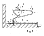
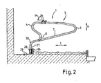
- FIGS. 1 and 2 each show a separation device 1 according to the invention, which is bent from a one-piece tube 2.
- the central region of the tube 2 is bent by two reverse bends 3, 4 to form a closed separating frame 5 with an upper spar 6 and a lower spar 7.
- the front reversal bend 4 merges into a counterbending 8, resulting in an advantageous headroom of the animal lying in the region 9 before this counterbending 8.
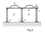
- the end portions of the tube 2 are to support tubes 10, 11 (see. FIG. 3 ) educated.
- the embodiment according to FIG. 1 and 3 go the support tubes 10, 11 via a vertical section 12 in a horizontal section 13, where they are attached to a mounting bracket 14 at the bottom with screw 15.
- a bentwood 16 is attached to the support tubes 10, 11 at the front of the cubicle 17 formed by the separating device 1 and limits the lying area 19 of the cubicle 17 covered by the bedding 18.
- the bentwood 16 is fixed by a fixing bracket.
- the bentwood 16 or other similar demarcation prevents the animals from advancing, so they usually remain in the lying area.
- the bedding in the lying area is retained by the bentwood.
- a corresponding demarcation e.g. in the form of a wood also be placed on the back of the lying area.
- a stiffening and limiting tube 21 is fixed by means of curved bolts 22 and a clamp on the upper spar 6 of the separation frame 5.
- an eyelet 24 is fixed, through which a chain 25 is threaded as a flexible neckline.
- the chain 25 is provided with a tubular jacket 26 to protect the animal coming into contact with it.
- the execution according to FIG. 2 essentially corresponds to the embodiment according to FIG. 1
- the support tubes 27 terminate substantially vertically. This allows an animal, despite all countermeasures in the area in front of the lying area 9 slips under the neckline, move more freely, without having to run over horizontal pipe ends.
- the support tubes 27 are inserted into a mounting sleeve 28, which in turn is fixed to the mounting bracket 29 at the bottom.
- the mounting bracket 29 also serves to fix the bentwood 16 as stated above.
- ears or eyelets are attached to the retainer sleeve (s) 28 to secure the bentwood 16 or other demarcation.
- the tube 2 is bent in the region of the reverse bend 3 such that a lateral offset a results at least in the region of the tube ends, ie the support tubes 10, 11 and 27, respectively. Especially in the Figures 3 and 4 this page offset a is clearly visible.
- the separating device can yield resiliently without substantial deformation of the separating frame 5, so that a certain mobility of the separating frame 5 in the direction h results. Also in the lateral direction s (see. FIG. 4 ) is ensured a resilient compliance by twisting the support tubes 10, 11 and 27 and by a certain bending behavior of the separation frame 5 in the transverse direction.
- the separating device according to the invention allows by appropriate bends the arrangement of sufficient free space for head movements.
- the combination with a flexible neck limitation 24 also provides the animal with sufficient freedom of movement for exercising the head-and-neck swing when standing up, and at the same time prevents it from protruding in front of the lying area 19 and thus killing the cubicle.
- the stiffening and demarcation tube has a particular bulge 31, whereby the neck boundary formed by the stiffening and demarcation tube is completely outside the range of movement during the upswing of the animals.
- the necessary fixation of the animals to prevent contamination of the lying area 19 is ensured by the flexible neck limitation in the form of the chain 25 or other tension elements, for example a nylon band.
- This flexible demarcation combined with the upward clearance through the arched stiffening and demarcation tube 21 allows animals of different sizes Size, the head and neck swing when standing up to perform injury.
- An adaptation of the separating device to different animal sizes is possible by the stiffening and limiting tube 21 is adjusted in its angle of attack and / or in its position in the longitudinal direction L.
- the neckline which is formed by the eyelets 24 and the chain 25, adjusted with.
- FIG. 5 shows a mounting bracket 34 for floor mounting inventive separation devices 1.
- a bottom plate 35 carries a support plate 36 which is supported by oblique struts 37 in the vertical orientation.
- the support plate 36 and the struts 37 are firmly connected to the bottom plate 35, for example, welded.
- a clamping plate 38 By way of a clamping plate 38, support tubes 27 of the separating device 1 can be fixed in the manner of a half-shell coupling with clamping screws 39.
- a bentwood 40 can be screwed into corresponding side flaps 41 of the clamping plate 38 on the clamping plate 38.
- the bentwood is still spaced from the clamping plate 38. After tightening the clamping screws 39, the bentwood is located on the Clamping plate 38 (not shown in detail).
- the bottom plate 35 can be attached via heavy duty anchors, which are attached to the bottom, for example, poured into concrete.
- heavy duty anchors which are attached to the bottom, for example, poured into concrete.
- Screw nuts 42 are shown for screwing the bottom plate 35 to such heavy duty anchors.
Landscapes
- Life Sciences & Earth Sciences (AREA)
- Environmental Sciences (AREA)
- Zoology (AREA)
- Animal Husbandry (AREA)
- Biodiversity & Conservation Biology (AREA)
- Catching Or Destruction (AREA)
- Housing For Livestock And Birds (AREA)
Claims (15)
- Dispositif de séparation pour stalles destiné à la stabulation d'animaux tels que vaches, boeufs, porcs ou autres animaux similaires, comprenant un tube de séparation et deux tubes d'appui pour la fixation au sol, les deux tubes d'appui (10, 11) étant constitués par les zones d'extrémité et le tube de séparation étant constitué par la zone de tube située entre ces dernières du tube d'un seul tenant courbé (2), le tube de séparation (5) présentant au moins une courbure inversée (3, 4) et étant courbé de manière à former un cadre de séparation (5) ou une bride de séparation, de telle sorte qu'il comporte au moins deux barres (6, 7) espacées l'une de l'autre et situées à différentes hauteurs, un décalage latéral (a) réalisé par torsion appropriée du tube d'un seul tenant (2) étant prévu pour les deux tubes d'appui (10, 11), caractérisé en ce que les extrémités des tubes d'appui (10, 11) respectivement de même longueur sont agencées côte à côte dans la zone d'un support côté sol (14).
- Dispositif selon la revendication 1, caractérisé en ce que le tube courbé (2) comprenant le tube de séparation (5) et le tube d'appui présente une forme souple (10, 11).
- Dispositif selon une des revendications précédentes, caractérisé en ce que deux ou plusieurs tubes d'appui (10, 11) sont prévus.
- Dispositif selon une des revendications précédentes, caractérisé en ce que le tube de séparation (3) et un tube d'appui (10, 11) se trouvent dans un même plan.
- Dispositif selon une des revendications précédentes, caractérisé en ce que les deux tubes d'appui (10, 11) sont agencés de telle manière qu'ils sont directement voisins l'un de l'autre.
- Dispositif selon une des revendications précédentes, caractérisé en ce que le support côté sol est un support à serrage et/ou à emboîtement (28).
- Dispositif selon une des revendications précédentes, caractérisé en ce que le support côté sol comprend au moins une douille de serrage et/ou d'emboîtement (28).
- Dispositif selon une des revendications précédentes, caractérisé en ce que la fixation (28) côté sol est prévue à l'extérieur de la zone de repos (9) constituée par le cadre de séparation.
- Dispositif selon une des revendications précédentes, caractérisé en ce que l'extrémité de tube constituant un tube d'appui (27) a un tracé essentiellement vertical.
- Dispositif selon une des revendications précédentes, caractérisé en ce que l'extrémité de tube constituant un tube d'appui (10, 11) a un tracé essentiellement horizontal.
- Dispositif selon une des revendications précédentes, caractérisé en ce qu'une limitation antérieure (16) de la surface de repos (9) est prévue aux tubes d'appui.
- Dispositif selon une des revendications précédentes, caractérisé en ce qu'une limitation au niveau de la nuque (25) est prévue.
- Dispositif selon une des revendications précédentes, caractérisé en ce que la limitation au niveau de la nuque (25) est flexible.
- Dispositif selon une des revendications précédentes, caractérisé en ce que la position de la limitation au niveau de la nuque (25) est modifiable.
- Etable pour animaux tels que vaches, boeufs, porcs ou autres animaux similaires, caractérisée en ce qu'un dispositif de séparation selon une des revendications précédentes (1) est prévu.
Applications Claiming Priority (4)
| Application Number | Priority Date | Filing Date | Title |
|---|---|---|---|
| DE20304473U DE20304473U1 (de) | 2003-03-20 | 2003-03-20 | Liegeboxenabtrennung für Kühe und Rinder |
| DE20304473U | 2003-03-20 | ||
| DE20306176U DE20306176U1 (de) | 2003-04-17 | 2003-04-17 | Liegeboxenabtrennung für Kühe und Rinder |
| DE20306176U | 2003-04-17 |
Publications (3)
| Publication Number | Publication Date |
|---|---|
| EP1459623A2 EP1459623A2 (fr) | 2004-09-22 |
| EP1459623A3 EP1459623A3 (fr) | 2007-06-27 |
| EP1459623B1 true EP1459623B1 (fr) | 2010-08-11 |
Family
ID=32826388
Family Applications (1)
| Application Number | Title | Priority Date | Filing Date |
|---|---|---|---|
| EP04004760A Expired - Lifetime EP1459623B1 (fr) | 2003-03-20 | 2004-03-02 | Dispositif de séparation des stalles |
Country Status (3)
| Country | Link |
|---|---|
| EP (1) | EP1459623B1 (fr) |
| AT (1) | ATE476873T1 (fr) |
| DE (2) | DE502004011496D1 (fr) |
Families Citing this family (5)
| Publication number | Priority date | Publication date | Assignee | Title |
|---|---|---|---|---|
| DE102006007091B4 (de) * | 2005-02-15 | 2009-10-01 | Braun Stalleinrichtungen Gmbh | Abtrennvorrichtung |
| GB2471707B (en) * | 2009-07-09 | 2014-03-12 | Kingshay Farming And Conservation Ltd | A livestock accomodation divider |
| EP2480066B1 (fr) * | 2009-09-25 | 2015-05-13 | Cow-Welfare A/s | Séparateur de logettes amélioré |
| GB2568216A (en) * | 2017-08-04 | 2019-05-15 | Earls Michael | Neck rail systems for animal stalls |
| EP4623678A1 (fr) * | 2024-03-27 | 2025-10-01 | Zimmermann Stalltechnik GmbH | Dispositif de cadre de séparation pour étables |
Family Cites Families (8)
| Publication number | Priority date | Publication date | Assignee | Title |
|---|---|---|---|---|
| DE3413653A1 (de) | 1984-04-11 | 1985-10-24 | Heinz Dipl.-Ing. 8260 Mühldorf Osthoff | Trennvorrichtung fuer die tierhaltung in anbindestaenden |
| NL9000142A (nl) * | 1990-01-19 | 1991-08-16 | Johannes Martinus Willibrordus | Ligboxafscheiding. |
| DE19516579B4 (de) | 1994-10-07 | 2004-02-19 | Erwin Zimmermann Stalleinrichtungen Gmbh | Trennrahmen für eine Liegebox eines Rinderlaufstalls |
| DE19516102C2 (de) | 1995-05-05 | 2003-12-24 | Erwin Zimmermann Stalleinricht | Trennrahmen für eine Liegebox eines Rinderlaufstalls |
| GB9709029D0 (en) * | 1997-05-02 | 1997-06-25 | Ekin Simon J | Apparatus for partitioning animals in farm buildings and the like |
| NL1009048C2 (nl) * | 1998-05-01 | 1999-11-02 | Weelink Beheer B V | Standaard ligboxafscheidingen. |
| NL1010497C2 (nl) * | 1998-08-13 | 2000-02-15 | Boer Stalinrichtingen | Ligboxafscheiding. |
| DE29921725U1 (de) | 1999-12-10 | 2000-03-02 | Zimmermann, Erwin, 88436 Eberhardzell | Liegeboxenabtrennung für Kühe Typ "ZIMA FLEX" |
-
2004
- 2004-03-02 DE DE502004011496T patent/DE502004011496D1/de not_active Expired - Lifetime
- 2004-03-02 AT AT04004760T patent/ATE476873T1/de active
- 2004-03-02 DE DE200410010602 patent/DE102004010602A1/de not_active Ceased
- 2004-03-02 EP EP04004760A patent/EP1459623B1/fr not_active Expired - Lifetime
Also Published As
| Publication number | Publication date |
|---|---|
| DE502004011496D1 (de) | 2010-09-23 |
| EP1459623A3 (fr) | 2007-06-27 |
| DE102004010602A1 (de) | 2004-10-14 |
| EP1459623A2 (fr) | 2004-09-22 |
| ATE476873T1 (de) | 2010-08-15 |
Similar Documents
| Publication | Publication Date | Title |
|---|---|---|
| EP0447822B1 (fr) | Stalle pour bovins | |
| EP1459623B1 (fr) | Dispositif de séparation des stalles | |
| DE69101444T2 (de) | Alkoventrennung. | |
| CH700174B1 (de) | Liegeplatz für Kühe und Rinder. | |
| EP0337414B1 (fr) | Support pour nourrices à tuyaux | |
| DE19547372A1 (de) | Liegeboxabtrennung für Rinder-Liegeboxen, insbesondere für einen Liegebox-Laufstall | |
| DE3413653A1 (de) | Trennvorrichtung fuer die tierhaltung in anbindestaenden | |
| DE19516579B4 (de) | Trennrahmen für eine Liegebox eines Rinderlaufstalls | |
| CH611485A5 (en) | Farrowing pen | |
| DE3401689C2 (de) | Schwebendes Trennwandrohr für einen Rindviehstall | |
| EP2206426A2 (fr) | Séparation de logettes | |
| DE2014088C2 (de) | Viehstand, insbesondere Rindviehstand | |
| DE1180993B (de) | Zerlegbarer Abferkelkaefig | |
| DE102017222074A1 (de) | Fahrzeugseitenstruktur | |
| DE102017103436B3 (de) | Verstellbare Trennwand für Nutztierboxen insbesondere Schweineboxen | |
| DE202011003865U1 (de) | Boxenabtrennung | |
| DE29810436U1 (de) | Freiraum-Liegeboxen-Trennständer | |
| DE29702098U1 (de) | Liegebox-Abtrennung für Großvieh | |
| DE202017100921U1 (de) | Verstellbare Trennwand für Nutztierboxen insbesondere Schweineboxen | |
| DE2102477A1 (de) | Gestell fur Viehstand Anbindevor richtungen | |
| AT7643U1 (de) | Kastenstand für eine abferkelbucht | |
| DE7718587U1 (de) | Schweinebox mit verstellbaren seitenwaenden | |
| AT221864B (de) | Vorrichtung zum Sauberhalten von Rinderstallungen | |
| EP1554956A1 (fr) | Tringle à rideau avec dispositif tendeur | |
| DE1878217U (de) | Halsrahmen-anbindevorrichtung zum einzelnen oder gruppenweisen anbinden von vieh. |
Legal Events
| Date | Code | Title | Description |
|---|---|---|---|
| PUAI | Public reference made under article 153(3) epc to a published international application that has entered the european phase |
Free format text: ORIGINAL CODE: 0009012 |
|
| AK | Designated contracting states |
Kind code of ref document: A2 Designated state(s): AT BE BG CH CY CZ DE DK EE ES FI FR GB GR HU IE IT LI LU MC NL PL PT RO SE SI SK TR |
|
| AX | Request for extension of the european patent |
Extension state: AL LT LV MK |
|
| PUAL | Search report despatched |
Free format text: ORIGINAL CODE: 0009013 |
|
| AK | Designated contracting states |
Kind code of ref document: A3 Designated state(s): AT BE BG CH CY CZ DE DK EE ES FI FR GB GR HU IE IT LI LU MC NL PL PT RO SE SI SK TR |
|
| AX | Request for extension of the european patent |
Extension state: AL LT LV MK |
|
| 17P | Request for examination filed |
Effective date: 20071213 |
|
| AKX | Designation fees paid | ||
| RBV | Designated contracting states (corrected) |
Designated state(s): AT CH DE LI NL |
|
| 17Q | First examination report despatched |
Effective date: 20090402 |
|
| R17C | First examination report despatched (corrected) |
Effective date: 20090402 |
|
| GRAP | Despatch of communication of intention to grant a patent |
Free format text: ORIGINAL CODE: EPIDOSNIGR1 |
|
| GRAS | Grant fee paid |
Free format text: ORIGINAL CODE: EPIDOSNIGR3 |
|
| GRAA | (expected) grant |
Free format text: ORIGINAL CODE: 0009210 |
|
| AK | Designated contracting states |
Kind code of ref document: B1 Designated state(s): AT CH DE LI NL |
|
| REG | Reference to a national code |
Ref country code: CH Ref legal event code: EP |
|
| REF | Corresponds to: |
Ref document number: 502004011496 Country of ref document: DE Date of ref document: 20100923 Kind code of ref document: P |
|
| REG | Reference to a national code |
Ref country code: NL Ref legal event code: T3 |
|
| REG | Reference to a national code |
Ref country code: CH Ref legal event code: NV Representative=s name: MOETTELI & ASSOCIES SARL |
|
| PLBE | No opposition filed within time limit |
Free format text: ORIGINAL CODE: 0009261 |
|
| STAA | Information on the status of an ep patent application or granted ep patent |
Free format text: STATUS: NO OPPOSITION FILED WITHIN TIME LIMIT |
|
| 26N | No opposition filed |
Effective date: 20110512 |
|
| REG | Reference to a national code |
Ref country code: DE Ref legal event code: R097 Ref document number: 502004011496 Country of ref document: DE Effective date: 20110512 |
|
| REG | Reference to a national code |
Ref country code: CH Ref legal event code: PFA Owner name: ZIMMERMANN STALLTECHNIK GMBH Free format text: ZIMMERMANN STALLTECHNIK GMBH#PETRUSSTRASSE 1#88436 OBERESSENDORF (DE) -TRANSFER TO- ZIMMERMANN STALLTECHNIK GMBH#PETRUSSTRASSE 1#88436 OBERESSENDORF (DE) |
|
| REG | Reference to a national code |
Ref country code: CH Ref legal event code: PCAR Free format text: NEW ADDRESS: RATHAUSGASSE 1, 9320 ARBON (CH) |
|
| PGFP | Annual fee paid to national office [announced via postgrant information from national office to epo] |
Ref country code: AT Payment date: 20230224 Year of fee payment: 20 |
|
| PGFP | Annual fee paid to national office [announced via postgrant information from national office to epo] |
Ref country code: DE Payment date: 20230322 Year of fee payment: 20 |
|
| PGFP | Annual fee paid to national office [announced via postgrant information from national office to epo] |
Ref country code: NL Payment date: 20230327 Year of fee payment: 20 |
|
| PGFP | Annual fee paid to national office [announced via postgrant information from national office to epo] |
Ref country code: CH Payment date: 20230402 Year of fee payment: 20 |
|
| REG | Reference to a national code |
Ref country code: DE Ref legal event code: R071 Ref document number: 502004011496 Country of ref document: DE |
|
| REG | Reference to a national code |
Ref country code: NL Ref legal event code: MK Effective date: 20240301 |
|
| REG | Reference to a national code |
Ref country code: CH Ref legal event code: PL |
|
| REG | Reference to a national code |
Ref country code: AT Ref legal event code: MK07 Ref document number: 476873 Country of ref document: AT Kind code of ref document: T Effective date: 20240302 |