EP1459909A1 - Pneu super-resistant - Google Patents
Pneu super-resistant Download PDFInfo
- Publication number
- EP1459909A1 EP1459909A1 EP02788847A EP02788847A EP1459909A1 EP 1459909 A1 EP1459909 A1 EP 1459909A1 EP 02788847 A EP02788847 A EP 02788847A EP 02788847 A EP02788847 A EP 02788847A EP 1459909 A1 EP1459909 A1 EP 1459909A1
- Authority
- EP
- European Patent Office
- Prior art keywords
- tire
- tread
- ground
- contact
- angle
- Prior art date
- Legal status (The legal status is an assumption and is not a legal conclusion. Google has not performed a legal analysis and makes no representation as to the accuracy of the status listed.)
- Granted
Links
Images





Classifications
-
- B—PERFORMING OPERATIONS; TRANSPORTING
- B60—VEHICLES IN GENERAL
- B60C—VEHICLE TYRES; TYRE INFLATION; TYRE CHANGING; CONNECTING VALVES TO INFLATABLE ELASTIC BODIES IN GENERAL; DEVICES OR ARRANGEMENTS RELATED TO TYRES
- B60C11/00—Tyre tread bands; Tread patterns; Anti-skid inserts
- B60C11/0083—Tyre tread bands; Tread patterns; Anti-skid inserts characterised by the curvature of the tyre tread
-
- B—PERFORMING OPERATIONS; TRANSPORTING
- B60—VEHICLES IN GENERAL
- B60C—VEHICLE TYRES; TYRE INFLATION; TYRE CHANGING; CONNECTING VALVES TO INFLATABLE ELASTIC BODIES IN GENERAL; DEVICES OR ARRANGEMENTS RELATED TO TYRES
- B60C11/00—Tyre tread bands; Tread patterns; Anti-skid inserts
-
- B—PERFORMING OPERATIONS; TRANSPORTING
- B60—VEHICLES IN GENERAL
- B60C—VEHICLE TYRES; TYRE INFLATION; TYRE CHANGING; CONNECTING VALVES TO INFLATABLE ELASTIC BODIES IN GENERAL; DEVICES OR ARRANGEMENTS RELATED TO TYRES
- B60C11/00—Tyre tread bands; Tread patterns; Anti-skid inserts
- B60C11/03—Tread patterns
- B60C11/0327—Tread patterns characterised by special properties of the tread pattern
- B60C11/0332—Tread patterns characterised by special properties of the tread pattern by the footprint-ground contacting area of the tyre tread
-
- B—PERFORMING OPERATIONS; TRANSPORTING
- B60—VEHICLES IN GENERAL
- B60C—VEHICLE TYRES; TYRE INFLATION; TYRE CHANGING; CONNECTING VALVES TO INFLATABLE ELASTIC BODIES IN GENERAL; DEVICES OR ARRANGEMENTS RELATED TO TYRES
- B60C11/00—Tyre tread bands; Tread patterns; Anti-skid inserts
- B60C11/03—Tread patterns
- B60C11/04—Tread patterns in which the raised area of the pattern consists only of continuous circumferential ribs, e.g. zig-zag
-
- B—PERFORMING OPERATIONS; TRANSPORTING
- B60—VEHICLES IN GENERAL
- B60C—VEHICLE TYRES; TYRE INFLATION; TYRE CHANGING; CONNECTING VALVES TO INFLATABLE ELASTIC BODIES IN GENERAL; DEVICES OR ARRANGEMENTS RELATED TO TYRES
- B60C11/00—Tyre tread bands; Tread patterns; Anti-skid inserts
- B60C11/03—Tread patterns
- B60C11/13—Tread patterns characterised by the groove cross-section, e.g. for buttressing or preventing stone-trapping
- B60C11/1376—Three dimensional block surfaces departing from the enveloping tread contour
- B60C11/1392—Three dimensional block surfaces departing from the enveloping tread contour with chamfered block edges
-
- Y—GENERAL TAGGING OF NEW TECHNOLOGICAL DEVELOPMENTS; GENERAL TAGGING OF CROSS-SECTIONAL TECHNOLOGIES SPANNING OVER SEVERAL SECTIONS OF THE IPC; TECHNICAL SUBJECTS COVERED BY FORMER USPC CROSS-REFERENCE ART COLLECTIONS [XRACs] AND DIGESTS
- Y10—TECHNICAL SUBJECTS COVERED BY FORMER USPC
- Y10T—TECHNICAL SUBJECTS COVERED BY FORMER US CLASSIFICATION
- Y10T152/00—Resilient tires and wheels
- Y10T152/10—Tires, resilient
- Y10T152/10495—Pneumatic tire or inner tube
- Y10T152/10855—Characterized by the carcass, carcass material, or physical arrangement of the carcass materials
Definitions
- the present invention relates to a heavy duty tire which is capable of suppressing uneven wear such as unbalanced wear in the vicinity of a tread ground-contact edge and orbital wear along a shoulder groove by specifying a ground-contact surface shape, and capable of equalizing wear.
- tread profile shape (a) is formed into a single arc shape in a vulcanization die as schematically shown in Fig. 13.
- Japanese Patent Application Laid-open No.H7-164823 and the like propose a technique.
- the tread profile shape is formed into a double radius shape in which a portion of the tire on the tread ground-contact edge side is of arc having a radius of curvature greater than that on the tire equator side, so that the tread profile shape in the normal internal pressure becomes closer to a single arc shape, thereby suppressing the unbalanced wear.
- the present invention has been accomplished in view of such problems, and it is an object of the invention to provide a heavy duty tire capable of suppressing uneven wear such as unbalanced wear and orbital wear and capable of achieving a high level of equalization of the wear based on an idea that a profile line of the ground-contact surface shape is limited.
- the present invention provides a heavy duty tire comprising a carcass extending from a tread portion to a bead core of a bead portion through a sidewall portion, and a belt layer disposed inside the tread portion and outside the carcass, the tread portion having two or more longitudinal main grooves extending continuously in a circumferential direction of the tire, and a shoulder groove of the longitudinal main grooves disposed outermost side in an axial direction of the tire has a groove center line passing through a region Y which is separated away from a tire equator by a distance in a range of not less than 0.4 times but not more than 0.7 times a half of the ground-contact width of the tread, wherein the profile line of the ground-contact surface shape when a normal load is applied to a tire in a regular internal pressure state in which the tire is mounted on the regular rim and a regular internal pressure is charged into the tire is limited as follows.
- a tangent X on each point on the profile line is inclined toward a ground-contact length center radially outward of the tire, when a tangent angle of the tangent X with respect to the axial direction of the tire is defined as ⁇ , a tangent angle ⁇ 1 in a ground-contact edge point Pd on a tread ground-contact edge is set to 25° or smaller, and a difference ( ⁇ 3- ⁇ 2) between a minimum value ⁇ 2 of the tangent angle ⁇ in the region Y and the tangent angle ⁇ 3 at a 0.9 times point Pq which is away from the tire equator by a distance of 0.9 times the half of the ground-contact width of the tread is set in a range of not less than -10° but not more than +10°.
- an angle ⁇ formed between the axial direction of the tire and a straight line J1 which passes through an equator point Pa on the tire equator and a groove-side edge point Pb on the tire equator side of the shoulder groove is set in a range of more than 0° but not more than 12°
- an angle ⁇ formed by the axial direction of the tire and a straight line J2 which passes through a groove-side edge point Pc on the tread ground-contact edge side of the shoulder groove and a ground-contact end point Pd on a tread ground-contact edge is set in a range of not less than -3° but not more than the angle ⁇ .
- an angle ⁇ formed between the axial direction of the tire and a straight line J1 which passes through an equator point Pa on the tire equator and a groove-side edge point Pb on the tire equator side of the shoulder groove is set in a range of more than 0° but not more than 15°
- an angle ⁇ formed by the axial direction of the tire and a straight line J2 which passes through a groove-side edge point Pc on the tread ground-contact edge side of the shoulder groove and a ground-contact edge point Pd on a tread ground-contact edge is set in a range of not less than -5° but not more than the angle ⁇
- an angle ⁇ formed between the axial direction of the tire and a straight line J3 which passes through the equator point Pa and the ground- contact edge point Pd is set in a range of more than 0° but not more than 12° and not less than the angle ⁇ .
- the "regular rim” is a rim determined for each tire according to a standard on which the tire is based among standards for tires, and for example,
- the "regular internal pressure” means an air pressure determined for each tire according to a standard on which the tire of the present invention is based among standards for tires.
- the regular internal pressure means a maximum air pressure in the case of JATMA
- the regular internal pressure means a maximum value described in "TIRE LOAD LIMITS AT VARIOUS COLD INFLATION PRESSURES" in the case of TRA
- the regular internal pressure means a "INFLATION PRESSURE" in the case of ETRTO, but when the tire is for a passenger vehicle, the normal internal pressure is 180kPa.
- the "normal load” means a load determined for each tire according to a standard on which the tire of the present invention is based among standards for tires.
- the normal load is a maximum load capacity in the case of the JATMA, and the normal load means a maximum value described in the Table "TIRE LOAD LIMITS AT VARIOUS COLD INFLATION PRESSURES" in the case of TRA and the normal load means "LOAD CAPACITY" in the case of ETRTO.
- the "half of the ground-contact width of the tread” means a distance between the tire equator and an outer end in the tire axial direction of the tread ground-contact surface which contacts with ground when the normal load is applied to the tire in a state in which the tire is mounted on the regular rim and the normal internal pressure is charged into the tire.
- the tangent angle 8 the angles ⁇ , ⁇ and ⁇ are defined such that directions of a tangent X and straight lines J1, J2 and J3 inclining toward axially outward of the tire toward a center of a ground-contact length, i.e., directions thereof inclining toward a side in which the ground-contact length is reduced is positive (+).
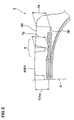
- Fig. 1 is a sectional view of a heavy duty tire of the present invention for a truck, a bus and the like.
- a heavy duty tire 1 comprises a carcass 6 extending from a tread portion 2 to a bead core 5 of a bead portion 4 through a sidewall portion 3, and a belt layer 7 disposed inside the tread portion 2 and outside the carcass 6.
- the carcass 6 comprises one or more (one, in this example) carcass ply 6A in which a carcass cord is arranged at an angle of 70 to 90° with respect to a circumferential direction of the tire.
- a metal cord such as steel is used as the carcass cord.
- the carcass ply 6A has a ply body 6a extending between the bead cores 5 and 5.
- the ply body 6a is provided at its opposite sides with turned up portions 6b which are turned up from inner side toward outer side around the bead core 5.
- a bead apex rubber 8 extending radially outward from the bead core 5 is disposed between the ply body 6a and the turned up portion 6b.
- the bead apex rubber 8 reinforces a portion of the tire from the bead portion 4 to the sidewall portion 3.
- the belt layer 7 comprises three or more belt plies using metal cords as belt cords.
- the belt layer 7 comprises four belt plies, i.e., a first belt ply 7A in which a steel cord is arranged radially innermost side at an angle of 60 ⁇ 15° with respect to the circumferential direction of the tire, and second to fourth belt plies 7B, 7C and 7D in which steel cords are arranged at an angle of 10 to 35° with respect to the circumferential direction of the tire.
- a ply width of the first belt ply 7A in the axial direction of the tire is smaller than a ply width of the second belt ply 7B and is substantially equal to a ply width of the third belt ply 7C.
- a ply width WB of the second belt ply 7B which is the greatest width is 0.80 to 0.95 times a tread ground-contact width WT, thereby reinforcing substantially the entire width of the tread portion 2 while providing a hoop effect and enhancing the rigidity of the tread.
- the fourth belt ply 7D having the narrowest width functions as a breaker which protects the first to third belt plies 7A to 7D and the carcass 6 from damage.
- the heavy duty tire 1 is provided at its tread portion 2 with a tread pattern having two or more longitudinal main grooves G continuously extending in the circumferential direction.
- the longitudinal main groove G is a groove having a groove width of 3mm or more.
- the longitudinal main groove G is straight or zigzag in shape (including wavy shape) and extends in the circumferential direction. It is preferable that the groove width is 5mm or more, and more preferably in a range of 7 to 10mm. It is preferable that a groove depth is 9mm or more, and more preferably in a range of 14.5 to 17.5mm.
- each the longitudinal main groove G comprises three grooves, i.e., an inner longitudinal main groove Gi disposed on the tire equator C, and outer longitudinal main grooves Go disposed on each side of the longitudinal main groove Gi.
- the outer longitudinal main groove Go constitutes axially outermost side shoulder groove Gs of the tire.
- a groove center line N of the shoulder groove Gs passes through the region Y which is separated from the tire equator C by a distance of 0.4 to 0.7 times a half of the ground-contact width of the tread WT/2. That is, a distance Kn of the groove center line N from the tire equator C is in a range of 0.4 to 0.7 times the half of the ground-contact width of the tread WT/2.
- the tread portion 2 is divided into a tread center portion Yc which is inside the shoulder groove Gs and a tread shoulder portion Ys which is outside the shoulder groove Gs.
- the shoulder groove Gs is a zigzag groove
- a center of amplitude of the zigzag is the groove center line N.
- the region Y is in a range of 0.5 to 0.7 times the half of the ground-contact width of the tread WT/2, and more preferably 0.5 to 0.65 times the half of the ground-contact width of the tread WT/2.
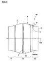
- a ground-contact surface shape 10 when a normal load is applied is limited as follows.
- the tangent X is inclined to a ground-contact length center 10N axially outward of the tire, i.e., toward + side.
- the tangent angle ⁇ is a new parameter devised by the present inventor, and it was found that the tangent angle ⁇ has a strong correlation with respect to the uneven wear, and the uneven wear is generated in a portion of the tire having a large tangent angle ⁇ . It is important for enhancing uneven wear resistance to limit the tangent angle 8.
- the ground-contact length at the ground-contact edge point Pd can be increased and thus, it is possible to suppress the unbalanced wear.
- the difference ( ⁇ 3- ⁇ 2) of the tangent angle is limited to a range of -10° or more to +10° or less, it is possible to equalize the proceeding of wear over the entire tread, and it is possible to suppress the unbalanced wear and the uneven wear such as orbital wear at the shoulder groove Gs, and to enhance the wear resistance over the entire range from the tire equator C to the tread ground-contact end E.
- a maximum value ⁇ max of the tangent angle ⁇ in the entire range from the tire equator C to the tread ground-contact end E is suppressed to 25° or less. If the tangent angle ⁇ exceeds 25°, abrupt uneven wear is generated in this exceeding portion. For example, if the exceeding portion is at the ground-contact edge E, unbalanced wear is generated, if the exceeding portion is in the region Y, orbital wear is generated, and if the exceeding portion is in the tread center portion Yc, center wear, punching wear and the like are generated.
- Fig. 5 shows one example of variation of the tangent angles ⁇ from the tire equator C to the tread ground-contact end E in tires (tire of the first invention) of embodiments A1 to A3 used in a wear test shown in Table 1.
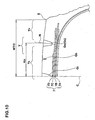
- a tread thickness between a profile line S of the tread surface ( "tread profile line S" hereinafter) and the second belt ply 7B in the normal internal pressure state is defined as T
- a tread thickness Ty in each position in the region Y is set in a range of not less than 0.91 times but not more than 1.05 times a tread thickness Tc at the position of the tire equator C
- a tread thickness Tb at a position of an outer end of the second belt ply 7B is set in a range of not less than 0.98 times but not more than 1.03 times the tread thickness Tc.
- the second belt ply 7B is formed of a single arc whose center is on the tire equator C
- the tread profile line S in the tread center portion Yc is formed of a projecting arc profile line Sl using a single or a plurality of arcs
- the tread profile line S in the tread shoulder portion Ys is formed of a substantially straight profile line S2.
- the first invention can suitably be applied to a general heavy duty tire and a tire having three longitudinal main grooves G.
- the second invention can suitably be applied to a tire for a dump truck used under a high load and a tire having four longitudinal main grooves G.
- the heavy duty tire 1 comprises four longitudinal main grooves G, i.e., inner longitudinal main grooves Gi disposed on each side of the tire equator C, and outer longitudinal main grooves Go disposed on the outside of the longitudinal main grooves Gi.
- a shoulder groove Gs which is the outer longitudinal main groove Go is formed in the region Y.
- the tangent angles ⁇ and ⁇ are new parameters devised by the present inventor, and these tangent angles are strongly related to the uneven wear, and optimizing the angles ⁇ and ⁇ is important for enhancing uneven wear resistance (equalizing the wear).
- the angle ⁇ exceeds 12°, the ground-contact pressure of the tread shoulder portion Ys is lowered and a load in the tread center portion Yc is excessively increased. Therefore, wear in the tread center portion Yc proceeds faster than the tread shoulder portion Ys, center wear proceeds, and the equalization of wear is deteriorated.
- the angle ⁇ is not more than 0°, the ground-contact pressure of the tread shoulder portion Ys is increased as compared with the tread center portion Yc. As a result, heat generation in the tread shoulder portion Ys is increased, and there is a tendency that peel-off damage is caused in the belt end by this temperature rise, and durability is deteriorated. Therefore, the angle ⁇ is preferably in a range of 5 to 12°.
- the angle ⁇ is limited to a range of not less than -3° but not more than the angle ⁇ , slip on the tread ground-contact end E can be reduced, and the unbalanced wear can be suppressed. If the angle ⁇ exceeds the angle ⁇ , a ground-contact length at the ground-contact edge point Pd becomes excessively short as compared with ground-contact lengths Lb and Lc at the groove-side edge points Pb and Pc of the shoulder groove Gs, and unbalanced wear is prone to be generated.
- the angle ⁇ is smaller than -3° on the other hand, the ground-contact pressure at the groove-side edge point Pc is lowered, the wear at the groove-side edge point Pc proceeds faster, and orbital wear is generated, or the ground-contact pressure of the entire tread shoulder portion Ys becomes extremely small, and center wear is generated. Therefore, it is preferable that the angle ⁇ is not less than 0°.
- a ratio La/Ld between a ground-contact length La at the equator point Pa and a ground-contact length Ld at the ground-contact edge point Pd is also important to limit a ratio La/Ld between a ground-contact length La at the equator point Pa and a ground-contact length Ld at the ground-contact edge point Pd to a range of more than 1.0 but not more than 1.20. If the ratio La/Ld exceeds 1.20, the ground-contact length Ld at the ground-contact edge point Pd becomes excessively short as compared with the ground-contact length La at the equator point Pa, and thereby slip is prone to be generated at the tread ground-contact end E irrespective of the value of the angle ⁇ .
- the ground-contact length L of the ground-contact surface shape 10 is gradually reduced axially outward of the tire, i.e., the tangent X at each point of the profile line F is inclined toward + side as in the first invention.
- a tread thickness smallest position Q where the tread thickness T between the tread profile line S and the second belt ply 7B becomes minimum value Tmin is provided in a region Z which is separated away from the tire equator C by a distance in a range of not less than 0.60 times but not more than 0.7 times the half of the ground-contact width of the tread. That is, a distance Kq from the tire equator C to the tread thickness smallest position Q is 0.60 to 0.7 times the half of the ground-contact width of the tread WT/2.
- the tread thickness T is increased from the tread thickness smallest position Q axially outward of the tire to a position of the outer end of the second belt ply 7B.
- the tread thickness T is increased to the tire equator C also axially inward of the tire from the tread thickness smallest position Q.
- the tread thickness Tc at the tire equator C is great as compared with the tread thickness Tb of the second belt ply 7B at its outer end, the tread thickness Tc may be equal to or smaller than Tb.
- the second belt ply 7B is formed of a single arc whose center is on the tire equator C.
- the tread profile line S in the tread center portion Yc is formed of the projecting arc profile line Sl using a single or a plurality of arcs, and the tread profile line S in the tread shoulder portion Ys is formed of the substantially straight profile line S2.
- the third invention can suitably be applied to a general heavy duty tire and a tire having three longitudinal main grooves G.
- the heavy duty tire 1 comprises three grooves, i.e., an inner longitudinal main groove Gi disposed on the tire equator C, and outer longitudinal main grooves Go disposed on each side of the longitudinal main groove Gi.
- the longitudinal main groove Go constitutes the axially outermost shoulder groove Gs.
- a longitudinal thin groove Gh having a width narrower than the longitudinal main groove G is formed between the inner and outer longitudinal main grooves Gi and Go is formed in this example, this longitudinal thin groove Gh may not be formed.
- the heavy duty tire 1 of the third invention in order to suppress the uneven wear and equalize the wear, in the profile line F of the ground-contact surface shape 10 as shown in Fig. 11,
- the angle ⁇ is preferably in a range of 5 to 12° and more preferably in a range of 8 to 11°.
- the angle ⁇ is set in a range of more than 0° but not more than 15°. If the angle ⁇ exceeds 15°, the ground-contact pressure near the groove-side edge point Pb becomes excessively small as compared with the ground-contact pressure near the groove-side edge point Pc, slip near the groove-side edge point Pb becomes great, and orbital wear is prone to be generated. If the angle ⁇ is not more than 0°, the ground-contact pressure at the tread center portion Yc becomes extremely great and the center wear is prone to be generated. Therefore, the angle ⁇ is preferably set in a range of 5° to 12° and more preferably in a range of 8 to 11°.
- the angle ⁇ is set in a range of not less than -5° but not more than the angle ⁇ . If the angle ⁇ is smaller than -5°, the ground-contact pressure near the groove-side edge point Pc is prone to be reduced, and orbital wear is generated near the groove-side edge point Pc at an early stage.
- the angle ⁇ exceeds the angle ⁇ , the ground-contact length Ld at the ground-contact edge point Pd becomes excessively small as compared with the ground-contact length Lb and Lc at the groove-side edge point Pb and the groove-side edge point Pc, respectively, and the unbalanced wear is prone to be generated. If the angle ⁇ becomes greater than the angle ⁇ , the ground-contact length Ld at the ground-contact edge point Pd becomes excessively small with respect to the ground-contact length Lc at the groove-side edge point Pc, and the unbalanced wear is prone to be generated likewise. Therefore, it is preferable that the angle ⁇ is not less than 0°.
- the angle ⁇ is 12° to 15° and the angle ⁇ is -5° to -3°, it is possible to exhibit the suppressing effect of the uneven wear like the second invention by controlling the angle ⁇ in a range of more than 0° but not more than 12°.
- the ground-contact surface shape 10 of the third invention may be obtained by a method which defines the thickness of the tread rubber, a method which defines the radius of curvature of the tread surface, a method which defines the radius of curvature of the belt layer, for example, or a method comprising a combination of these methods.
- the third invention like the first and second inventions, it is preferable to gradually reduce the ground-contact length L toward the outside in the axial direction of the tire, and it is preferable to set the ratio La/Ld of the ground-contact length La at the equator point Pa and the ground-contact length Ld at the ground-contact edge point Pd in a range of more than 1.0 but not more than 1.20.
- features 1) and 2) of the profile line F of the tire of the first invention are added to the heavy duty tire of the second invention, and that features 1) and 2) of the profile line F of the tire of the first invention are added to the heavy duty tire of the third invention.
- the heavy duty tires (tire size is 11R22.5) of the first invention having the internal structure shown in Fig. 1 were prototyped based on specs shown in Table 1, and wear of the prototyped tires was tested. A result of the test is shown in Table 1.
- Test tires were mounted on rims (22.5 ⁇ 7.50) and internal pressure (800kPa) was charged into the tires, and then the tires were attached to front wheels of a truck (2-2 ⁇ D type). The truck was allowed to run through a distance of 10,000km.
- a wear amount Zi in the inner longitudinal main groove Gi and a wear amount Zo in the longitudinal main groove Go (shoulder groove Gs) were measured, and ratios Zi/Zo were compared with each other.
- the ratio Zi/Zo is greater than 1.0, center wear tends to be generated, when the ratio Zi/Zo is smaller than 1.0, shoulder wear tends to be generated, and as the ratio Zi/Zo becomes closer to 1.0, equalization of wear becomes more excellent.
- the wear amount Zi was an average value of both the groove side edges of the inner longitudinal main groove Gi
- the wear amount Zo was an average value of both the groove side edges of the outer longitudinal main groove Go.
- drop amounts Z2 of tire equator-side side edge Go2 of the outer longitudinal main groove Go with respect to a reference arc R0 passing through three points, i.e., the tire equator C and the groove-side edges Go1 and Go1 were measured and compared with each other. The greater the value, the greater the orbital wear is.
- Drop amounts Z3 of the tread ground-contact edge E with respect to the reference arc R0 were measured and compared with each other. The greater the value, the greater the unbalanced wear is.
- Tread thickness Ty was measured at a position away from the tire equator by a distance of 0.6 times the half of the ground-contact width of the tread WT/2. (Others): A width of the shoulder groove is 12mm, a distance Kn of the groove center line is 0.54 times the half of the tread ground-contact width: WT/2.
- the heavy duty tires (tire size is 275/80R22.5) of the second invention having the internal structure shown in Fig. 1 were prototyped based on specs shown in Table 2, and wear of the prototyped tires was tested. A result of the test is shown in Table 2.
- Test tires were mounted on rims (22.5 ⁇ 7.50), and internal pressure (875kPa) was charged into the tires, and then the tires were attached to front wheels of a truck (2-2 ⁇ D type). The truck was allowed to run through a distance of 60, 000km. In the tires after running,
- the heavy duty tires (tire size is 11R22.5) of the third invention having the internal structure shown in Fig. 1 were prototyped based on specs shown in Table 1, and wear of the prototyped tires was tested. A result of the test is shown in Table 3.
- Test tires were mounted on rims (22.5 ⁇ 7.50), and internal pressure (700kPa) was charged into the tires, and then the tires were mounted to front wheels of a truck (2-2 ⁇ D type). The truck was allowed to run through a distance of 60, 000km. In the tires after running, like the above embodiment B,
- the profile line of the ground-contact surface shape is limited by its tangent angle ⁇ , angles ⁇ , ⁇ or ⁇ . Therefore, it is possible to effectively suppress uneven wear, such as unbalanced wear, orbital wear and center wear, and to achieve a high level of equalization of the wear.
- the profile line of the ground-contact surface shape is limited by tangent angle ⁇ and the like in each point of the profile line, it is possible to effectively suppress uneven wear, such as unbalanced wear, orbital wear and center wear, and to achieve a high level of equalization of the wear.
Landscapes
- Engineering & Computer Science (AREA)
- Mechanical Engineering (AREA)
- Tires In General (AREA)
Applications Claiming Priority (7)
| Application Number | Priority Date | Filing Date | Title |
|---|---|---|---|
| JP2001390013 | 2001-12-21 | ||
| JP2001390013A JP4392147B2 (ja) | 2001-12-21 | 2001-12-21 | 重荷重用タイヤ |
| JP2002013237 | 2002-01-22 | ||
| JP2002013237A JP3808778B2 (ja) | 2002-01-22 | 2002-01-22 | 重荷重用タイヤ |
| JP2002157877 | 2002-05-30 | ||
| JP2002157877 | 2002-05-30 | ||
| PCT/JP2002/013155 WO2003053722A1 (fr) | 2001-12-21 | 2002-12-16 | Pneu super-resistant |
Publications (3)
| Publication Number | Publication Date |
|---|---|
| EP1459909A1 true EP1459909A1 (fr) | 2004-09-22 |
| EP1459909A4 EP1459909A4 (fr) | 2009-11-04 |
| EP1459909B1 EP1459909B1 (fr) | 2011-05-18 |
Family
ID=27347986
Family Applications (1)
| Application Number | Title | Priority Date | Filing Date |
|---|---|---|---|
| EP02788847A Expired - Lifetime EP1459909B1 (fr) | 2001-12-21 | 2002-12-16 | Pneu super-resistant |
Country Status (5)
| Country | Link |
|---|---|
| US (1) | US7469731B2 (fr) |
| EP (1) | EP1459909B1 (fr) |
| CN (1) | CN1292928C (fr) |
| AU (1) | AU2002354498A1 (fr) |
| WO (1) | WO2003053722A1 (fr) |
Cited By (1)
| Publication number | Priority date | Publication date | Assignee | Title |
|---|---|---|---|---|
| EP3023266A4 (fr) * | 2013-08-06 | 2017-04-12 | Sumitomo Rubber Industries, Ltd. | Pneumatique |
Families Citing this family (19)
| Publication number | Priority date | Publication date | Assignee | Title |
|---|---|---|---|---|
| DE60229882D1 (de) * | 2002-01-16 | 2008-12-24 | Sumitomo Rubber Ind | Hochleistungsreifen |
| US7905936B2 (en) * | 2004-04-30 | 2011-03-15 | Donaldson Company, Inc. | Filter arrangements; housing; assemblies; and, methods |
| DE602005020621D1 (de) * | 2004-06-23 | 2010-05-27 | Bridgestone Corp | Luftreifen |
| JP4486592B2 (ja) * | 2005-12-29 | 2010-06-23 | 住友ゴム工業株式会社 | 重荷重用タイヤ |
| JP4866177B2 (ja) * | 2006-08-28 | 2012-02-01 | 住友ゴム工業株式会社 | 重荷重用タイヤ |
| US9370971B2 (en) | 2010-12-29 | 2016-06-21 | Compagnie Generale Des Etablissements Michelin | Methods for retreading a tire |
| US20130276944A1 (en) * | 2010-12-29 | 2013-10-24 | Compagnie Generale Des Etablissements Michelin | Custom pre-cured retread |
| US9751365B2 (en) * | 2011-09-13 | 2017-09-05 | The Goodyear Tire & Rubber Company | High mileage truck tire tread |
| KR101730943B1 (ko) | 2012-10-10 | 2017-05-11 | 요코하마 고무 가부시키가이샤 | 공기입 타이어 |
| US10183531B2 (en) * | 2012-10-10 | 2019-01-22 | The Yokohama Rubber Co., Ltd. | Pneumatic tire |
| KR101710070B1 (ko) * | 2012-10-10 | 2017-03-08 | 요코하마 고무 가부시키가이샤 | 공기입 타이어 |
| CN104955659B (zh) * | 2012-11-30 | 2017-06-20 | 株式会社普利司通 | 充气轮胎 |
| CN104870219B (zh) * | 2012-12-28 | 2017-03-22 | 横滨橡胶株式会社 | 充气轮胎 |
| CN104870208B (zh) * | 2012-12-28 | 2017-03-08 | 横滨橡胶株式会社 | 充气轮胎 |
| JP5360333B1 (ja) * | 2013-02-25 | 2013-12-04 | 横浜ゴム株式会社 | 空気入りタイヤ |
| JP6114731B2 (ja) * | 2014-10-31 | 2017-04-12 | 住友ゴム工業株式会社 | 空気入りタイヤ |
| DE202017002619U1 (de) * | 2016-05-20 | 2017-08-04 | Lg Electronics Inc. | Staubsauger |
| JP2020083133A (ja) * | 2018-11-28 | 2020-06-04 | Toyo Tire株式会社 | 空気入りタイヤ |
| FR3105096B1 (fr) * | 2019-12-19 | 2022-11-25 | Michelin & Cie | Bande de roulement de pneumatique pour véhicule lourd comprenant des protubérances anti-bruit et chasse-pierres |
Family Cites Families (19)
| Publication number | Priority date | Publication date | Assignee | Title |
|---|---|---|---|---|
| JP2617713B2 (ja) * | 1987-03-26 | 1997-06-04 | 横浜ゴム株式会社 | 重荷重用空気入りラジアルタイヤ |
| JPH01141104A (ja) * | 1987-11-27 | 1989-06-02 | Sumitomo Rubber Ind Ltd | 重荷重用空気入りラジアルタイヤ |
| JPH02155805A (ja) * | 1988-12-08 | 1990-06-14 | Bridgestone Corp | 氷上走行性能に優れたスタッドレスタイヤ |
| JP2544532B2 (ja) * | 1990-06-15 | 1996-10-16 | 住友ゴム工業株式会社 | 重荷重用タイヤ |
| US5769978A (en) * | 1990-07-27 | 1998-06-23 | Compagnie Generale Des Etablissments Michelin - Michelin & Cie | Tire having a thread with lateral ribs the surface of which is radially recessed with respect to the other ribs |
| JP3121391B2 (ja) * | 1991-09-19 | 2000-12-25 | 株式会社ブリヂストン | 重荷重用空気入りタイヤ |
| JP2672049B2 (ja) | 1991-10-09 | 1997-11-05 | 住友ゴム工業株式会社 | 重荷重用タイヤ |
| JP3343633B2 (ja) | 1993-12-17 | 2002-11-11 | 東洋ゴム工業株式会社 | 重荷重用空気入りタイヤ |
| US5647925A (en) * | 1993-12-17 | 1997-07-15 | Toyo Tire & Rubber Co., Ltd. | Pneumatic tire for heavy-loaded vehicles, with resistance to river wear |
| US5660652A (en) * | 1995-07-14 | 1997-08-26 | The Goodyear Tire & Rubber Company | Truck tire and tread for steer axles |
| US5616195A (en) * | 1995-08-28 | 1997-04-01 | The Goodyear Tire & Rubber Company | Low aspect ratio truck tire |
| JP3254166B2 (ja) * | 1997-05-16 | 2002-02-04 | 住友ゴム工業株式会社 | 重荷重用ラジアルタイヤ |
| KR20010014009A (ko) * | 1997-06-20 | 2001-02-26 | 폴 겔리 | 벨트와 원주방향 리브를 포함하는 공압 타이어 |
| JPH11245622A (ja) * | 1998-03-04 | 1999-09-14 | Yokohama Rubber Co Ltd:The | 空気入りタイヤ |
| CN1216753C (zh) * | 1999-03-18 | 2005-08-31 | 倍耐力轮胎公司 | 用于中型/重型运输车辆的轮胎 |
| KR100689213B1 (ko) * | 1999-03-18 | 2007-03-09 | 피렐리 타이어 소시에떼 퍼 아찌오니 | 중/대형 수송 차량용 타이어 |
| JP4015623B2 (ja) * | 2001-12-14 | 2007-11-28 | 住友ゴム工業株式会社 | 重荷重用タイヤ |
| DE60229882D1 (de) * | 2002-01-16 | 2008-12-24 | Sumitomo Rubber Ind | Hochleistungsreifen |
| US20040112492A1 (en) * | 2002-12-12 | 2004-06-17 | John Kotanides | Tire for inter-city buses and motor coaches |
-
2002
- 2002-12-16 WO PCT/JP2002/013155 patent/WO2003053722A1/fr not_active Ceased
- 2002-12-16 CN CNB028236408A patent/CN1292928C/zh not_active Expired - Fee Related
- 2002-12-16 AU AU2002354498A patent/AU2002354498A1/en not_active Abandoned
- 2002-12-16 US US10/495,363 patent/US7469731B2/en not_active Expired - Fee Related
- 2002-12-16 EP EP02788847A patent/EP1459909B1/fr not_active Expired - Lifetime
Cited By (2)
| Publication number | Priority date | Publication date | Assignee | Title |
|---|---|---|---|---|
| EP3023266A4 (fr) * | 2013-08-06 | 2017-04-12 | Sumitomo Rubber Industries, Ltd. | Pneumatique |
| US10195900B2 (en) | 2013-08-06 | 2019-02-05 | Sumitomo Rubber Industries, Ltd. | Pneumatic tire with specified tread thickness distribution and specified section width in relation to bead diameter |
Also Published As
| Publication number | Publication date |
|---|---|
| EP1459909A4 (fr) | 2009-11-04 |
| AU2002354498A1 (en) | 2003-07-09 |
| WO2003053722A1 (fr) | 2003-07-03 |
| CN1292928C (zh) | 2007-01-03 |
| CN1596196A (zh) | 2005-03-16 |
| US7469731B2 (en) | 2008-12-30 |
| EP1459909B1 (fr) | 2011-05-18 |
| US20050016656A1 (en) | 2005-01-27 |
Similar Documents
| Publication | Publication Date | Title |
|---|---|---|
| EP1459909B1 (fr) | Pneu super-resistant | |
| JP6111134B2 (ja) | 空気入りタイヤ | |
| EP3424751B1 (fr) | Pneumatique | |
| US6991015B2 (en) | Pneumatic tire having non-symmetric pattern | |
| EP3023268B1 (fr) | Pneu pour poids lourd | |
| EP2230102B1 (fr) | Bandage pneumatique | |
| US7036541B2 (en) | Pneumatic tire | |
| EP1454767B1 (fr) | Pneu poids lourd | |
| US6082424A (en) | Heavy duty radial tire | |
| US7918256B2 (en) | Heavy duty tire having ground contacting face at 70% and 100% maximum tire load | |
| EP1466759B1 (fr) | Pneu super-resistant | |
| EP3321103B1 (fr) | Pneu pour poids lourd | |
| EP2889159B1 (fr) | Pneu pour poids lourds | |
| EP3332991B1 (fr) | Pneumatique | |
| EP1433623B1 (fr) | Bandage pneumatique radial pour poids-lourds | |
| EP3415342B1 (fr) | Pneu pour fonctionnement intensif | |
| EP1712377A1 (fr) | Pneumatique | |
| EP3360699B1 (fr) | Pneu pour poids lourd et son procédé de fabrication | |
| US6474381B1 (en) | Pneumatic tire including axial grooves | |
| US20010003998A1 (en) | Heavy duty tire | |
| CN108284711B (zh) | 充气轮胎 | |
| EP1024032B1 (fr) | Bandage pneumatique | |
| JP3808778B2 (ja) | 重荷重用タイヤ | |
| JP2004161202A (ja) | 重荷重用空気入りタイヤ | |
| JP2023010598A (ja) | タイヤ |
Legal Events
| Date | Code | Title | Description |
|---|---|---|---|
| PUAI | Public reference made under article 153(3) epc to a published international application that has entered the european phase |
Free format text: ORIGINAL CODE: 0009012 |
|
| 17P | Request for examination filed |
Effective date: 20040421 |
|
| AK | Designated contracting states |
Kind code of ref document: A1 Designated state(s): AT BE BG CH CY CZ DE DK EE ES FI FR GB GR IE IT LI LU MC NL PT SE SI SK TR |
|
| AX | Request for extension of the european patent |
Extension state: AL LT LV MK RO |
|
| A4 | Supplementary search report drawn up and despatched |
Effective date: 20091001 |
|
| 17Q | First examination report despatched |
Effective date: 20100122 |
|
| GRAP | Despatch of communication of intention to grant a patent |
Free format text: ORIGINAL CODE: EPIDOSNIGR1 |
|
| GRAS | Grant fee paid |
Free format text: ORIGINAL CODE: EPIDOSNIGR3 |
|
| GRAA | (expected) grant |
Free format text: ORIGINAL CODE: 0009210 |
|
| AK | Designated contracting states |
Kind code of ref document: B1 Designated state(s): DE FR GB |
|
| REG | Reference to a national code |
Ref country code: GB Ref legal event code: FG4D |
|
| REG | Reference to a national code |
Ref country code: DE Ref legal event code: R096 Ref document number: 60240095 Country of ref document: DE Effective date: 20110630 |
|
| PLBE | No opposition filed within time limit |
Free format text: ORIGINAL CODE: 0009261 |
|
| STAA | Information on the status of an ep patent application or granted ep patent |
Free format text: STATUS: NO OPPOSITION FILED WITHIN TIME LIMIT |
|
| 26N | No opposition filed |
Effective date: 20120221 |
|
| REG | Reference to a national code |
Ref country code: DE Ref legal event code: R097 Ref document number: 60240095 Country of ref document: DE Effective date: 20120221 |
|
| PGFP | Annual fee paid to national office [announced via postgrant information from national office to epo] |
Ref country code: GB Payment date: 20141210 Year of fee payment: 13 |
|
| REG | Reference to a national code |
Ref country code: FR Ref legal event code: PLFP Year of fee payment: 14 |
|
| GBPC | Gb: european patent ceased through non-payment of renewal fee |
Effective date: 20151216 |
|
| PG25 | Lapsed in a contracting state [announced via postgrant information from national office to epo] |
Ref country code: GB Free format text: LAPSE BECAUSE OF NON-PAYMENT OF DUE FEES Effective date: 20151216 |
|
| REG | Reference to a national code |
Ref country code: FR Ref legal event code: PLFP Year of fee payment: 15 |
|
| REG | Reference to a national code |
Ref country code: FR Ref legal event code: PLFP Year of fee payment: 16 |
|
| PGFP | Annual fee paid to national office [announced via postgrant information from national office to epo] |
Ref country code: FR Payment date: 20181120 Year of fee payment: 17 |
|
| PGFP | Annual fee paid to national office [announced via postgrant information from national office to epo] |
Ref country code: DE Payment date: 20191203 Year of fee payment: 18 |
|
| PG25 | Lapsed in a contracting state [announced via postgrant information from national office to epo] |
Ref country code: FR Free format text: LAPSE BECAUSE OF NON-PAYMENT OF DUE FEES Effective date: 20191231 |
|
| REG | Reference to a national code |
Ref country code: DE Ref legal event code: R119 Ref document number: 60240095 Country of ref document: DE |
|
| PG25 | Lapsed in a contracting state [announced via postgrant information from national office to epo] |
Ref country code: DE Free format text: LAPSE BECAUSE OF NON-PAYMENT OF DUE FEES Effective date: 20210701 |