EP1459934A2 - Projecteur pour véhicules - Google Patents
Projecteur pour véhicules Download PDFInfo
- Publication number
- EP1459934A2 EP1459934A2 EP04004763A EP04004763A EP1459934A2 EP 1459934 A2 EP1459934 A2 EP 1459934A2 EP 04004763 A EP04004763 A EP 04004763A EP 04004763 A EP04004763 A EP 04004763A EP 1459934 A2 EP1459934 A2 EP 1459934A2
- Authority
- EP
- European Patent Office
- Prior art keywords
- cooling element
- light source
- headlamp according
- reflector
- headlamp
- Prior art date
- Legal status (The legal status is an assumption and is not a legal conclusion. Google has not performed a legal analysis and makes no representation as to the accuracy of the status listed.)
- Withdrawn
Links
Images

Classifications
-
- F—MECHANICAL ENGINEERING; LIGHTING; HEATING; WEAPONS; BLASTING
- F21—LIGHTING
- F21V—FUNCTIONAL FEATURES OR DETAILS OF LIGHTING DEVICES OR SYSTEMS THEREOF; STRUCTURAL COMBINATIONS OF LIGHTING DEVICES WITH OTHER ARTICLES, NOT OTHERWISE PROVIDED FOR
- F21V29/00—Protecting lighting devices from thermal damage; Cooling or heating arrangements specially adapted for lighting devices or systems
- F21V29/50—Cooling arrangements
- F21V29/70—Cooling arrangements characterised by passive heat-dissipating elements, e.g. heat-sinks
- F21V29/74—Cooling arrangements characterised by passive heat-dissipating elements, e.g. heat-sinks with fins or blades
- F21V29/77—Cooling arrangements characterised by passive heat-dissipating elements, e.g. heat-sinks with fins or blades with essentially identical diverging planar fins or blades, e.g. with fan-like or star-like cross-section
- F21V29/773—Cooling arrangements characterised by passive heat-dissipating elements, e.g. heat-sinks with fins or blades with essentially identical diverging planar fins or blades, e.g. with fan-like or star-like cross-section the planes containing the fins or blades having the direction of the light emitting axis
-
- F—MECHANICAL ENGINEERING; LIGHTING; HEATING; WEAPONS; BLASTING
- F21—LIGHTING
- F21S—NON-PORTABLE LIGHTING DEVICES; SYSTEMS THEREOF; VEHICLE LIGHTING DEVICES SPECIALLY ADAPTED FOR VEHICLE EXTERIORS
- F21S41/00—Illuminating devices specially adapted for vehicle exteriors, e.g. headlamps
- F21S41/10—Illuminating devices specially adapted for vehicle exteriors, e.g. headlamps characterised by the light source
- F21S41/12—Illuminating devices specially adapted for vehicle exteriors, e.g. headlamps characterised by the light source characterised by the type of emitted light
- F21S41/13—Ultraviolet light; Infrared light
-
- F—MECHANICAL ENGINEERING; LIGHTING; HEATING; WEAPONS; BLASTING
- F21—LIGHTING
- F21S—NON-PORTABLE LIGHTING DEVICES; SYSTEMS THEREOF; VEHICLE LIGHTING DEVICES SPECIALLY ADAPTED FOR VEHICLE EXTERIORS
- F21S45/00—Arrangements within vehicle lighting devices specially adapted for vehicle exteriors, for purposes other than emission or distribution of light
- F21S45/10—Protection of lighting devices
-
- F—MECHANICAL ENGINEERING; LIGHTING; HEATING; WEAPONS; BLASTING
- F21—LIGHTING
- F21S—NON-PORTABLE LIGHTING DEVICES; SYSTEMS THEREOF; VEHICLE LIGHTING DEVICES SPECIALLY ADAPTED FOR VEHICLE EXTERIORS
- F21S45/00—Arrangements within vehicle lighting devices specially adapted for vehicle exteriors, for purposes other than emission or distribution of light
- F21S45/40—Cooling of lighting devices
- F21S45/47—Passive cooling, e.g. using fins, thermal conductive elements or openings
- F21S45/48—Passive cooling, e.g. using fins, thermal conductive elements or openings with means for conducting heat from the inside to the outside of the lighting devices, e.g. with fins on the outer surface of the lighting device
-
- F—MECHANICAL ENGINEERING; LIGHTING; HEATING; WEAPONS; BLASTING
- F21—LIGHTING
- F21V—FUNCTIONAL FEATURES OR DETAILS OF LIGHTING DEVICES OR SYSTEMS THEREOF; STRUCTURAL COMBINATIONS OF LIGHTING DEVICES WITH OTHER ARTICLES, NOT OTHERWISE PROVIDED FOR
- F21V29/00—Protecting lighting devices from thermal damage; Cooling or heating arrangements specially adapted for lighting devices or systems
- F21V29/50—Cooling arrangements
- F21V29/70—Cooling arrangements characterised by passive heat-dissipating elements, e.g. heat-sinks
- F21V29/80—Cooling arrangements characterised by passive heat-dissipating elements, e.g. heat-sinks with pins or wires
-
- F—MECHANICAL ENGINEERING; LIGHTING; HEATING; WEAPONS; BLASTING
- F21—LIGHTING
- F21S—NON-PORTABLE LIGHTING DEVICES; SYSTEMS THEREOF; VEHICLE LIGHTING DEVICES SPECIALLY ADAPTED FOR VEHICLE EXTERIORS
- F21S45/00—Arrangements within vehicle lighting devices specially adapted for vehicle exteriors, for purposes other than emission or distribution of light
- F21S45/30—Ventilation or drainage of lighting devices
- F21S45/33—Ventilation or drainage of lighting devices specially adapted for headlamps
-
- F—MECHANICAL ENGINEERING; LIGHTING; HEATING; WEAPONS; BLASTING
- F21—LIGHTING
- F21S—NON-PORTABLE LIGHTING DEVICES; SYSTEMS THEREOF; VEHICLE LIGHTING DEVICES SPECIALLY ADAPTED FOR VEHICLE EXTERIORS
- F21S45/00—Arrangements within vehicle lighting devices specially adapted for vehicle exteriors, for purposes other than emission or distribution of light
- F21S45/40—Cooling of lighting devices
- F21S45/42—Forced cooling
- F21S45/43—Forced cooling using gas
-
- F—MECHANICAL ENGINEERING; LIGHTING; HEATING; WEAPONS; BLASTING
- F21—LIGHTING
- F21V—FUNCTIONAL FEATURES OR DETAILS OF LIGHTING DEVICES OR SYSTEMS THEREOF; STRUCTURAL COMBINATIONS OF LIGHTING DEVICES WITH OTHER ARTICLES, NOT OTHERWISE PROVIDED FOR
- F21V7/00—Reflectors for light sources
- F21V7/0008—Reflectors for light sources providing for indirect lighting
-
- F—MECHANICAL ENGINEERING; LIGHTING; HEATING; WEAPONS; BLASTING
- F21—LIGHTING
- F21Y—INDEXING SCHEME ASSOCIATED WITH SUBCLASSES F21K, F21L, F21S and F21V, RELATING TO THE FORM OR THE KIND OF THE LIGHT SOURCES OR OF THE COLOUR OF THE LIGHT EMITTED
- F21Y2115/00—Light-generating elements of semiconductor light sources
- F21Y2115/10—Light-emitting diodes [LED]
-
- Y—GENERAL TAGGING OF NEW TECHNOLOGICAL DEVELOPMENTS; GENERAL TAGGING OF CROSS-SECTIONAL TECHNOLOGIES SPANNING OVER SEVERAL SECTIONS OF THE IPC; TECHNICAL SUBJECTS COVERED BY FORMER USPC CROSS-REFERENCE ART COLLECTIONS [XRACs] AND DIGESTS
- Y10—TECHNICAL SUBJECTS COVERED BY FORMER USPC
- Y10S—TECHNICAL SUBJECTS COVERED BY FORMER USPC CROSS-REFERENCE ART COLLECTIONS [XRACs] AND DIGESTS
- Y10S362/00—Illumination
- Y10S362/80—Light emitting diode
Definitions
- the invention relates to a headlamp for a vehicle, in particular according to the projection principle, with a reflector, a light source in the focal point of the reflector and a transparent pane.
- headlamps are known from the German patent application DE 100 47 207 A1 and DE 100 27 018 A1.
- a halogen light source which emits both visible light and infrared radiation, arranged.
- the halogen light source is mounted from the rear in a central recess in the reflector. It emits the light either directly or indirectly via a reflection on the reflector in the direction of the transparent pane.
- the invention has for its object to provide a headlamp, which shows a good light output and which shows good resistance.
- the invention relates to a headlamp for a vehicle according to the preamble of patent claim 1, wherein a semiconductor light source is arranged as a light source in the focal point of the reflector, which emits exclusively or substantially infrared radiation.
- the headlamp is provided with a cooling element which is thermally connected to the semiconductor light source and extends from the semiconductor light source to the transparent pane and either protrudes into the pane or even pierces it.
- This special arrangement and design of the light source with cooling element ensures that an efficient dissipation of the heat which arises during the generation of the light by the semiconductor light source is given away from the light source.
- the cooling element dissipates the heat from the light source by, on the one hand, even as a cooling element has a considerable heat capacity and thereby leads to a cooling of the light source, which is ensured by the thermal coupling. This heat will then deliver to the atmosphere surrounding the cooling element either only in the interior of the headlight or in the vicinity of the headlight.
- the optional puncturing of the cooling element through the transparent pane ensures that the airstream or the surroundings of the spotlight leads to a decrease in the temperature of the cooling element and thus of the semiconductor light source. This is achieved by heat from the cooling element in the area in front of the transparent pane is delivered to the environment. This is the case regularly during operation of the headlamp, since the surroundings of the headlamp have a significantly lower temperature than the semiconductor light source. Cooling of the semiconductor light source is of particular importance for the functional capability of the semiconductor light source, since, in contrast to a conventional halogen light source, it may not be heated above a critical temperature, which is regularly in the region of 120 ° C. or below.
- the cooling element or the semiconductor light source in the headlight makes it possible to keep the semiconductor light source of the headlamp in a safe temperature state.
- semiconductor light sources semiconductor laser elements as well as LEDs, which can be configured as individual light sources or in the form of an array, have proven to be particularly suitable.
- the arrangement of the semiconductor light source according to the invention makes it possible to dispense with large holes or recesses in the reflector for placement or introduction of halogen light sources in the reflector, resulting in that the reflector wholly or largely for the reflection of the light emitted by the light sources for Available. These reflection properties are of particular importance in the region in which the central axis of the, at least substantially, rotationally symmetrical reflector pierces the reflector.
- the inventive design of the headlight makes it possible to increase the reflective surface and thereby significantly improve the light output of the headlamp.
- the light output is also increased by the fact that the light source is not a halogen light source or an incandescent light source is used, but a semiconductor light source that allow a very bright and efficient emission of light or in the form of radiation in predetermined frequency ranges.
- the provision of the cooling element ensures that the semiconductor light source is not only a very effective short-term source of light for the headlight according to the invention, but that this property is also given over a longer period of time.
- the position of the cooling element and thus also the position of the light source defined by the intrusion into or through the cooling element through the disc which creates the possibility, in whole or in part to additional or complex brackets for fixing the Location of the light source in the area of the focus to dispense.
- additional brackets in contrast to consuming disturbing brackets for the light source by the formation of the cooling element according to the invention sufficient or unnecessary.
- IR LEDs infrared radiation emitting light-emitting diodes
- IR LEDs which emit radiation exclusively in the non-visible region of the electromagnetic radiation, that is to say in the region of the infrared radiation and not in the region of the visible light
- a night vision device or in an arrangement for improving the view with active infrared illumination, with a camera for detecting the infrared Radiation illuminated environment and a display to display the captured by the camera infrared image data to act.
- Such an arrangement with such an infrared radiation headlamp according to the invention makes it possible to illuminate the surroundings very reliably and permanently by means of infrared radiation and thus a very information-rich reproduction of the environmental data acquired by the camera. An early and permanent recognition even under difficult circumstances, especially at night or fog, is made possible by the headlamp according to the invention.
- the cooling element extends along the central axis of the reflector.
- This design of the cooling element ensures that there is no significant additional shadowing of the emitted light by the cooling element. This is achieved by the fact that the cooling element is due to its arrangement in the region of the central axis, which forms the axis of rotational symmetry of the at least substantially rotationally symmetrical reflector, and thereby comes to lie wholly or substantially in the shadow of the semiconductor light source.
- the semiconductor light source which lies in the focal point and thus on the central axis, emits their, in particular infrared, radiation in the direction of the reflector, which due to its design as a reflector of a headlight deflects the reflected radiation such that it emits at least substantially parallel to the central axis becomes.
- This small or nonexistent additional shading is particularly low if the cooling element, as in a particularly preferred embodiment of the invention, is of rod-shaped design, in particular of constant diameter. This is on the one hand a very low shading and on the other hand given a cost-effective production with good heat dissipation due to the massive design of the cooling element in the form of a rod. This leads to a particularly durable and effective design of a headlight.
- the cooling element shows one or more substantially planar elements, which are arranged in particular radially extending in the reflector.
- These substantially planar elements can be formed independently of a, in particular rod-shaped, extending along the central axis of the cooling element. Due to the planar design of or part of the cooling element, a particularly effective heat release to the environment of the cooling element is achieved.
- This environment may be on the one hand the interior of the reflector, on the other hand, but also the environment of the headlamp, in particular the space on the side facing away from the light source of the transparent pane.
- This planar design ensures that the cooling element can very effectively dissipate heat from the semiconductor light element and thus carry it off, which leads to overheating of the semiconductor light element being prevented.
- the service life and luminous efficacy of the semiconductor element are ensured to a particular degree.
- a particularly advantageous embodiment of the cooling element with a plurality of radially extending, flat elements is created in that these several flat elements are arranged rotationally symmetrical about the central axis. It has proven particularly useful to provide three, four or five planar elements that are arranged in a star shape. By this rotationally symmetrical, in particular star-shaped design a mechanically very rigid and stable arrangement of the planar elements to create a secure fixation of the semiconductor light source in the region of the focal point is created, which in particular benefits from the fact that the cooling element is very effectively fixed in the disc.
- the sheet-like elements may have a uniform substantially constant material thickness over their surface, resulting in a very cost-effective design of the cooling element.
- they can also be designed with variable material thickness, that is, the material thickness can increase with increasing distance from the central axis or decrease or increase or decrease in areas.
- the most suitable design of the flat elements with a constant or differing material thickness is selected. In particular, it has been proven, areas that particularly are vibration prone to form with a greater material thickness, which ensures the existence and durability of the headlamp.
- the cooling element which is in particular partially rod-shaped and / or flat formed completely or in significant parts mirrored, which leads to the fact that arranged by the beam path of the headlamp cooling element no significant absorption of the infrared radiation or of visible light is present, resulting in a very effective high-intensity design of a headlight.
- the light portions reflected by the silvering are regularly of only small circumference, since the cooling element extends parallel or along the central axis and thus along the light propagation direction of the light reflected by the reflector.
- This mirrored design makes it possible to compensate for manufacturing tolerances in a particularly pleasant way and to prevent deviations from the ideal design or arrangement of the cooling element or the light source in the headlamp with reflector leads to a significant impairment of the light output.
- the cooling element of a particularly thermally conductive material, in particular of metal.
- This aluminum, copper, silver and iron or an alloy thereof have proven particularly useful.
- These metals show a particularly pronounced processability, a good heat transport capability and in addition a large heat capacity.
- these metallic cooling elements are characterized by a rapid effective dissipation of heat from the semiconductor light source, which in particular due to the high heat capacity, and on the other hand by the good heat transfer properties and thus the ability to deliver the heat in particular to the environment of the headlamp.
- the cooling element in particular the rod-shaped cooling element in the form of a metallic shell around an interior, wherein the interior is filled by the metal sodium, whereas the shell in particular of aluminum, copper, silver and iron or an alloy is formed therefrom.
- the cooling element projects beyond the disc only insignificantly or flatly with the disc. This ensures that, when a sufficient cooling surface is obtained in the region of the side of the transparent pane facing away from the semiconductor light source, there is no danger to passers by projecting parts of the headlight in the event of a collision of the vehicle with the headlamp according to the invention. It has proven particularly useful to let the edge region of the projecting beyond the disc part of the cooling element slidably pass into the disc and thereby to realize a planar and non-stage transition from the cooling element into the disc. This ensures that a hanging of a passer-by or other object is largely excluded. In addition, it is also ensured that a strong soiling of the disc is prevented, as well as a particularly favorable aerodynamic shape of the disc is provided with cooling element, which can be integrated in a particularly appealing manner in the shape of the entire vehicle.
- a particular disk-shaped heat sink on the side of the pane facing away from the semiconductor light source and to connect it thermally and mechanically to the cooling element. This ensures that the cooling surface, which is in contact with the surroundings of the headlamp, is increased and thus the cooling effect of the cooling element with heat sink on the semiconductor light source is particularly enhanced.
- the particular disc-shaped Heatsink preferably in its edge region so tapered that it merges fluently in the disc.
- the semiconductor light source in the form of an array of a plurality of individual light sources, which are arranged together on a support, which has a sufficient thermal conductivity, and which is thermally connected to the cooling element.
- This design of the semiconductor light source as an array with carrier ensures that a compact, bright and inexpensive to produce light source is created, which ensures a temperature compensation on the carrier and allows safe and effective dissipation of heat through the thermally connected cooling element.
- a particularly bright, effective vehicle headlights is given, which ensures a large-area thermal coupling with the cooling element in the case of a planar design of the carrier and thereby enables a low operating temperature of the semiconductor light source and thus a high efficiency and a long lifetime of the semiconductor light source.
- the array is preferably arranged completely on one side of the planar carrier and emits its particular infrared radiation in the direction of the reflector, which reflects the particular infrared radiation and then radiates parallel to the central axis and thus along the cooling element.
- the arrangement of the individual light sources or of a substantial part of the individual light sources on one side of the planar support and the arrangement or thermal coupling of the cooling element with the other side of the planar support a spatial separation and thus a functional separation of the different components of the headlamp is created which leads to a permanent, bright design of the headlamp.
- cooling element It has also proven particularly effective to realize the power supply of the semiconductor light sources via the cooling element.
- this can be achieved by arranging conductor tracks on, on or in the cooling element, as on the other hand it is also possible for individual parts of the cooling element to realize electrically conductive and isolated from each other and to use these electrically conductive parts isolated from each other as a conductive electrical lines for the power supply of the light source.
- the cooling element for supplying energy to the light source, it is possible to provide the central region of the reflector, ie the trough-like region of the reflector, with a closed reflecting surface and not to impair its function by means of electrical leads or connections. This training creates the opportunity to realize a very effective headlamp.
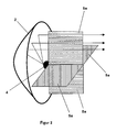
- FIG. 1 shows a headlight 1 which has a reflector 2 and a transparent pane 3.
- the reflector 2 is designed such that a semiconductor light source 4 arranged in its focal point causes a reflection of the emitted radiation during the emission of infrared radiation in the direction of the reflector 2 in such a way that the reflected radiation passes essentially parallel through the transparent disc is emitted.
- This headlight 1 shows the operation of a vehicle headlight.
- the semiconductor light source 4 is realized as an infrared radiation emitting semiconductor light emitting diode. This is mechanically and thermally connected to a cooling element 5.
- the cooling element 5 is realized in the form of a rod of constant diameter and extends from the light source 4 along the central axis of the rotationally symmetrical reflector 2 to the transparent pane 3 and through it. The cooling element 5 extends beyond even in the vicinity of the headlamp. 1
- the rod-shaped cooling element 5 has substantially the same cross-section as the semiconductor light source 4. This makes it possible that the rod-shaped cooling element 5 comes to lie substantially in the shadow of the semiconductor light source 4. This ensures that the radiation reflected by the reflector 2, which propagates substantially parallel to the center axis of the reflector 2 and thus along the rod-shaped cooling element 5, is not hindered or only to a limited extent by the cooling element 5. This ensures that an additional shading by the cooling element 5 is not or only to a small extent given and thus a very good efficiency of the headlamp 1 is given.
- the rod-shaped fastening element 5 is fixed in the transparent pane 3, which results in its position being fixed in the reflector 2 and thus in the headlight 1, which leads to the fact that the position of the semiconductor light source 4, which with the cooling element 5 mechanically and thermally fixed is fixed.
- additional fasteners for the light source 4 can by the invention omitted in Figure 1 structure.
- the cooling element 5 is formed of copper, which is coated with a chromium layer.
- the chrome plating creates a mirrored surface which, to a great extent, prevents undesirable absorption of the reflected light and thereby largely reduces possible impairment of the light output by the cooling element.
- the use of copper ensures that the heat which is realized by the semiconductor light source 4 in operation is transferred very quickly and efficiently into the cooling element 5, is guided through the transparent pane and emitted to the environment.
- the protrusion of the cooling element 5 through the transparent pane 3 with the projection of the pane 3 ensures that the airstream to which the headlight according to the invention is exposed during operation of the vehicle results in considerable cooling of the part 3 of the cooling element 5 projecting beyond the pane 3, which ensures that the heat is dissipated from the light source 4 via the rod-shaped cooling element 5 and discharged to the environment.
- Overheating of the semiconductor light source 4, for example by reaching a temperature of 150 ° C. can thus be largely prevented, which on the one hand has a very positive effect on the efficiency of the semiconductor light source 4 and on the other hand, on the life of the semiconductor light source 4.
- the embodiment of the invention shown in Figure 1 by a good heat dissipation and thus by a high efficiency of the light source 4 characterized by increased durability.
- the illustrated embodiment shows a very good light output, which is based in particular on the fact that the mirror surface of the reflector 2 has no significant interruptions, especially in the central region of the reflector, that is, the region closest to the semiconductor light source 4, and is based on that the cooling element 5 causes its formation and arrangement no or only a very small additional shading of the reflected radiation.
- FIG. 2 shows another embodiment of the headlamp according to the invention.
- the design of the headlamp according to the invention according to Figure 1 will be discussed.
- the representation of corresponding or identical embodiments of individual components of the headlamp is dispensed with.
- the incompletely illustrated reflector 2 shows the shape of a paraboloid or a hyperboloid, in whose focal point the IR semiconductor light source 4 is arranged.
- the cooling element which is composed of four flat surfaces 5a.
- the four flat surfaces 5a are realized in the form of rectangular plates, which are arranged radially around the central axis, that is to say the rotational symmetry axis of the reflector 2.
- the four flat plates 5a of the cooling element are arranged in a star shape and rotationally symmetrical about the central axis. They are oriented so that the radiation reflected by the reflector 2 is parallel to the planar elements 5a.
- the light source 4 is in the region of a corner of the individual sheet-like elements 5a, which abut each other in this corner, mechanically and thermally firmly connected to each other.
- This thermal and solid mechanical connection ensures that the heat of the light source is dissipated into the planar elements 5 a and the heat is then released to the surroundings of the planar elements 5 a on the one hand inside the reflector 2 on the other hand outside the headlight. Due to the extensive training this is guaranteed to a special degree.
- This heat transfer ensures that the light source 4 does not overheat.
- the flat, plate-shaped elements 5a show a low material thickness, so that the shading is very low.
- the surfaces are mirrored, so that absorption of the infrared radiation is possible only to a very limited extent.
- the mirror coating is chosen in different colors from the mirroring of the reflector. This makes it possible to realize in addition to the particular light output of the headlamp according to the invention also in addition a particularly attractive appearance.
- planar elements 5a Of the four planar elements 5a, two are separated from one another and are electrically insulated and electrically conductive. These two planar elements 5a are used to supply the electric power to the light source 4. The provision of additional electrical supply lines can thus be dispensed with and thus further shading by additional electrical supply lines be prevented. This leads to a very bright headlight.
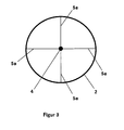
- FIG 3 the view of the disc 3 is shown from the front.
- the disc 3 is pierced by the four flat, planar elements 5a, which together form the cooling element.
- the four planar elements 5a are arranged in a star-shaped rotationally symmetrical about the central axis of the headlamp and the reflector 2.
- the planar elements 5a are thermally and mechanically connected in the middle with the light source 4.
- a coupling is provided, in which the planar elements 5a are firmly connected to the surrounding reflector 2.
Landscapes
- Engineering & Computer Science (AREA)
- General Engineering & Computer Science (AREA)
- Non-Portable Lighting Devices Or Systems Thereof (AREA)
- Arrangement Of Elements, Cooling, Sealing, Or The Like Of Lighting Devices (AREA)
Applications Claiming Priority (2)
| Application Number | Priority Date | Filing Date | Title |
|---|---|---|---|
| DE10311853A DE10311853B4 (de) | 2003-03-17 | 2003-03-17 | Scheinwerfer für ein Fahrzeug |
| DE10311853 | 2003-03-17 |
Publications (2)
| Publication Number | Publication Date |
|---|---|
| EP1459934A2 true EP1459934A2 (fr) | 2004-09-22 |
| EP1459934A3 EP1459934A3 (fr) | 2008-02-20 |
Family
ID=32797945
Family Applications (1)
| Application Number | Title | Priority Date | Filing Date |
|---|---|---|---|
| EP04004763A Withdrawn EP1459934A3 (fr) | 2003-03-17 | 2004-03-02 | Projecteur pour véhicules |
Country Status (4)
| Country | Link |
|---|---|
| US (1) | US7281823B2 (fr) |
| EP (1) | EP1459934A3 (fr) |
| JP (1) | JP3859159B2 (fr) |
| DE (1) | DE10311853B4 (fr) |
Cited By (11)
| Publication number | Priority date | Publication date | Assignee | Title |
|---|---|---|---|---|
| DE102006059904A1 (de) * | 2006-12-19 | 2008-06-26 | Hella Kgaa Hueck & Co. | Fahrzeugleuchte |
| DE102007016439A1 (de) * | 2007-04-05 | 2008-10-09 | Volkswagen Ag | LED-Leuchte für ein Kraftfahrzeug |
| DE102007016442A1 (de) * | 2007-04-05 | 2008-10-09 | Volkswagen Ag | LED-Leuchte für ein Kraftfahrzeug |
| DE102008003915A1 (de) * | 2008-01-10 | 2009-07-23 | Heinrich-Beck-Institut Gmbh | LED-Fernscheinwerfer |
| DE102006034353B4 (de) * | 2005-07-28 | 2013-01-03 | Koito Manufacturing Co., Ltd. | Fahrzeugleuchte |
| DE102011119379A1 (de) * | 2011-11-25 | 2013-05-29 | Volkswagen Aktiengesellschaft | Beleuchtungsvorrichtung für ein Kraftfahrzeug |
| WO2013134804A1 (fr) * | 2012-03-12 | 2013-09-19 | Zizala Lichtsysteme Gmbh | Phare de véhicule avec source lumineuse à laser |
| EP2722579A1 (fr) * | 2012-10-19 | 2014-04-23 | Automotive Lighting Reutlingen GmbH | Phare de véhicule automobile avec source de lumière et dispositif de refroidissement pour la source de lumière |
| US10125943B2 (en) | 2014-03-12 | 2018-11-13 | Volkswagen Aktiengesellschaft | Motor vehicle and motor vehicle headlamp with a front housing |
| DE102017209003A1 (de) * | 2017-05-30 | 2018-12-06 | Bayerische Motoren Werke Aktiengesellschaft | Beleuchtungsvorrichtung für ein Kraftfahrzeug |
| US11603976B2 (en) | 2021-02-08 | 2023-03-14 | Volkswagen Aktiengesellschaft | Motor vehicle headlamp and method for operating a motor vehicle headlamp |
Families Citing this family (25)
| Publication number | Priority date | Publication date | Assignee | Title |
|---|---|---|---|---|
| JP3976063B2 (ja) * | 2003-10-31 | 2007-09-12 | 豊田合成株式会社 | 発光装置 |
| US7255264B2 (en) * | 2004-04-24 | 2007-08-14 | De Leon Hilary Laing | Cellular phone-based automatic payment system |
| TWI236571B (en) * | 2004-09-21 | 2005-07-21 | Coretronic Corp | A cooling air gathering plate |
| JP2006140084A (ja) * | 2004-11-15 | 2006-06-01 | Koito Mfg Co Ltd | 車両用灯具 |
| JP2006310204A (ja) * | 2005-04-28 | 2006-11-09 | Toyoda Gosei Co Ltd | Led灯具 |
| US7585096B2 (en) * | 2005-05-18 | 2009-09-08 | Visteon Global Technologies, Inc. | Compound trough reflector for LED light sources |
| CN101495802B (zh) * | 2006-07-28 | 2011-08-10 | 皇家飞利浦电子股份有限公司 | 照明模块 |
| US7854529B2 (en) * | 2006-08-30 | 2010-12-21 | Underwater Kinetics, Inc. | Bezel-integrated thermal conductors |
| TW200925513A (en) * | 2007-12-11 | 2009-06-16 | Prodisc Technology Inc | LED lamp structure for reducing multiple shadows |
| CN101660715B (zh) * | 2008-08-25 | 2013-06-05 | 富准精密工业(深圳)有限公司 | 发光二极管灯具 |
| US8760043B2 (en) | 2008-11-18 | 2014-06-24 | Koninklijke Philips N.V. | LED-based electric lamp |
| BRPI0916006A2 (pt) | 2008-11-18 | 2015-11-03 | Koninkl Philips Electronics Nv | "lâmpada elétrica" |
| US20100246203A1 (en) * | 2009-03-27 | 2010-09-30 | North American Lighting, Inc. | System and method for exterior lighting of vehicles |
| JP2010262767A (ja) * | 2009-04-30 | 2010-11-18 | Koito Mfg Co Ltd | 車輌用灯具 |
| DE102009021353A1 (de) | 2009-05-14 | 2009-12-24 | Daimler Ag | Scheinwerfer |
| US8646941B1 (en) | 2010-06-14 | 2014-02-11 | Humanscale Corporation | Lighting apparatus and method |
| JP5869223B2 (ja) * | 2011-02-09 | 2016-02-24 | 株式会社小糸製作所 | 車両用前照灯 |
| KR101262610B1 (ko) * | 2011-11-09 | 2013-05-08 | 기아자동차주식회사 | 차량용 램프구조 |
| US9677730B2 (en) * | 2014-06-18 | 2017-06-13 | Ag World Corp. | Vehicular light system |
| US9829179B2 (en) * | 2014-06-26 | 2017-11-28 | Phillip Walesa | Parabolic quadrant LED light fixture |
| US9772074B1 (en) | 2016-10-07 | 2017-09-26 | Rafail Bronstein | Laser diodes based illumination device |
| JP6545201B2 (ja) * | 2017-01-13 | 2019-07-17 | 本田技研工業株式会社 | 鞍乗り型車両の車体前部構造 |
| KR102441571B1 (ko) * | 2017-10-12 | 2022-09-08 | 현대자동차주식회사 | 차량의 리어 램프 장치 |
| JP7144633B1 (ja) | 2022-02-10 | 2022-09-29 | 山崎 明美 | Led照明装置 |
| JP7220969B1 (ja) | 2022-02-10 | 2023-02-13 | 山崎 明美 | Led照明装置 |
Family Cites Families (17)
| Publication number | Priority date | Publication date | Assignee | Title |
|---|---|---|---|---|
| US1950918A (en) * | 1932-04-08 | 1934-03-13 | Walter M Kaefer | Combined headlight lens and reflector |
| DE3929955A1 (de) * | 1989-09-08 | 1991-03-14 | Inotec Gmbh Ges Fuer Innovativ | Lichtstrahler |
| US5174646A (en) * | 1990-12-06 | 1992-12-29 | The Regents Of The University Of California | Heat transfer assembly for a fluorescent lamp and fixture |
| DE4335244B4 (de) * | 1993-10-15 | 2006-10-19 | Daimlerchrysler Ag | Anordnung zur Bildaufnahme |
| US5785418A (en) * | 1996-06-27 | 1998-07-28 | Hochstein; Peter A. | Thermally protected LED array |
| US6045240A (en) * | 1996-06-27 | 2000-04-04 | Relume Corporation | LED lamp assembly with means to conduct heat away from the LEDS |
| US6441943B1 (en) * | 1997-04-02 | 2002-08-27 | Gentex Corporation | Indicators and illuminators using a semiconductor radiation emitter package |
| DE29910417U1 (de) * | 1999-06-15 | 1999-08-12 | Sidler GmbH & Co, 72072 Tübingen | Reflektorleuchte |
| US6367949B1 (en) * | 1999-08-04 | 2002-04-09 | 911 Emergency Products, Inc. | Par 36 LED utility lamp |
| DE20002565U1 (de) * | 2000-02-14 | 2001-06-28 | Zumtobel Staff Ges.M.B.H., Dornbirn | Leuchtdiodenanordnung mit Reflektor |
| DE10027018B4 (de) * | 2000-05-31 | 2010-09-09 | Robert Bosch Gmbh | Fahrzeugscheinwerfer nach dem Projektionsprinzip und Beleuchtungseinrichtung eines Fahrzeugs mit wenigstens einem solchen Scheinwerfer |
| DE10034767A1 (de) * | 2000-07-18 | 2002-05-02 | Hella Kg Hueck & Co | Leuchte |
| DE10047207A1 (de) * | 2000-09-23 | 2002-04-11 | Hella Kg Hueck & Co | Scheinwerfer für Fahrzeuge |
| DE10055462C2 (de) * | 2000-11-09 | 2003-07-31 | Daimler Chrysler Ag | Einrichtung für ein Fahrzeugleuchtensystem und Verwendung der Einrichtung |
| US6682211B2 (en) * | 2001-09-28 | 2004-01-27 | Osram Sylvania Inc. | Replaceable LED lamp capsule |
| US6909376B2 (en) * | 2002-03-14 | 2005-06-21 | Mark Rennick | Integrated vehicle light and object proximity sensor assembly |
| DE10256102B4 (de) * | 2002-11-29 | 2005-09-15 | Daimlerchrysler Ag | Fahrzeugscheinwerfer und Verfahren zum Betrieb eines solchen |
-
2003
- 2003-03-17 DE DE10311853A patent/DE10311853B4/de not_active Expired - Fee Related
-
2004
- 2004-03-02 EP EP04004763A patent/EP1459934A3/fr not_active Withdrawn
- 2004-03-16 US US10/801,349 patent/US7281823B2/en not_active Expired - Fee Related
- 2004-03-17 JP JP2004075861A patent/JP3859159B2/ja not_active Expired - Lifetime
Cited By (15)
| Publication number | Priority date | Publication date | Assignee | Title |
|---|---|---|---|---|
| DE102006034353B4 (de) * | 2005-07-28 | 2013-01-03 | Koito Manufacturing Co., Ltd. | Fahrzeugleuchte |
| DE102006059904B4 (de) * | 2006-12-19 | 2017-02-16 | Hella Kgaa Hueck & Co. | Fahrzeugleuchte |
| DE102006059904A1 (de) * | 2006-12-19 | 2008-06-26 | Hella Kgaa Hueck & Co. | Fahrzeugleuchte |
| DE102007016439A1 (de) * | 2007-04-05 | 2008-10-09 | Volkswagen Ag | LED-Leuchte für ein Kraftfahrzeug |
| DE102007016442A1 (de) * | 2007-04-05 | 2008-10-09 | Volkswagen Ag | LED-Leuchte für ein Kraftfahrzeug |
| DE102007016439B4 (de) * | 2007-04-05 | 2017-08-17 | Volkswagen Ag | LED-Leuchte für ein Kraftfahrzeug |
| DE102008003915A1 (de) * | 2008-01-10 | 2009-07-23 | Heinrich-Beck-Institut Gmbh | LED-Fernscheinwerfer |
| DE102011119379A1 (de) * | 2011-11-25 | 2013-05-29 | Volkswagen Aktiengesellschaft | Beleuchtungsvorrichtung für ein Kraftfahrzeug |
| WO2013134804A1 (fr) * | 2012-03-12 | 2013-09-19 | Zizala Lichtsysteme Gmbh | Phare de véhicule avec source lumineuse à laser |
| US9611994B2 (en) | 2012-03-12 | 2017-04-04 | Zkw Group Gmbh | Vehicle headlight with laser light source |
| EP2722579A1 (fr) * | 2012-10-19 | 2014-04-23 | Automotive Lighting Reutlingen GmbH | Phare de véhicule automobile avec source de lumière et dispositif de refroidissement pour la source de lumière |
| DE102012219162A1 (de) * | 2012-10-19 | 2014-05-08 | Automotive Lighting Reutlingen Gmbh | Kraftfahrzeugscheinwerfer mit Lichtquelle und einer Kühleinrichtung für die Lichtquelle |
| US10125943B2 (en) | 2014-03-12 | 2018-11-13 | Volkswagen Aktiengesellschaft | Motor vehicle and motor vehicle headlamp with a front housing |
| DE102017209003A1 (de) * | 2017-05-30 | 2018-12-06 | Bayerische Motoren Werke Aktiengesellschaft | Beleuchtungsvorrichtung für ein Kraftfahrzeug |
| US11603976B2 (en) | 2021-02-08 | 2023-03-14 | Volkswagen Aktiengesellschaft | Motor vehicle headlamp and method for operating a motor vehicle headlamp |
Also Published As
| Publication number | Publication date |
|---|---|
| DE10311853B4 (de) | 2005-03-24 |
| JP2004281407A (ja) | 2004-10-07 |
| DE10311853A1 (de) | 2004-10-07 |
| JP3859159B2 (ja) | 2006-12-20 |
| EP1459934A3 (fr) | 2008-02-20 |
| US7281823B2 (en) | 2007-10-16 |
| US20040202005A1 (en) | 2004-10-14 |
Similar Documents
| Publication | Publication Date | Title |
|---|---|---|
| DE10311853B4 (de) | Scheinwerfer für ein Fahrzeug | |
| EP1721102B1 (fr) | Lampe | |
| AT512588B1 (de) | Lichtquellenmodul mit Laserlichtquelle sowie Fahrzeugscheinwerfer | |
| EP1995514B1 (fr) | Unité d'éclairage | |
| EP2363320B1 (fr) | Phare frontal doté d'un système de réflexion DEL doté d'une fonction de feux de brouillard et de feux de jour | |
| EP1828671B1 (fr) | Dispositif d'eclairage dote d'au moins une diode electroluminescente et phare de vehicule | |
| DE102007021865B4 (de) | Beleuchtungseinrichtung für ein Fahrzeug | |
| EP2459925B1 (fr) | Lampe | |
| DE102011080489B4 (de) | Kraftfahrzeugscheinwerfer | |
| DE102004017454A1 (de) | Scheinwerfer für Fahrzeuge | |
| DE102007023786B4 (de) | Scheinwerfermodul und Scheinwerferanordnung für ein Kraftfahrzeug mit innen reflektierendem, lichtdurchlässigem Element | |
| DE102009021353A1 (de) | Scheinwerfer | |
| DE102004046764A1 (de) | Fahrzeugscheinwerfer | |
| EP2886936A1 (fr) | Agent lumineux et lampe de véhicule automobile équipée de celui-ci | |
| DE102005051248B4 (de) | Lichteinheit, insbesondere für ein Kraftfahrzeug | |
| EP2131101A1 (fr) | Lampe | |
| EP2722579A1 (fr) | Phare de véhicule automobile avec source de lumière et dispositif de refroidissement pour la source de lumière | |
| EP1840455B1 (fr) | Ensemble d'éclairage pour véhicule avec au moins deux sources lumineuses | |
| DE10160052A1 (de) | Fahrzeugleuchte | |
| EP2375136A1 (fr) | Lampe de véhicule automobile | |
| DE102011084890A1 (de) | Lichtmodul einer Beleuchtungseinrichtung eines Kraftfahrzeugs | |
| CN209084661U (zh) | 车辆用灯具 | |
| WO2008049381A1 (fr) | Dispositif d'éclairage | |
| WO2012028170A1 (fr) | Phare pour un véhicule | |
| DE102007042625A1 (de) | Leuchtenanordnung |
Legal Events
| Date | Code | Title | Description |
|---|---|---|---|
| PUAI | Public reference made under article 153(3) epc to a published international application that has entered the european phase |
Free format text: ORIGINAL CODE: 0009012 |
|
| AK | Designated contracting states |
Kind code of ref document: A2 Designated state(s): AT BE BG CH CY CZ DE DK EE ES FI FR GB GR HU IE IT LI LU MC NL PL PT RO SE SI SK TR |
|
| AX | Request for extension of the european patent |
Extension state: AL LT LV MK |
|
| RAP1 | Party data changed (applicant data changed or rights of an application transferred) |
Owner name: DAIMLERCHRYSLER AG |
|
| RAP1 | Party data changed (applicant data changed or rights of an application transferred) |
Owner name: DAIMLER AG |
|
| PUAL | Search report despatched |
Free format text: ORIGINAL CODE: 0009013 |
|
| AK | Designated contracting states |
Kind code of ref document: A3 Designated state(s): AT BE BG CH CY CZ DE DK EE ES FI FR GB GR HU IE IT LI LU MC NL PL PT RO SE SI SK TR |
|
| AX | Request for extension of the european patent |
Extension state: AL LT LV MK |
|
| RIC1 | Information provided on ipc code assigned before grant |
Ipc: F21W 101/10 20060101ALN20080115BHEP Ipc: F21S 8/10 20060101ALI20080115BHEP Ipc: F21V 29/00 20060101ALI20080115BHEP Ipc: B60Q 1/04 20060101AFI20040623BHEP |
|
| 17P | Request for examination filed |
Effective date: 20080314 |
|
| AKX | Designation fees paid |
Designated state(s): DE FR GB IT NL |
|
| 17Q | First examination report despatched |
Effective date: 20081104 |
|
| STAA | Information on the status of an ep patent application or granted ep patent |
Free format text: STATUS: THE APPLICATION HAS BEEN WITHDRAWN |
|
| 18W | Application withdrawn |
Effective date: 20120717 |