EP1459955A1 - Transportvorrichtung für eine Last und passende Befestigungsvorrichtung - Google Patents
Transportvorrichtung für eine Last und passende Befestigungsvorrichtung Download PDFInfo
- Publication number
- EP1459955A1 EP1459955A1 EP03405186A EP03405186A EP1459955A1 EP 1459955 A1 EP1459955 A1 EP 1459955A1 EP 03405186 A EP03405186 A EP 03405186A EP 03405186 A EP03405186 A EP 03405186A EP 1459955 A1 EP1459955 A1 EP 1459955A1
- Authority
- EP
- European Patent Office
- Prior art keywords
- straps
- chassis
- branches
- hand
- load
- Prior art date
- Legal status (The legal status is an assumption and is not a legal conclusion. Google has not performed a legal analysis and makes no representation as to the accuracy of the status listed.)
- Granted
Links
- 125000006850 spacer group Chemical group 0.000 claims description 9
- 238000010521 absorption reaction Methods 0.000 claims description 2
- 230000003014 reinforcing effect Effects 0.000 claims description 2
- 230000035939 shock Effects 0.000 claims description 2
- 238000010276 construction Methods 0.000 description 8
- 210000001624 hip Anatomy 0.000 description 4
- 230000002829 reductive effect Effects 0.000 description 4
- 238000013461 design Methods 0.000 description 3
- 239000000463 material Substances 0.000 description 3
- 230000036961 partial effect Effects 0.000 description 3
- 230000002787 reinforcement Effects 0.000 description 3
- 239000004744 fabric Substances 0.000 description 2
- 238000004519 manufacturing process Methods 0.000 description 2
- 210000004197 pelvis Anatomy 0.000 description 2
- 238000012360 testing method Methods 0.000 description 2
- 235000017166 Bambusa arundinacea Nutrition 0.000 description 1
- 235000017491 Bambusa tulda Nutrition 0.000 description 1
- 241001330002 Bambuseae Species 0.000 description 1
- 229920000271 Kevlar® Polymers 0.000 description 1
- 235000015334 Phyllostachys viridis Nutrition 0.000 description 1
- XAGFODPZIPBFFR-UHFFFAOYSA-N aluminium Chemical compound [Al] XAGFODPZIPBFFR-UHFFFAOYSA-N 0.000 description 1
- 229910052782 aluminium Inorganic materials 0.000 description 1
- 230000008485 antagonism Effects 0.000 description 1
- 238000013459 approach Methods 0.000 description 1
- 239000011425 bamboo Substances 0.000 description 1
- 230000015572 biosynthetic process Effects 0.000 description 1
- 230000001419 dependent effect Effects 0.000 description 1
- 238000011161 development Methods 0.000 description 1
- 238000006073 displacement reaction Methods 0.000 description 1
- 230000000694 effects Effects 0.000 description 1
- 239000011152 fibreglass Substances 0.000 description 1
- 230000002427 irreversible effect Effects 0.000 description 1
- 239000004761 kevlar Substances 0.000 description 1
- 230000000670 limiting effect Effects 0.000 description 1
- 238000012986 modification Methods 0.000 description 1
- 230000004048 modification Effects 0.000 description 1
- 235000020004 porter Nutrition 0.000 description 1
- 230000002028 premature Effects 0.000 description 1
- 230000000135 prohibitive effect Effects 0.000 description 1
- 230000002035 prolonged effect Effects 0.000 description 1
- 230000000717 retained effect Effects 0.000 description 1
- 239000007787 solid Substances 0.000 description 1
- 238000003786 synthesis reaction Methods 0.000 description 1
- 229920002994 synthetic fiber Polymers 0.000 description 1
- 238000013519 translation Methods 0.000 description 1
- 210000000689 upper leg Anatomy 0.000 description 1
- 239000002023 wood Substances 0.000 description 1
Images


Classifications
-
- A—HUMAN NECESSITIES
- A45—HAND OR TRAVELLING ARTICLES
- A45F—TRAVELLING OR CAMP EQUIPMENT: SACKS OR PACKS CARRIED ON THE BODY
- A45F3/00—Travelling or camp articles; Sacks or packs carried on the body
- A45F3/04—Sacks or packs carried on the body by means of two straps passing over the two shoulders
-
- A—HUMAN NECESSITIES
- A45—HAND OR TRAVELLING ARTICLES
- A45F—TRAVELLING OR CAMP EQUIPMENT: SACKS OR PACKS CARRIED ON THE BODY
- A45F3/00—Travelling or camp articles; Sacks or packs carried on the body
- A45F3/14—Carrying-straps; Pack-carrying harnesses
-
- B—PERFORMING OPERATIONS; TRANSPORTING
- B62—LAND VEHICLES FOR TRAVELLING OTHERWISE THAN ON RAILS
- B62B—HAND-PROPELLED VEHICLES, e.g. HAND CARTS OR PERAMBULATORS; SLEDGES
- B62B1/00—Hand carts having only one axis carrying one or more transport wheels; Equipment therefor
- B62B1/18—Hand carts having only one axis carrying one or more transport wheels; Equipment therefor in which the load is disposed between the wheel axis and the handles, e.g. wheelbarrows
- B62B1/20—Hand carts having only one axis carrying one or more transport wheels; Equipment therefor in which the load is disposed between the wheel axis and the handles, e.g. wheelbarrows involving parts being collapsible, attachable, detachable or convertible
-
- B—PERFORMING OPERATIONS; TRANSPORTING
- B62—LAND VEHICLES FOR TRAVELLING OTHERWISE THAN ON RAILS
- B62B—HAND-PROPELLED VEHICLES, e.g. HAND CARTS OR PERAMBULATORS; SLEDGES
- B62B5/00—Accessories or details specially adapted for hand carts
- B62B5/06—Hand moving equipment, e.g. handle bars
- B62B5/068—Connections to the body for moving the cart, e.g. harnesses
-
- A—HUMAN NECESSITIES
- A45—HAND OR TRAVELLING ARTICLES
- A45F—TRAVELLING OR CAMP EQUIPMENT: SACKS OR PACKS CARRIED ON THE BODY
- A45F3/00—Travelling or camp articles; Sacks or packs carried on the body
- A45F3/04—Sacks or packs carried on the body by means of two straps passing over the two shoulders
- A45F2003/045—Sacks or packs carried on the body by means of two straps passing over the two shoulders and one additional strap around the waist
-
- B—PERFORMING OPERATIONS; TRANSPORTING
- B62—LAND VEHICLES FOR TRAVELLING OTHERWISE THAN ON RAILS
- B62B—HAND-PROPELLED VEHICLES, e.g. HAND CARTS OR PERAMBULATORS; SLEDGES
- B62B5/00—Accessories or details specially adapted for hand carts
- B62B5/0023—Arrangements for carrying as a back-pack
Definitions
- the present invention relates to a load transport device according to the preamble of independent claim 1.
- This device can be towed by a user, directly, that is to say by the hands of the latter (or possibly be pushed in this way), or indirectly, that is to say by being connected thereto by means of an appropriate fastening device responding to the preamble of independent claim 14.
- the central problem posed by the type of device in question lies in the comfort and convenience of use, while the construction of the device must be simple and rational and inexpensive to manufacture. It is all the more difficult to solve since it is polymorphic, in the sense that it contains a series of components each constituting a sub-problem, and that a partial solution of a sub-problem can be prohibitive for a partial solution of another component of the problem.
- the lighter the chassis will be, the easier will be the handling of the device, its wearing and its traction.
- said chassis is solid and rigid.
- this comfort problem also arises for the attachment device, when the user calls on it to connect to the transport device to tow it. It is therefore appropriate that this attachment device is ergonomic, practical and pleasant to wear, while helping to maintain the balance of the assembly. This without sacrificing aesthetics.
- FR-A-2,775,878 discloses a frame formed by two longitudinal slats extending symmetrically with respect to a median plane, one or more reinforcing crosspieces and a support-spacer.
- the lower ends are close together so as to be spaced apart from each other only a small distance and are connected by a support device on the ground, for example a shaft carrying a wheel whose plane is included in said median plane.
- These slats open in the direction of the upper ends, each of which carries a support piece intended to come against the wearer's hips, the two pieces being connected together by a belt.
- the load rests on the support spacer, the wearer in any case passing the straps by his shoulders.
- US-4,664,395 discloses a device for transporting loads comprising a trolley or chassis-support and a harness.
- the chassis is made up of two beams and several crosspieces and is fitted with a pair of foldable crutches.
- the side members meet at their lower ends, near which a wheel fitted with brakes is arranged.
- the harness consists, on the one hand, of a pair of lower and upper belts arranged respectively around waist and torso, and a pair of suspenders, and, on the other hand, a dorsal structure formed by two tubes.
- the harness further comprises, in particular a case or more generally a fixing intended to receive a brake lever similar to that of a bicycle, this lever being connected to the wheel or, more precisely to a caliper carrying the brake linings, by a cable passing over the user's shoulder.
- a brake lever similar to that of a bicycle
- the two aforementioned belts and, on the other hand, in its upper zone, the upper ends of the chassis of the transport device.
- the harness is fairly complex and heavy, therefore expensive, but also unsightly, while its wearing proves difficult to say the least, constituting more of a yoke, so much so that the user will quickly abandon it and, with him, the whole device.
- the transport device itself, its design is such that both its balance in use and its rigidity are insufficient.
- the purpose of the present invention is to provide a truly effective and optimal solution, which is at the same time very elegant and attractive, thereby overcoming the drawbacks affecting known devices.
- the transport device according to the invention ensures, in particular due to the crossing of the lines of force, which are ideally distributed, an optimal balance; it combines strength and lightness, rigidity and flexibility, efficiency and simplicity of manufacture, convenience of use and aesthetics.
- the attachment device in the form of a belt or harness, it adds its share to the comfort of use.
- its connection to the transport device is located such that a risk of the latter tipping over, even in situations involving rotation or rocking of the body, is in principle eliminated.
- a tendency to swing that is to say a movement back and forth when walking, is almost canceled, or at least, the amplitude of such a movement will remain, in the worst of cases, extremely limited.
- the attachment device will allow the user, in many situations, to keep your hands free, this, unlike known devices.
- the user will place his hands on the handles of the device, to be ready, at any time, to neutralize any disturbing force.
- the devices according to the invention thus offer a range of advantages which have been proven during the testing of prototypes. It meets the most drastic requirements of hikers, but is equally suited to a very large audience to which it can be offered at a relatively low price, while distinguishing itself by a most advantageous quality / price index.
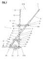
- These parts are connected together in an area where the branches of each V meet or intersect, in the occurrence at a crossing point 4 constituting the common vertex of the two Vs, while the pair of branches of each V opens and extends opposite each other (always in said plane P H ), on either side of a plane P V orthogonal to the plane P H , to form, according to the example, an asymmetric X with respect to the latter.
- the dimensions of the parts 2, 3, that is to say of the corresponding Vs, are defined by the heights H 1 and H 2 (H 2 being advantageously greater than H 1 ), as well as by the angles ⁇ and ⁇ , these two angles being advantageously equal to each other ( Figure 4).
- the chassis of the carriage 1 comprises two longitudinal members 5, 6 passing one over / under the other and connected together by a fixing member 41 whose axis 41A corresponds at least approximately to the line of intersection of the plane P V with a plane P M , the latter being a median or bisector plane of the parts 2, 3.
- This axis 41A contains by definition point 4, intersection of the three planes P H , P V and P M and crossing point, and, depending on the construction, point of contact of said beams with one another.
- These beams are preferably composed of tubes 7, 8 and telescopic elements 9, 10 extending in an adjustable manner the branches of the upper part 3, the ends of which are provided with handles 11, 12.
- the carriage is undeformable, while that the connecting means 41 of axis 41A is subjected to a minimum of stresses, since in this crossing point, the structure is reinforced by the superposition of the side members which absorb the forces.
- These crosspieces fill a double function, since they make it possible to stiffen the structure and at the same time constitute, with a portion of the pipes 7, 8 that they delimit that they delimit in the crossing zone, a seat or bearing area 19 for a load 16.
- the term delimit is not to be understood in the strict sense; the load can of course extend beyond the crosspieces 14, 15, or on the contrary occupy only part of the area 19]. In all cases, the load takes place in said crossing zone of the parts 2, 3 , which is particularly non-deformable and rigid.
- the load 16 is materialized, in the different figures by a backpack provided with straps 17 and moored to the frame by means of straps 18 (see in particular Figure 3).
- the load can be quickly and easily attached to the nacelle by a simple set of crossed straps - see FIG. 2A.
- the crosspieces 14, 15 in fact allow the arrangement of a nacelle of general reference 60.
- This nacelle comprises a canvas 61 in the shape of a trapezoid, with reinforced edges 62 and provided, at its four corners, with lugs 68 allowing its attachment to said said sleepers by fasteners 64.
- the load can be moored to the nacelle thanks to three straps.
- straps 65, 66 are fixed on and under the fabric 61 by lugs 67.
- the straps 65, 66 pass partially around the crosspieces 14, 15 respectively and are arranged in the direction of the plane P M.
- a strap 68 extends in the direction of the plane P V , therefore orthogonally to the straps 65, 66, and is retained on the carriage 1 by the central fixing member 41.
- This strap 68 therefore passes under the structure of the carriage in order to be folded down around the edges 62 of the fabric 61.
- the ends of the straps are provided with tightening loops 69.
- the support device on the ground, of general reference 20.
- the ends of the branches of the V of this part 2 are connected together by a support element 21 consisting of a shaft of axis 21A on which a wheel 22 is mounted, this shaft extending above the tube 8 and below the tube 7.
- the shaft 21 extends below of the two tubes 7 and 8.
- a protection and reinforcement bar 50 extends under a part of the tube 7, between the crosspiece 14 and the lower end of this tube, and also passes under the shaft 21. It is connected to the tube 7 and to the shaft 21 by fixing means 41.
- a protection and reinforcement bar 51 is disposed in a similar manner above a part of the tube 8, from the cross member 14 to the lower end of this tube, and joins the shaft 21 from above. It is connected to the latter and to the tube 8 by fixing means 41.
- the bar 51 also provides better aesthetics in the event of the spacer arrangement 43; 43 '( Figures 1 and 2, see below).
- the support device 20 can be executed according to different variants.
- it is possible to provide more than one wheel as can be seen in FIGS. 3 to 8, where this device comprises two wheels, arranged either inside the branches of the V of the lower part 2 (FIGS. 3 to 6), or outside these branches ( Figures 7 and 8).
- this device comprises two wheels, arranged either inside the branches of the V of the lower part 2 (FIGS. 3 to 6), or outside these branches ( Figures 7 and 8).
- H 1 and H 2 so that their H 1 / H 2 ratio lies within a range of values [0.25 - 0.35].
- the distance between the handles 11, 12 (line segment supported by the line 21B which will be discussed later) of the upper part 3 it goes without saying that it is defined in any event in such a way that said handles are located on the right and left of the user, in the position shown in FIG. 13 and without the user experiencing any discomfort (distance of the order of 0.60 m, which is somewhat greater than a average pelvic width).
- additional bores are provided (see FIG.
- these means consist of spacers of defined and adapted sizes, each placed at the appropriate places where two given elements of the chassis structure are interconnected, the dimensions of these spacers being themselves a function of said characteristics. and construction variants.
- the effect of these means is twofold, since in addition to the fact that they make it possible to obtain the above-mentioned parallelism and thus contribute to perfecting the balance of the carriage, they make it substantially easier to assemble the latter.
- FIGS. 1, spacers 42, 43, 44 and 45 inserted between the tubes 7 and 8, at the point of their crossing 4, between the tube 8 and the cross member 14, between the tube 8 and the cross member 15 and, finally, between the tube 7 and the shaft 21, respectively.
- spacers 42 ', 43', and 45 ' spacers at the same time provide parallelism between the axes 14A and 15A of the crosspieces 14, 15 respectively.
- the telescopic elements 9, 11 can be stored in the bearing area 19 (cf. FIG. 6), elements 9 ', 10' short having handles 11 ', 12 '' which can be plugged into the upper ends of the tubes 7, 8, place and place of said telescopic elements.
- the trolley can thus be used advantageously during trips, in stations, in town, etc.
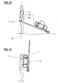
- branches of at least one of the parts 2, 3 can be, for example, broken, curved, etc. (cf. very schematic representations in Figures 9 and 10).
- the lower and upper parts 2 ', 3' also have an at least approximate shape of V, but the side members 5 ', 6' are of different construction.
- each branch of the V of a part for example 7 '
- the branch 8' joins the branch 7 'to be connected to it, then opens onto a section 8 ".
- This construction is part of the invention, but is less advantageous than the embodiment described above, due to a lower quality of rigidity and a risk of premature wear of the link (not referenced) to be provided in 4 ', this member being subjected to greater stresses (in particular torsion).
- the carriage 1 can finally be provided with a protection and additional comfort device 30 (see FIG. 1).
- This device 30 consists, according to the example, of a caster mounted madly on a shaft (not referenced). This shaft passes under the tubes 7 and 8, at the height of the cross member 14, and is connected to these elements 7, 8, 14 by the fixing means 41.
- This device 30 is of interest during the development in particularly uneven terrain. and / or sloping, or stair treads, since it then allows the absorption of strong inequalities, that is to say to prevent any collision of the chassis against the ground. On the other hand, when the ground is not or little damaged, this device will not come into contact with it.
- a material will preferably be chosen which will ideally combine mechanical qualities and lightness.
- a material will preferably be chosen which will ideally combine mechanical qualities and lightness.
- the carriage 1 can be towed while having your hands free, thanks to a fastening device 100 shown in Figure 12 (see also Figure 13).
- This device 100 essentially comprises a belt 101 provided, on the one hand, with two lateral straps 104 or suspenders for pulling the carriage 1, these straps comprising eyelets 105 and, on the other hand, with two adjustment and tightening means , according to the example a ventral loop 102 and a dorsal loop 103.
- This double loop system allows the user to adjust not only the belt to his size, but also and above all the straps 104 so that the centers of the eyelets 105 are located at least approximately in a plane P F (FIG. 13), this plane being formed by the axes of the right and left femurs. This adjustment is important for the reasons explained above (see passages preceding the presentation of the figures).
- the user After correct adjustment of the belt 101 around its size, the user connects the carriage 1 by its elements 9, 10 to the traction straps 104 by means of carabiners 106, at a height adapted to its size and which is best suited, that is to say so that the handles 11, 12 of the carriage 1 are close to his hands.
- This attachment device makes it possible to tow efficiently, and with maximum ease and ease, the carriage 1 provided with its load 16, the force components - located at the level of the pelvis of the user - not requesting the back of the latter. The user is free to move around but can, if necessary, take hold of the trolley or more simply place his hands on said handles.
- the belt 101 can be equipped with a pair of straps or suspenders 110 so as to form a harness for better comfort.
- These straps which can be padded in particular at the places where the shoulders pass, have a crosspiece 112 and each is provided, at the front, with tightening loops 111.
- the trolley is undeformable, without sacrificing its lightness. Also the user can load it easily and easily on his back, with the load 16 which is moored there, passing through his shoulders the straps 17 with which the latter is provided, when the surrounding conditions require it ( Figure 14) .
Landscapes
- Engineering & Computer Science (AREA)
- Chemical & Material Sciences (AREA)
- Combustion & Propulsion (AREA)
- Transportation (AREA)
- Mechanical Engineering (AREA)
- Portable Outdoor Equipment (AREA)
- Rehabilitation Tools (AREA)
- Handcart (AREA)
- Packaging Of Annular Or Rod-Shaped Articles, Wearing Apparel, Cassettes, Or The Like (AREA)
- Connection Of Plates (AREA)
- Dowels (AREA)
- Spinning Or Twisting Of Yarns (AREA)
- Orthopedics, Nursing, And Contraception (AREA)
Priority Applications (7)
| Application Number | Priority Date | Filing Date | Title |
|---|---|---|---|
| EP03405186A EP1459955B1 (de) | 2003-03-18 | 2003-03-18 | Transportvorrichtung für eine Last und passende Befestigungsvorrichtung |
| AT03405186T ATE344752T1 (de) | 2003-03-18 | 2003-03-18 | Transportvorrichtung für eine last und passende befestigungsvorrichtung |
| DE60309561T DE60309561T2 (de) | 2003-03-18 | 2003-03-18 | Transportvorrichtung für eine Last und passende Befestigungsvorrichtung |
| EP04405058A EP1459648A1 (de) | 2003-03-18 | 2004-01-29 | Einstellbarer Träger für ein Lasttransportgerät |
| AU2004200864A AU2004200864B2 (en) | 2003-03-18 | 2004-03-02 | Device for transporting a load and suitable attaching device |
| CA002460230A CA2460230C (en) | 2003-03-18 | 2004-03-08 | Device for transporting a load and suitable attaching device |
| US10/801,036 US7175188B2 (en) | 2003-03-18 | 2004-03-16 | Device for transporting a load and suitable attaching device |
Applications Claiming Priority (1)
| Application Number | Priority Date | Filing Date | Title |
|---|---|---|---|
| EP03405186A EP1459955B1 (de) | 2003-03-18 | 2003-03-18 | Transportvorrichtung für eine Last und passende Befestigungsvorrichtung |
Publications (2)
| Publication Number | Publication Date |
|---|---|
| EP1459955A1 true EP1459955A1 (de) | 2004-09-22 |
| EP1459955B1 EP1459955B1 (de) | 2006-11-08 |
Family
ID=32799189
Family Applications (1)
| Application Number | Title | Priority Date | Filing Date |
|---|---|---|---|
| EP03405186A Expired - Lifetime EP1459955B1 (de) | 2003-03-18 | 2003-03-18 | Transportvorrichtung für eine Last und passende Befestigungsvorrichtung |
Country Status (6)
| Country | Link |
|---|---|
| US (1) | US7175188B2 (de) |
| EP (1) | EP1459955B1 (de) |
| AT (1) | ATE344752T1 (de) |
| AU (1) | AU2004200864B2 (de) |
| CA (1) | CA2460230C (de) |
| DE (1) | DE60309561T2 (de) |
Cited By (2)
| Publication number | Priority date | Publication date | Assignee | Title |
|---|---|---|---|---|
| EP1489310A1 (de) * | 2003-06-19 | 2004-12-22 | François Joncourt | Vorrichtung zum Verbinden zweier Elemente, insbesondere rohrförmiger Elemente |
| CN106915368A (zh) * | 2015-12-27 | 2017-07-04 | 天津市鑫源泓达科技有限公司 | 一种新型货物运载小车 |
Families Citing this family (20)
| Publication number | Priority date | Publication date | Assignee | Title |
|---|---|---|---|---|
| US7422223B1 (en) * | 2004-09-15 | 2008-09-09 | David Joseph Silliman | Personal, lumbar friendly cargo carrier pack sled |
| US7484737B2 (en) * | 2005-04-16 | 2009-02-03 | Dale Jeffrey Satorius | Towable pack carrier |
| US7322584B1 (en) * | 2005-07-27 | 2008-01-29 | Parker George C | Pedestrian trailer |
| US20080174078A1 (en) * | 2007-01-18 | 2008-07-24 | Dooley Michael R | Pendent load-bearing device |
| US7611161B2 (en) * | 2007-01-22 | 2009-11-03 | Gross William L | Methods and apparatus for manually propelling a golf pull cart |
| US8002291B1 (en) * | 2007-02-06 | 2011-08-23 | Avelino A. Sandoval | Panel transport system and method |
| US8733766B2 (en) * | 2010-11-23 | 2014-05-27 | Timothy R. Nieman | Convertible conveyance method and apparatus |
| CN103373380A (zh) * | 2012-04-16 | 2013-10-30 | 邹芸天 | 拉车带 |
| DE102013104863B3 (de) * | 2013-05-10 | 2014-11-13 | Peter Krimmel | Tragesystem für schwere Lasten |
| US9409584B2 (en) | 2013-07-13 | 2016-08-09 | Thomas Joseph Jackson, JR. | Expedition carts and associated systems and methods |
| US9969412B2 (en) | 2013-07-13 | 2018-05-15 | Mcclellan Butte, Llc | Expedition carts and associated methods |
| US8979095B2 (en) * | 2013-08-02 | 2015-03-17 | Chase LEWIS | Wheeled travois |
| US10112638B2 (en) * | 2015-02-09 | 2018-10-30 | Kendall A. MORSE | Self-adjusting balanced multi-purpose transport carrier |
| JP6521438B2 (ja) * | 2015-03-27 | 2019-05-29 | 信夫 三宅 | 運搬用補助ベルト |
| US9758184B1 (en) * | 2015-04-21 | 2017-09-12 | Milton Vaverek | Three wheel cargo cart with lifting drawbar |
| US11261782B1 (en) * | 2020-04-24 | 2022-03-01 | Donald W. Alvis | Portable AC power pack |
| CN111559414A (zh) * | 2020-06-16 | 2020-08-21 | 中冶天工集团有限公司 | 一种石材搬运装置及其使用方法 |
| AT525120B1 (de) * | 2021-05-20 | 2025-01-15 | Mauritsch Friedrich | Mobile Einkaufstasche |
| US11945485B2 (en) * | 2021-07-02 | 2024-04-02 | The Nolan Company | Single wheeled knuckle carrier |
| US12296879B2 (en) * | 2021-12-27 | 2025-05-13 | John Jablonski | Military grade telescoping backpack extraction cart |
Citations (3)
| Publication number | Priority date | Publication date | Assignee | Title |
|---|---|---|---|---|
| US4664395A (en) * | 1985-10-03 | 1987-05-12 | Mccoy Melvin | Multi-purpose uniaxial litter enginery or M.U.L.E. |
| GB2206317A (en) * | 1987-05-12 | 1989-01-05 | Wheel Dev Ltd | Foldable wheelbarrow |
| FR2775878A1 (fr) * | 1998-03-10 | 1999-09-17 | Michel Besancon | Dispositif destine a aider les pietons a transporter les charges portees au moyen de courroies s'appuyant sur les epaules |
Family Cites Families (17)
| Publication number | Priority date | Publication date | Assignee | Title |
|---|---|---|---|---|
| US1623321A (en) * | 1924-09-15 | 1927-04-05 | Evander A Smith | Agricultural implement |
| DE723375C (de) | 1938-05-13 | 1942-08-03 | Franz Fuchs | Fuer verschiedene Zwecke verwendbare, zusammenlegbare, einraedrige Karre |
| US2593944A (en) * | 1946-05-09 | 1952-04-22 | Jr William M Walters | Utility garden tool |
| US2660446A (en) * | 1950-03-23 | 1953-11-24 | Edhardt Gosta Ewald | Folding wheelbarrow |
| US2672348A (en) * | 1952-05-31 | 1954-03-16 | Ralph W Scott | Collapsible hand truck |
| US3743312A (en) * | 1971-06-25 | 1973-07-03 | Raymond Lee Organization Inc | Combined wheel barrow and hand truck |
| CA1185937A (fr) | 1983-10-17 | 1985-04-23 | Jean-Claude Dorval | Support roulant pour sac a dos |
| US4564203A (en) * | 1984-11-23 | 1986-01-14 | Wilson Ronald E | Transport aid for A-frame stepladder |
| DE4202135C2 (de) | 1992-01-27 | 1994-11-24 | Knut Ewers | Lasttragegestell |
| DE4447319A1 (de) | 1994-12-31 | 1996-07-04 | Bernhard Hildebrandt | Tragegestell-Rucksack oder Tragegestell (Kraxe) mit erweiteter Handhabung |
| US5901968A (en) * | 1997-02-20 | 1999-05-11 | Niedersteiner; Anton M. | Pedestrian trailer system |
| DE29710339U1 (de) | 1997-06-13 | 1997-08-14 | Gebhardt, Fritz, 78073 Bad Dürrheim | Rucksack-Karren zerlegbar |
| US6139033A (en) * | 1998-11-20 | 2000-10-31 | Western; David Owen | Stable monowheel travois with counterweight feature |
| AU5353199A (en) | 1999-10-07 | 2001-04-12 | Chi Quang Wang | Back pack trolley |
| FR2817717B1 (fr) | 2000-12-07 | 2003-08-15 | Michel Besancon | Dispositif d'aide au portage et a la traction des charges dorsales et des skis |
| US6631777B1 (en) * | 2002-06-17 | 2003-10-14 | Allister Wade Thompson | Transport vehicle for skaters and skiers |
| JP2004200864A (ja) * | 2002-12-17 | 2004-07-15 | Nissan Motor Co Ltd | 車両周囲監視装置及び車両周囲監視方法 |
-
2003
- 2003-03-18 EP EP03405186A patent/EP1459955B1/de not_active Expired - Lifetime
- 2003-03-18 DE DE60309561T patent/DE60309561T2/de not_active Expired - Lifetime
- 2003-03-18 AT AT03405186T patent/ATE344752T1/de not_active IP Right Cessation
-
2004
- 2004-03-02 AU AU2004200864A patent/AU2004200864B2/en not_active Expired - Fee Related
- 2004-03-08 CA CA002460230A patent/CA2460230C/en not_active Expired - Fee Related
- 2004-03-16 US US10/801,036 patent/US7175188B2/en not_active Expired - Fee Related
Patent Citations (3)
| Publication number | Priority date | Publication date | Assignee | Title |
|---|---|---|---|---|
| US4664395A (en) * | 1985-10-03 | 1987-05-12 | Mccoy Melvin | Multi-purpose uniaxial litter enginery or M.U.L.E. |
| GB2206317A (en) * | 1987-05-12 | 1989-01-05 | Wheel Dev Ltd | Foldable wheelbarrow |
| FR2775878A1 (fr) * | 1998-03-10 | 1999-09-17 | Michel Besancon | Dispositif destine a aider les pietons a transporter les charges portees au moyen de courroies s'appuyant sur les epaules |
Cited By (2)
| Publication number | Priority date | Publication date | Assignee | Title |
|---|---|---|---|---|
| EP1489310A1 (de) * | 2003-06-19 | 2004-12-22 | François Joncourt | Vorrichtung zum Verbinden zweier Elemente, insbesondere rohrförmiger Elemente |
| CN106915368A (zh) * | 2015-12-27 | 2017-07-04 | 天津市鑫源泓达科技有限公司 | 一种新型货物运载小车 |
Also Published As
| Publication number | Publication date |
|---|---|
| US20040183263A1 (en) | 2004-09-23 |
| AU2004200864B2 (en) | 2006-05-11 |
| CA2460230C (en) | 2009-01-27 |
| AU2004200864A1 (en) | 2004-10-07 |
| ATE344752T1 (de) | 2006-11-15 |
| US7175188B2 (en) | 2007-02-13 |
| DE60309561T2 (de) | 2007-10-11 |
| EP1459955B1 (de) | 2006-11-08 |
| CA2460230A1 (en) | 2004-09-18 |
| DE60309561D1 (de) | 2006-12-21 |
Similar Documents
| Publication | Publication Date | Title |
|---|---|---|
| EP1459955B1 (de) | Transportvorrichtung für eine Last und passende Befestigungsvorrichtung | |
| FR2608058A1 (fr) | Mallette pour le rangement d'un equipement de golf, convertible en un chariot de golf | |
| FR2974279A1 (fr) | Dispositif de bagage combine a un moyen de transport individuel | |
| EP3980144B1 (de) | Individuelles fortbewegungsmittel, bestehend aus einem paar motorisierter rollschuhe | |
| EP0940160B1 (de) | Schneesportgerät | |
| FR2993237A1 (fr) | Moyen de pliage verrouillage adapte a un vehicule terrestre ayant des elements de structure tubulaire | |
| EP3042642B1 (de) | Transportvorrichtung für eine person | |
| EP1909931B1 (de) | Langlaufski mit rädern | |
| EP3581474B1 (de) | Skimaterial-transportvorrichtung für fahrrad | |
| FR2958176A1 (fr) | Dispositif de freinage par commande manuelle, agissant simultanement sur l'ensemble des roulettes, pour patin a roulettes en ligne | |
| FR2903582A1 (fr) | Dispositif pour transporter une charge soit par roulement ou soit par partage sur le dos. | |
| EP1688335A1 (de) | Cart in particular for hiker | |
| FR2771645A1 (fr) | Dispositif de deplacement sur neige | |
| FR2556228A1 (fr) | Patins a roulettes, dont les roues ont une inclinaison variable par rapport au sol | |
| FR2915728A1 (fr) | Trotinette | |
| FR2901224A1 (fr) | Dispositif de transport de charges. | |
| CH703088A2 (fr) | Dispositif de transport de charges à usage multiple. | |
| FR3118399A1 (fr) | Accessoire pliable et kit monte-escaliers pour valise, methode de gravissement ou de descente d’escaliers avec une valise | |
| FR2974556A3 (fr) | Chariot pour le transport des bagages en randonnée. polyvalent, il permet le roulage sur une ou deux roues, le portage. modulaire, c'est trois utilisations possibles d'un même accessoire en fonction de la configuration du terrain. | |
| WO2026033249A1 (fr) | Mini-skate pliable « low gravity » a freinage automatique dont les axes de conduite sont logés dans des amortisseurs en elastomère | |
| FR2858288A1 (fr) | Chariot pour randonneur | |
| FR2863466A1 (fr) | Dispositif pour le transport d'un enfant fixable sur une valise. | |
| FR2931779A1 (fr) | Dispositif roulant pour transporter au moins une personne. | |
| FR2754721A1 (fr) | Echasses a cale-pied | |
| FR2993235A3 (fr) | Scooter equipe d'un sac a dos detachable |
Legal Events
| Date | Code | Title | Description |
|---|---|---|---|
| PUAI | Public reference made under article 153(3) epc to a published international application that has entered the european phase |
Free format text: ORIGINAL CODE: 0009012 |
|
| 17P | Request for examination filed |
Effective date: 20031128 |
|
| AK | Designated contracting states |
Kind code of ref document: A1 Designated state(s): AT BE BG CH CY CZ DE DK EE ES FI FR GB GR HU IE IT LI LU MC NL PT RO SE SI SK TR |
|
| AX | Request for extension of the european patent |
Extension state: AL LT LV MK RO |
|
| AKX | Designation fees paid |
Designated state(s): AT BE BG CH CY CZ DE DK EE ES FI FR GB GR HU IE IT LI LU MC NL PT RO SE SI SK TR |
|
| GRAP | Despatch of communication of intention to grant a patent |
Free format text: ORIGINAL CODE: EPIDOSNIGR1 |
|
| GRAS | Grant fee paid |
Free format text: ORIGINAL CODE: EPIDOSNIGR3 |
|
| GRAA | (expected) grant |
Free format text: ORIGINAL CODE: 0009210 |
|
| AK | Designated contracting states |
Kind code of ref document: B1 Designated state(s): AT BE BG CH CY CZ DE DK EE ES FI FR GB GR HU IE IT LI LU MC NL PT RO SE SI SK TR |
|
| PG25 | Lapsed in a contracting state [announced via postgrant information from national office to epo] |
Ref country code: IT Free format text: LAPSE BECAUSE OF FAILURE TO SUBMIT A TRANSLATION OF THE DESCRIPTION OR TO PAY THE FEE WITHIN THE PRESCRIBED TIME-LIMIT;WARNING: LAPSES OF ITALIAN PATENTS WITH EFFECTIVE DATE BEFORE 2007 MAY HAVE OCCURRED AT ANY TIME BEFORE 2007. THE CORRECT EFFECTIVE DATE MAY BE DIFFERENT FROM THE ONE RECORDED. Effective date: 20061108 Ref country code: IE Free format text: LAPSE BECAUSE OF FAILURE TO SUBMIT A TRANSLATION OF THE DESCRIPTION OR TO PAY THE FEE WITHIN THE PRESCRIBED TIME-LIMIT Effective date: 20061108 Ref country code: SI Free format text: LAPSE BECAUSE OF FAILURE TO SUBMIT A TRANSLATION OF THE DESCRIPTION OR TO PAY THE FEE WITHIN THE PRESCRIBED TIME-LIMIT Effective date: 20061108 Ref country code: AT Free format text: LAPSE BECAUSE OF FAILURE TO SUBMIT A TRANSLATION OF THE DESCRIPTION OR TO PAY THE FEE WITHIN THE PRESCRIBED TIME-LIMIT Effective date: 20061108 Ref country code: NL Free format text: LAPSE BECAUSE OF FAILURE TO SUBMIT A TRANSLATION OF THE DESCRIPTION OR TO PAY THE FEE WITHIN THE PRESCRIBED TIME-LIMIT Effective date: 20061108 Ref country code: RO Free format text: LAPSE BECAUSE OF FAILURE TO SUBMIT A TRANSLATION OF THE DESCRIPTION OR TO PAY THE FEE WITHIN THE PRESCRIBED TIME-LIMIT Effective date: 20061108 Ref country code: CZ Free format text: LAPSE BECAUSE OF FAILURE TO SUBMIT A TRANSLATION OF THE DESCRIPTION OR TO PAY THE FEE WITHIN THE PRESCRIBED TIME-LIMIT Effective date: 20061108 Ref country code: FI Free format text: LAPSE BECAUSE OF FAILURE TO SUBMIT A TRANSLATION OF THE DESCRIPTION OR TO PAY THE FEE WITHIN THE PRESCRIBED TIME-LIMIT Effective date: 20061108 Ref country code: SK Free format text: LAPSE BECAUSE OF FAILURE TO SUBMIT A TRANSLATION OF THE DESCRIPTION OR TO PAY THE FEE WITHIN THE PRESCRIBED TIME-LIMIT Effective date: 20061108 |
|
| REG | Reference to a national code |
Ref country code: GB Ref legal event code: FG4D Free format text: NOT ENGLISH |
|
| REG | Reference to a national code |
Ref country code: CH Ref legal event code: EP |
|
| REG | Reference to a national code |
Ref country code: IE Ref legal event code: FG4D Free format text: LANGUAGE OF EP DOCUMENT: FRENCH |
|
| REF | Corresponds to: |
Ref document number: 60309561 Country of ref document: DE Date of ref document: 20061221 Kind code of ref document: P |
|
| REG | Reference to a national code |
Ref country code: CH Ref legal event code: NV Representative=s name: AMMANN PATENTANWAELTE AG BERN |
|
| PG25 | Lapsed in a contracting state [announced via postgrant information from national office to epo] |
Ref country code: BG Free format text: LAPSE BECAUSE OF FAILURE TO SUBMIT A TRANSLATION OF THE DESCRIPTION OR TO PAY THE FEE WITHIN THE PRESCRIBED TIME-LIMIT Effective date: 20070208 Ref country code: SE Free format text: LAPSE BECAUSE OF FAILURE TO SUBMIT A TRANSLATION OF THE DESCRIPTION OR TO PAY THE FEE WITHIN THE PRESCRIBED TIME-LIMIT Effective date: 20070208 Ref country code: DK Free format text: LAPSE BECAUSE OF FAILURE TO SUBMIT A TRANSLATION OF THE DESCRIPTION OR TO PAY THE FEE WITHIN THE PRESCRIBED TIME-LIMIT Effective date: 20070208 |
|
| PG25 | Lapsed in a contracting state [announced via postgrant information from national office to epo] |
Ref country code: ES Free format text: LAPSE BECAUSE OF FAILURE TO SUBMIT A TRANSLATION OF THE DESCRIPTION OR TO PAY THE FEE WITHIN THE PRESCRIBED TIME-LIMIT Effective date: 20070219 |
|
| PG25 | Lapsed in a contracting state [announced via postgrant information from national office to epo] |
Ref country code: PT Free format text: LAPSE BECAUSE OF FAILURE TO SUBMIT A TRANSLATION OF THE DESCRIPTION OR TO PAY THE FEE WITHIN THE PRESCRIBED TIME-LIMIT Effective date: 20070409 |
|
| NLV1 | Nl: lapsed or annulled due to failure to fulfill the requirements of art. 29p and 29m of the patents act | ||
| GBV | Gb: ep patent (uk) treated as always having been void in accordance with gb section 77(7)/1977 [no translation filed] |
Effective date: 20061108 |
|
| REG | Reference to a national code |
Ref country code: IE Ref legal event code: FD4D |
|
| PLBE | No opposition filed within time limit |
Free format text: ORIGINAL CODE: 0009261 |
|
| STAA | Information on the status of an ep patent application or granted ep patent |
Free format text: STATUS: NO OPPOSITION FILED WITHIN TIME LIMIT |
|
| 26N | No opposition filed |
Effective date: 20070809 |
|
| PG25 | Lapsed in a contracting state [announced via postgrant information from national office to epo] |
Ref country code: GB Free format text: LAPSE BECAUSE OF FAILURE TO SUBMIT A TRANSLATION OF THE DESCRIPTION OR TO PAY THE FEE WITHIN THE PRESCRIBED TIME-LIMIT Effective date: 20061108 |
|
| BERE | Be: lapsed |
Owner name: JONCOURT, FRANCOIS Effective date: 20070331 |
|
| PG25 | Lapsed in a contracting state [announced via postgrant information from national office to epo] |
Ref country code: BE Free format text: LAPSE BECAUSE OF NON-PAYMENT OF DUE FEES Effective date: 20070331 |
|
| PG25 | Lapsed in a contracting state [announced via postgrant information from national office to epo] |
Ref country code: MC Free format text: LAPSE BECAUSE OF NON-PAYMENT OF DUE FEES Effective date: 20070331 |
|
| PG25 | Lapsed in a contracting state [announced via postgrant information from national office to epo] |
Ref country code: GR Free format text: LAPSE BECAUSE OF FAILURE TO SUBMIT A TRANSLATION OF THE DESCRIPTION OR TO PAY THE FEE WITHIN THE PRESCRIBED TIME-LIMIT Effective date: 20070209 |
|
| PG25 | Lapsed in a contracting state [announced via postgrant information from national office to epo] |
Ref country code: EE Free format text: LAPSE BECAUSE OF FAILURE TO SUBMIT A TRANSLATION OF THE DESCRIPTION OR TO PAY THE FEE WITHIN THE PRESCRIBED TIME-LIMIT Effective date: 20061108 |
|
| PG25 | Lapsed in a contracting state [announced via postgrant information from national office to epo] |
Ref country code: CY Free format text: LAPSE BECAUSE OF FAILURE TO SUBMIT A TRANSLATION OF THE DESCRIPTION OR TO PAY THE FEE WITHIN THE PRESCRIBED TIME-LIMIT Effective date: 20061108 Ref country code: LU Free format text: LAPSE BECAUSE OF NON-PAYMENT OF DUE FEES Effective date: 20070318 |
|
| PG25 | Lapsed in a contracting state [announced via postgrant information from national office to epo] |
Ref country code: TR Free format text: LAPSE BECAUSE OF FAILURE TO SUBMIT A TRANSLATION OF THE DESCRIPTION OR TO PAY THE FEE WITHIN THE PRESCRIBED TIME-LIMIT Effective date: 20061108 Ref country code: HU Free format text: LAPSE BECAUSE OF FAILURE TO SUBMIT A TRANSLATION OF THE DESCRIPTION OR TO PAY THE FEE WITHIN THE PRESCRIBED TIME-LIMIT Effective date: 20070509 |
|
| REG | Reference to a national code |
Ref country code: FR Ref legal event code: PLFP Year of fee payment: 13 |
|
| PGFP | Annual fee paid to national office [announced via postgrant information from national office to epo] |
Ref country code: CH Payment date: 20150326 Year of fee payment: 13 Ref country code: DE Payment date: 20150320 Year of fee payment: 13 |
|
| PGFP | Annual fee paid to national office [announced via postgrant information from national office to epo] |
Ref country code: FR Payment date: 20150319 Year of fee payment: 13 |
|
| REG | Reference to a national code |
Ref country code: DE Ref legal event code: R119 Ref document number: 60309561 Country of ref document: DE |
|
| REG | Reference to a national code |
Ref country code: CH Ref legal event code: PL |
|
| REG | Reference to a national code |
Ref country code: FR Ref legal event code: ST Effective date: 20161130 |
|
| PG25 | Lapsed in a contracting state [announced via postgrant information from national office to epo] |
Ref country code: LI Free format text: LAPSE BECAUSE OF NON-PAYMENT OF DUE FEES Effective date: 20160331 Ref country code: CH Free format text: LAPSE BECAUSE OF NON-PAYMENT OF DUE FEES Effective date: 20160331 Ref country code: DE Free format text: LAPSE BECAUSE OF NON-PAYMENT OF DUE FEES Effective date: 20161001 Ref country code: FR Free format text: LAPSE BECAUSE OF NON-PAYMENT OF DUE FEES Effective date: 20160331 |