EP1459961B2 - Véhicule à moteur avec colonne de direction mécanique et un système pour la détection de la déviation par rapport à une voie de circulation ou pour la détection de l'occupation d'une voie de circulation voisine - Google Patents
Véhicule à moteur avec colonne de direction mécanique et un système pour la détection de la déviation par rapport à une voie de circulation ou pour la détection de l'occupation d'une voie de circulation voisine Download PDFInfo
- Publication number
- EP1459961B2 EP1459961B2 EP20040003212 EP04003212A EP1459961B2 EP 1459961 B2 EP1459961 B2 EP 1459961B2 EP 20040003212 EP20040003212 EP 20040003212 EP 04003212 A EP04003212 A EP 04003212A EP 1459961 B2 EP1459961 B2 EP 1459961B2
- Authority
- EP
- European Patent Office
- Prior art keywords
- motor vehicle
- vehicle according
- electric motor
- torque
- steering column
- Prior art date
- Legal status (The legal status is an assumption and is not a legal conclusion. Google has not performed a legal analysis and makes no representation as to the accuracy of the status listed.)
- Expired - Lifetime
Links
Images


Classifications
-
- F—MECHANICAL ENGINEERING; LIGHTING; HEATING; WEAPONS; BLASTING
- F16—ENGINEERING ELEMENTS AND UNITS; GENERAL MEASURES FOR PRODUCING AND MAINTAINING EFFECTIVE FUNCTIONING OF MACHINES OR INSTALLATIONS; THERMAL INSULATION IN GENERAL
- F16D—COUPLINGS FOR TRANSMITTING ROTATION; CLUTCHES; BRAKES
- F16D41/00—Freewheels or freewheel clutches
- F16D41/06—Freewheels or freewheel clutches with intermediate wedging coupling members between an inner and an outer surface
- F16D41/063—Freewheels or freewheel clutches with intermediate wedging coupling members between an inner and an outer surface the intermediate members wedging by moving along the inner and the outer surface without pivoting or rolling, e.g. sliding wedges
-
- B—PERFORMING OPERATIONS; TRANSPORTING
- B62—LAND VEHICLES FOR TRAVELLING OTHERWISE THAN ON RAILS
- B62D—MOTOR VEHICLES; TRAILERS
- B62D15/00—Steering not otherwise provided for
- B62D15/02—Steering position indicators ; Steering position determination; Steering aids
- B62D15/029—Steering assistants using warnings or proposing actions to the driver without influencing the steering system
-
- F—MECHANICAL ENGINEERING; LIGHTING; HEATING; WEAPONS; BLASTING
- F16—ENGINEERING ELEMENTS AND UNITS; GENERAL MEASURES FOR PRODUCING AND MAINTAINING EFFECTIVE FUNCTIONING OF MACHINES OR INSTALLATIONS; THERMAL INSULATION IN GENERAL
- F16D—COUPLINGS FOR TRANSMITTING ROTATION; CLUTCHES; BRAKES
- F16D43/00—Automatic clutches
- F16D43/02—Automatic clutches actuated entirely mechanically
- F16D43/04—Automatic clutches actuated entirely mechanically controlled by angular speed
-
- B—PERFORMING OPERATIONS; TRANSPORTING
- B60—VEHICLES IN GENERAL
- B60T—VEHICLE BRAKE CONTROL SYSTEMS OR PARTS THEREOF; BRAKE CONTROL SYSTEMS OR PARTS THEREOF, IN GENERAL; ARRANGEMENT OF BRAKING ELEMENTS ON VEHICLES IN GENERAL; PORTABLE DEVICES FOR PREVENTING UNWANTED MOVEMENT OF VEHICLES; VEHICLE MODIFICATIONS TO FACILITATE COOLING OF BRAKES
- B60T2201/00—Particular use of vehicle brake systems; Special systems using also the brakes; Special software modules within the brake system controller
- B60T2201/08—Lane monitoring; Lane Keeping Systems
- B60T2201/082—Lane monitoring; Lane Keeping Systems using alarm actuation
Definitions
- Such a motor vehicle with a driver assistance system which makes it possible to detect the lane departure and process the resulting information, is known as a so-called LDW (Lane Departure Warning) system.
- LDW Lane Departure Warning
- the information of the driver about the respective system detection result takes place - if the driver is to be informed - sometimes via a haptic, detectable via the steering wheel signal.
- the steering wheel vibrates, for which it is assigned a suitable vibration device, which is controlled when necessary.
- the steering wheel is preferably used for this purpose because very short reaction times can be achieved on the steering wheel because of the stimulus-reaction compatibility. In addition, in a warning on the steering wheel only informed the driver and the passengers are not disturbed.
- EP 0 640 903 B1 discloses a lane keeping system, by means of which - if necessary without the assistance of the driver - the vehicle is held in the middle of the lane. For this purpose, an additional torque is introduced into the steering system, depending on the signals of a track detection system, so that a steering preload is exerted on removal of the lane center. The driver is thereby given the feeling of driving in a kind of tub. If too close to the lane boundary another torque can be generated, which triggers a vibration of the steering wheel and thus achieves a warning effect. If the system is deactivated, it can be disengaged by a clutch.
- the device itself should be designed in this way and / or the given torque should be such that the steering wheel is rotatable in the opposite direction by the driver despite the device in operation and / or given torque.
- the device thus does not block the steering wheel movement in a direction opposite to the applied torque or the resulting steering wheel rotation opposite direction. So it is always possible that a driver who z. B. consciously wants to drive over the middle lane, for example, in an overtaking process, although receives a short-term direction-selective information when the deviation detection system detects a sufficient approach to the center line, but he can overturn this rotational movement readily to continue the lane change can.
- the engagement means expediently comprises at least one gearwheel which can be driven via the electric motor and which meshes with a toothing provided on the steering column for the purpose of applying the torque. This gear is then brought into meshing engagement with the steering column-side toothing, if a detection result according to a torque must be given, otherwise the driven via the electric motor gear is disengaged from the steering column toothing.
- two gears are provided on a rocker movable via the shaft of the electric motor, both of which mesh with a pinion arranged on the shaft and between the two toothed wheels.
- the engagement means comprises at least one via the electric motor driven gear and an attacking on this and the application of torque on the steering column chain or timing belt or V-belt, wherein the engagement means is suitably designed such that the chain or the Timing belt or V-belt is released in a rest position of the column-side toothing and engages only during operation of the electric motor of this. That is, the chain / timing belt / V-belt is tensioned only when the electric motor is in operation and applied to the steering column, which otherwise can rotate freely.
- a further movable over the shaft of the electric motor rocker is provided in a development of the inventive concept, are arranged on the two arranged on the shaft, located between them pinion movable gears.
- a system 8 for example, for detecting a deviation of the traffic lane of the motor vehicle 1 from an excellent lane of the roadway.
- this device comprises a camera 9, which looks out to the front of the windshield and picks up a vehicle apron. you connected downstream is a Schmausnoi- and control device 10, which is designed such that any leading to a dangerous situation approach to a lane boundary marking and the like, ie a dangerous leaving the excellent lane, is detected.
- a comparable detection signal could come from a lane change assistance system, which detects a busy adjacent lane when changing lanes. This, a danger situation or an approaching dangerous situation indicating detection signal is given to the controller 6.
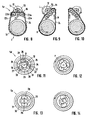
- Fig. 7 shows the operation when the electric motor is energized according to different poles.
- the rocker rotates at the direction of rotation by an angle of more than 180 ° and must be arranged in a corresponding space.
- FIGS. 13 and 14 show a further embodiment of a device 5e.
- two drivers 26 are provided, both as the FIGS. 13 and 14 show over the molding 25 depending on the direction of rotation to the left or right in engagement with the internal teeth 30 of the coupling ring 31 can be brought.
- Fig. 15 shows a sectional view through such an arrangement 5e in the form of a schematic diagram. Shown there is the electric motor 13 and the molded part 25, which are the driver 26, which are arranged correspondingly pivotable on suitable drive plates 32, are attached.
- the coupling ring 31 with its internal toothing 30 is closed capsule-like at one end and shows an output shaft 33, on which also the belt coupling can be provided to the steering column.
- Fig. 18 finally shows a further embodiment of a device 5g.
- the drivers 26 are mounted longitudinally displaceable in a corresponding holder 34. If the molded part 25 is rotated, the drivers 26 are longitudinally displaced and brought outwardly into engagement with the internal toothing 30 of the coupling ring 31. Rotates the molding 25 on, depending on the direction of rotation of the angular momentum issued and placed on the belt coupling on the steering column.
Landscapes
- Engineering & Computer Science (AREA)
- General Engineering & Computer Science (AREA)
- Mechanical Engineering (AREA)
- Chemical & Material Sciences (AREA)
- Combustion & Propulsion (AREA)
- Transportation (AREA)
- Power Steering Mechanism (AREA)
- Steering Control In Accordance With Driving Conditions (AREA)
Claims (18)
- Véhicule automobile équipé d'un système de direction comprenant une colonne de direction (3) incluant le volant de direction (4) et équipé d'un système (8) servant à détecter toute déviation de la voie de circulation par le véhicule automobile par rapport à la voie de circulation enregistrée de la chaussée,
sachant qu'un dispositif (5, 5a, ..., 5h) est prévu pour fournir directement ou indirectement un couple de rotation perceptible de manière haptique par l'intermédiaire du volant de direction (4), servant à avertir le conducteur, n'intervenant pas dans le fonctionnement de direction à proprement parler selon une déviation de direction détectée par le système de détection de déviation (8), sachant que le dispositif (5, 5a, ..., 5h) servant à fournir le couple de rotation vient en prise au niveau de la colonne de direction (3), délivre à cette dernière le couple de rotation et comprend un moteur électrique (13) fonctionnant pour fournir le couple de rotation,
caractérisé en ce
que le couple de rotation à fournir est appliqué de manière sélective en direction et de manière impulsionnelle, et en ce qu'un moyen d'engrènement mécanique est associé au moteur électrique (13), ledit moyen d'engrènement étant couplé à la colonne de direction (3) grâce au fonctionnement du moteur électrique (13) ou permettant de coupler le moteur électrique (13), par son fonctionnement, à la colonne de direction (3). - Véhicule automobile selon la revendication 1,
caractérisé en ce
que le dispositif (5, 5a, ..., 5h) est conçu de telle manière et/ou que le couple de rotation fourni présente des mesures telles que le volant de direction (4) peut être tourné par le conducteur dans le sens opposé en dépit du dispositif (5, 5a, ..., 5h) en fonctionnement et/ou en dépit du couple de rotation fourni. - Véhicule automobile selon la revendication 1 ou 2,
caractérisé en ce
que le dispositif (5, 5a, ..., 5h) vient en prise au niveau du volant de direction (3) ou est relié à ce dernier de manière à transmettre le couple uniquement pendant la période au cours de laquelle le couple de rotation est à fournir. - Véhicule automobile selon l'une quelconque des revendications précédentes,
caractérisé en ce
que sont prévus des moyens (17, 29) servant à rappeler dans une position de repos le moyen d'engrènement mécanique, lorsque le moteur électrique (13) ne fonctionne plus. - Véhicule automobile selon la revendication 4,
caractérisé en ce que les moyens comprennent un ou plusieurs ressorts de rappel (17, 29), lesquels amènent le moyen d'engrènement dans la position de repos. - Véhicule automobile selon l'une quelconque des revendications précédentes,
caractérisé en ce
qu'au moins une roue dentée (15a, 15b, 20) pouvant être entraînée par l'intermédiaire du moteur électrique (13) comprend des moyens d'engrènement, ladite roue dentée venant en prise avec une denture (18) prévue au niveau de la colonne de direction (3) afin de délivrer le couple de rotation. - Véhicule automobile selon la revendication 6,
caractérisé en ce
que sont prévues deux roues dentées (15a, 15b), lesquelles sont disposées sur une bascule (16) pouvant être déplacée sur l'arbre (12) du moteur électrique (13) et qui viennent en prise avec un pignon (14) disposé sur l'arbre (12) et entre les deux roues dentées (15a, 15b). - Véhicule automobile selon la revendication 7,
caractérisé en ce
que les moyens de rappel, en particulier les ressorts de rappel (17), viennent en prise au niveau de la bascule (16). - Véhicule automobile selon la revendication 6,
caractérisé en ce
qu'est prévu un bras de pivotement (19), qui peut être déplacé sur l'arbre (12) du moteur électrique (13) et au niveau duquel est disposée la roue dentée (20) venant en prise avec un pignon (14) disposé au niveau de l'arbre (12). - Véhicule automobile selon l'une quelconque des revendications 1 à 5,
caractérisé en ce
que le moyen d'engrènement comprend au moins une roue dentée (23a, 23b) pouvant être entraînée par l'intermédiaire du moteur électrique (13) et une chaîne (24) ou une courroie dentée ou une courroie trapézoïdale venant en prise au niveau de la roue dentée et également au niveau de la colonne de direction (3) afin de fournir le couple de rotation. - Véhicule automobile selon la revendication 10,
caractérisé en ce
que le moyen d'engrènement est réalisé de telle manière que la chaîne (24) ou la courroie dentée ou la courroie trapézoïdale est détachée de la denture (18) côté colonne dans la position de repos et vient en prise au niveau de ladite denture uniquement dès que le moteur électrique (13) fonctionne. - Véhicule automobile selon la revendication 11,
caractérisé en ce
qu'est prévue une bascule (16), qui peut être déplacée sur l'arbre (12) du moteur électrique (13) et au niveau de laquelle sont disposées deux roues dentées disposées au niveau de l'arbre (12), pouvant être déplacées entre le pignon (21) se trouvant entre elles. - Véhicule automobile selon l'une quelconque des revendications 1 à 5,
caractérisé en ce
que le moyen d'engrènement présente une bague de couplage (31) cinétiquement couplée à la colonne de direction (3), présentant une denture intérieure (30), avec laquelle, lorsque le moteur électrique (13) est en fonctionnement, un ou plusieurs éléments entraîneurs (26), présentant une denture extérieure (28), peuvent être amenés en prise, lesdits éléments entraîneurs étant entraînés directement ou indirectement par le moteur électrique (13). - Véhicule automobile selon la revendication 13,
caractérisé en ce
que plusieurs entraîneurs (26) sont disposés autour d'une pièce moulée (25) disposée au niveau de l'arbre de moteur (12) de telle manière qu'ils peuvent être déplacés en prise avec la denture intérieure (30) lors d'une rotation de la pièce moulée (25) vers l'extérieur. - Véhicule automobile selon la revendication 14,
caractérisé en ce
que l'entraîneur ou chaque entraîneur (26) est monté de manière rotative ou déplacé longitudinalement par coulissement autour d'un axe de rotation (27). - Véhicule automobile selon l'une quelconque des revendications 13 à 15,
caractérisé en ce
que chaque entraîneur (26) est monté dans le sens opposé à une force de rappel. - Véhicule automobile selon la revendication 16,
caractérisé en ce
que chaque entraîneur (26) est couplé à un autre entraîneur (26) par l'intermédiaire d'un élément formant ressort (29) de rappel. - Véhicule automobile selon l'une quelconque des revendications 13 à 17,
caractérisé en ce
que la bague de couplage (31) est couplée à la colonne de direction cinétiquement et de manière durable par l'intermédiaire d'une courroie, en particulier par l'intermédiaire d'une courroie dentée.
Applications Claiming Priority (2)
| Application Number | Priority Date | Filing Date | Title |
|---|---|---|---|
| DE10306100 | 2003-02-14 | ||
| DE2003106100 DE10306100C5 (de) | 2003-02-14 | 2003-02-14 | Kraftfahrzeug mit einem Lenksystem umfassend eine mechanische Lenksäule samt Lenkrad sowie einem System zur Erfassung einer Abweichung der Fahrspur des Kraftfahrzeugs von einer ausgezeichneten Fahrspur der Fahrbahn oder zur Erfassung einer Belegung einer Nachbarspur |
Publications (4)
| Publication Number | Publication Date |
|---|---|
| EP1459961A2 EP1459961A2 (fr) | 2004-09-22 |
| EP1459961A3 EP1459961A3 (fr) | 2005-01-19 |
| EP1459961B1 EP1459961B1 (fr) | 2006-09-13 |
| EP1459961B2 true EP1459961B2 (fr) | 2014-11-12 |
Family
ID=32797392
Family Applications (1)
| Application Number | Title | Priority Date | Filing Date |
|---|---|---|---|
| EP20040003212 Expired - Lifetime EP1459961B2 (fr) | 2003-02-14 | 2004-02-13 | Véhicule à moteur avec colonne de direction mécanique et un système pour la détection de la déviation par rapport à une voie de circulation ou pour la détection de l'occupation d'une voie de circulation voisine |
Country Status (2)
| Country | Link |
|---|---|
| EP (1) | EP1459961B2 (fr) |
| DE (2) | DE10306100C5 (fr) |
Families Citing this family (11)
| Publication number | Priority date | Publication date | Assignee | Title |
|---|---|---|---|---|
| DE102004062820A1 (de) * | 2004-12-27 | 2006-07-06 | Robert Bosch Gmbh | Fahrzustandsüberwachungseinrichtung für ein Kraftfahrzeug |
| DE102005036219B4 (de) * | 2005-08-02 | 2021-06-17 | Bayerische Motoren Werke Aktiengesellschaft | Fahrerassistenzsystem |
| DE102006043122B4 (de) * | 2006-09-11 | 2012-01-12 | Deutsches Zentrum für Luft- und Raumfahrt e.V. | Spurhalteassistent und Verfahren zur Spurhaltung eines Fahrzeugs |
| DE102008005793A1 (de) * | 2008-01-23 | 2009-07-30 | Thyssenkrupp Presta Ag | Lenkungsanordnung für ein Fahrzeug |
| DE102008011621B3 (de) | 2008-02-28 | 2009-08-13 | Thyssenkrupp Presta Ag | Lenkungsanordnung für ein Fahrzeug |
| WO2013026616A1 (fr) * | 2011-08-22 | 2013-02-28 | Bayerische Motoren Werke Aktiengesellschaft | Système d'aide à la conduite destiné à un véhicule non guidé sur rails |
| DE102012222245B4 (de) * | 2012-12-04 | 2021-12-09 | Bayerische Motoren Werke Aktiengesellschaft | Verfahren zur Abgabe einer Lenkempfehlung |
| US10773642B2 (en) | 2013-11-06 | 2020-09-15 | Frazier Cunningham, III | Vehicle driver nudge system |
| DE102015214351A1 (de) | 2015-07-29 | 2017-02-02 | Continental Automotive Gmbh | Verfahren zum Betrieb eines Kraftfahrzeugs mit einer haptischen Signalisierung an den Fahrer |
| US11124220B2 (en) | 2017-12-19 | 2021-09-21 | Mando Corporation | Steer-by-wire type steering apparatus |
| DE102018127306A1 (de) * | 2018-10-31 | 2020-04-30 | Trw Automotive Gmbh | Verfahren zur Unterstützung eines Fahrers eines Fahrzeugs, Sicherheitsvorrichtung für ein Fahrzeug und Fahrzeug |
Family Cites Families (13)
| Publication number | Priority date | Publication date | Assignee | Title |
|---|---|---|---|---|
| US1686020A (en) * | 1926-03-06 | 1928-10-02 | Bethlehem Steel Corp | Gearing mechanism |
| JPS6133367A (ja) * | 1984-07-25 | 1986-02-17 | Aisin Seiki Co Ltd | 電動パワ−ステアリングの動力伝達装置 |
| US4726437A (en) * | 1986-05-05 | 1988-02-23 | Peter Norton | Servo steering system |
| DE3822193A1 (de) * | 1988-07-01 | 1990-01-04 | Bosch Gmbh Robert | Verfahren und vorrichtung zur haptischen anzeige der abstandswarnung im kraftfahrzeug |
| JPH02189270A (ja) * | 1989-01-19 | 1990-07-25 | Atsugi Unisia Corp | 電動パワーステアリング装置 |
| GB9317983D0 (en) * | 1993-08-28 | 1993-10-13 | Lucas Ind Plc | A driver assistance system for a vehicle |
| JP3516315B2 (ja) * | 1995-07-05 | 2004-04-05 | 本田技研工業株式会社 | 電動パワーステアリング装置 |
| JP3647538B2 (ja) * | 1996-02-12 | 2005-05-11 | 本田技研工業株式会社 | 車両操舵装置 |
| DE19837340B4 (de) * | 1998-08-18 | 2005-12-29 | Daimlerchrysler Ag | Lenksystem in einem mit einer Spurfolgeeinrichtung ausgestatteten Fahrzeug |
| JP2000251171A (ja) * | 1999-02-26 | 2000-09-14 | Toyota Motor Corp | 車両の車線逸脱警告装置 |
| DE10052275A1 (de) * | 2000-10-20 | 2002-05-16 | Mercedes Benz Lenkungen Gmbh | Kraftfahrzeugservolenkung mit elektrischem Servomoto und Zahnriemen |
| DE20101014U1 (de) * | 2001-01-19 | 2002-06-06 | ESG Elektroniksystem- und Logistik-GmbH, 81675 München | Warnvorrichtung in einem bodengebundenen Fahrzeug |
| DE10303870B4 (de) * | 2003-01-31 | 2014-12-31 | Bayerische Motoren Werke Aktiengesellschaft | Kraftfahrzeug mit einem Fahrerassistenzsystem mit Spurführung |
-
2003
- 2003-02-14 DE DE2003106100 patent/DE10306100C5/de not_active Expired - Fee Related
-
2004
- 2004-02-13 EP EP20040003212 patent/EP1459961B2/fr not_active Expired - Lifetime
- 2004-02-13 DE DE200450001438 patent/DE502004001438D1/de not_active Expired - Lifetime
Also Published As
| Publication number | Publication date |
|---|---|
| EP1459961B1 (fr) | 2006-09-13 |
| DE10306100A1 (de) | 2004-09-16 |
| EP1459961A2 (fr) | 2004-09-22 |
| DE10306100C5 (de) | 2012-11-29 |
| DE502004001438D1 (de) | 2006-10-26 |
| EP1459961A3 (fr) | 2005-01-19 |
| DE10306100B4 (de) | 2005-07-28 |
Similar Documents
| Publication | Publication Date | Title |
|---|---|---|
| EP2840012B1 (fr) | Butée de direction | |
| DE102004050014B4 (de) | elektronisches Lenksystem | |
| DE102014009517B3 (de) | Lenksystem | |
| EP1459961B2 (fr) | Véhicule à moteur avec colonne de direction mécanique et un système pour la détection de la déviation par rapport à une voie de circulation ou pour la détection de l'occupation d'une voie de circulation voisine | |
| DE102006048947A1 (de) | Steuereinheit und Verfahren zum Verstellen eines an ein Fahrzeug angekuppelten Anhängers | |
| DE60033651T2 (de) | Einstelleinrichtung für den Hub einer Kraftfahrzeug-Zahnstangenlenkung | |
| DE112018007518T5 (de) | Fahrzeug-Arretiervorrichtung und Fahrzeug-Lenkvorrichtung mit einer solchen | |
| EP2593393B1 (fr) | Treuil | |
| DE102004052590B4 (de) | Vorrichtung zum Öffnen und/oder Schließen eines schwenkbaren Karosserieteils | |
| EP1369763B9 (fr) | Pédale d'accélérateur | |
| DE60004805T2 (de) | Verriegelung für ein fahrzeug | |
| DE3878332T2 (de) | Steuervorrichtung fuer eine drosselklappe. | |
| EP1342640A2 (fr) | Chaîne d'arbre de direction | |
| DE112023000284T5 (de) | Aktuator mit einer Kupplung zur Blockierung von umgekehrtem Eintrag, Lenkvorrichtung und Verfahren zur Steuerung der Kupplung zur Blockierung von umgekehrtem Eintrag | |
| EP1091863B1 (fr) | Entrainement manuel continu | |
| DE102007035751A1 (de) | Vorrichtung und Verfahren zum Eingreifen in ein Lenksystem mit einer Aktivlenkeinrichtung | |
| DE3612619C2 (fr) | ||
| DE102018202218A1 (de) | Getriebe für ein Motorrad, sowie Motorrad mit einem solchen Getriebe | |
| DE10327450A1 (de) | Kraftfahrzeugtürverschluss | |
| EP0521275A1 (fr) | Procédé et dispositif pour la mise en oeuvre d'un procédé de commande d'enclenchement et de désenclenchement de la propulsion des quatre roues d'un véhicule, en particulier d'un tracteur | |
| DE2822373C2 (de) | Selbsttätige Kupplung | |
| DE102020114794B3 (de) | Lenkvorrichtung für ein Kraftfahrzeug | |
| DE102006013262B3 (de) | Vorrichtung zum Umschalten des Lenkgetriebes eines Kettenfahrzeuges | |
| DE2348899A1 (de) | Vorrichtung zum steuern des anpressdruckes einer rotierenden waschbuerste von waschvorrichtungen fuer fahrzeuge | |
| DE102014205023A1 (de) | Voll-mechanisch arbeitendes, automatisches Sperrdifferenzialgetriebe, Sperreinrichtung für ein Differenzialgetriebe, und Verwendung einer Sperreinrichtung |
Legal Events
| Date | Code | Title | Description |
|---|---|---|---|
| PUAI | Public reference made under article 153(3) epc to a published international application that has entered the european phase |
Free format text: ORIGINAL CODE: 0009012 |
|
| AK | Designated contracting states |
Kind code of ref document: A2 Designated state(s): AT BE BG CH CY CZ DE DK EE ES FI FR GB GR HU IE IT LI LU MC NL PT RO SE SI SK TR |
|
| AX | Request for extension of the european patent |
Extension state: AL LT LV MK |
|
| PUAL | Search report despatched |
Free format text: ORIGINAL CODE: 0009013 |
|
| AK | Designated contracting states |
Kind code of ref document: A3 Designated state(s): AT BE BG CH CY CZ DE DK EE ES FI FR GB GR HU IE IT LI LU MC NL PT RO SE SI SK TR |
|
| AX | Request for extension of the european patent |
Extension state: AL LT LV MK |
|
| 17P | Request for examination filed |
Effective date: 20050719 |
|
| AKX | Designation fees paid |
Designated state(s): DE FR GB IT |
|
| GRAP | Despatch of communication of intention to grant a patent |
Free format text: ORIGINAL CODE: EPIDOSNIGR1 |
|
| GRAS | Grant fee paid |
Free format text: ORIGINAL CODE: EPIDOSNIGR3 |
|
| GRAA | (expected) grant |
Free format text: ORIGINAL CODE: 0009210 |
|
| AK | Designated contracting states |
Kind code of ref document: B1 Designated state(s): DE FR GB IT |
|
| PG25 | Lapsed in a contracting state [announced via postgrant information from national office to epo] |
Ref country code: IT Free format text: LAPSE BECAUSE OF FAILURE TO SUBMIT A TRANSLATION OF THE DESCRIPTION OR TO PAY THE FEE WITHIN THE PRESCRIBED TIME-LIMIT;WARNING: LAPSES OF ITALIAN PATENTS WITH EFFECTIVE DATE BEFORE 2007 MAY HAVE OCCURRED AT ANY TIME BEFORE 2007. THE CORRECT EFFECTIVE DATE MAY BE DIFFERENT FROM THE ONE RECORDED. Effective date: 20060913 |
|
| REG | Reference to a national code |
Ref country code: GB Ref legal event code: FG4D Free format text: NOT ENGLISH |
|
| REF | Corresponds to: |
Ref document number: 502004001438 Country of ref document: DE Date of ref document: 20061026 Kind code of ref document: P |
|
| GBT | Gb: translation of ep patent filed (gb section 77(6)(a)/1977) |
Effective date: 20061010 |
|
| ET | Fr: translation filed | ||
| PLBI | Opposition filed |
Free format text: ORIGINAL CODE: 0009260 |
|
| 26 | Opposition filed |
Opponent name: DAIMLERCHRYSLER AG Effective date: 20070611 |
|
| PLAX | Notice of opposition and request to file observation + time limit sent |
Free format text: ORIGINAL CODE: EPIDOSNOBS2 |
|
| PLBB | Reply of patent proprietor to notice(s) of opposition received |
Free format text: ORIGINAL CODE: EPIDOSNOBS3 |
|
| PUAH | Patent maintained in amended form |
Free format text: ORIGINAL CODE: 0009272 |
|
| STAA | Information on the status of an ep patent application or granted ep patent |
Free format text: STATUS: PATENT MAINTAINED AS AMENDED |
|
| 27A | Patent maintained in amended form |
Effective date: 20141112 |
|
| AK | Designated contracting states |
Kind code of ref document: B2 Designated state(s): DE FR GB IT |
|
| REG | Reference to a national code |
Ref country code: DE Ref legal event code: R102 Ref document number: 502004001438 Country of ref document: DE |
|
| REG | Reference to a national code |
Ref country code: DE Ref legal event code: R102 Ref document number: 502004001438 Country of ref document: DE Effective date: 20141112 |
|
| REG | Reference to a national code |
Ref country code: FR Ref legal event code: PLFP Year of fee payment: 12 |
|
| REG | Reference to a national code |
Ref country code: DE Ref legal event code: R084 Ref document number: 502004001438 Country of ref document: DE |
|
| REG | Reference to a national code |
Ref country code: FR Ref legal event code: PLFP Year of fee payment: 13 |
|
| PGFP | Annual fee paid to national office [announced via postgrant information from national office to epo] |
Ref country code: DE Payment date: 20160229 Year of fee payment: 13 Ref country code: IT Payment date: 20160226 Year of fee payment: 13 |
|
| PGFP | Annual fee paid to national office [announced via postgrant information from national office to epo] |
Ref country code: GB Payment date: 20160223 Year of fee payment: 13 Ref country code: FR Payment date: 20160224 Year of fee payment: 13 |
|
| REG | Reference to a national code |
Ref country code: DE Ref legal event code: R119 Ref document number: 502004001438 Country of ref document: DE |
|
| GBPC | Gb: european patent ceased through non-payment of renewal fee |
Effective date: 20170213 |
|
| REG | Reference to a national code |
Ref country code: FR Ref legal event code: ST Effective date: 20171031 |
|
| PG25 | Lapsed in a contracting state [announced via postgrant information from national office to epo] |
Ref country code: DE Free format text: LAPSE BECAUSE OF NON-PAYMENT OF DUE FEES Effective date: 20170901 Ref country code: FR Free format text: LAPSE BECAUSE OF NON-PAYMENT OF DUE FEES Effective date: 20170228 |
|
| PG25 | Lapsed in a contracting state [announced via postgrant information from national office to epo] |
Ref country code: GB Free format text: LAPSE BECAUSE OF NON-PAYMENT OF DUE FEES Effective date: 20170213 Ref country code: IT Free format text: LAPSE BECAUSE OF NON-PAYMENT OF DUE FEES Effective date: 20170213 |