EP1460244B1 - Filtre à particules avec régénération autosélective - Google Patents
Filtre à particules avec régénération autosélective Download PDFInfo
- Publication number
- EP1460244B1 EP1460244B1 EP04013811A EP04013811A EP1460244B1 EP 1460244 B1 EP1460244 B1 EP 1460244B1 EP 04013811 A EP04013811 A EP 04013811A EP 04013811 A EP04013811 A EP 04013811A EP 1460244 B1 EP1460244 B1 EP 1460244B1
- Authority
- EP
- European Patent Office
- Prior art keywords
- accordance
- filter
- electrode
- electrodes
- monolith
- Prior art date
- Legal status (The legal status is an assumption and is not a legal conclusion. Google has not performed a legal analysis and makes no representation as to the accuracy of the status listed.)
- Expired - Lifetime
Links
Images


Classifications
-
- B—PERFORMING OPERATIONS; TRANSPORTING
- B01—PHYSICAL OR CHEMICAL PROCESSES OR APPARATUS IN GENERAL
- B01D—SEPARATION
- B01D46/00—Filters or filtering processes specially modified for separating dispersed particles from gases or vapours
- B01D46/42—Auxiliary equipment or operation thereof
- B01D46/50—Means for discharging electrostatic potential
-
- B—PERFORMING OPERATIONS; TRANSPORTING
- B01—PHYSICAL OR CHEMICAL PROCESSES OR APPARATUS IN GENERAL
- B01D—SEPARATION
- B01D46/00—Filters or filtering processes specially modified for separating dispersed particles from gases or vapours
- B01D46/0027—Filters or filtering processes specially modified for separating dispersed particles from gases or vapours with additional separating or treating functions
- B01D46/0032—Filters or filtering processes specially modified for separating dispersed particles from gases or vapours with additional separating or treating functions using electrostatic forces to remove particles, e.g. electret filters
-
- B—PERFORMING OPERATIONS; TRANSPORTING
- B01—PHYSICAL OR CHEMICAL PROCESSES OR APPARATUS IN GENERAL
- B01D—SEPARATION
- B01D46/00—Filters or filtering processes specially modified for separating dispersed particles from gases or vapours
- B01D46/24—Particle separators, e.g. dust precipitators, using rigid hollow filter bodies
- B01D46/2403—Particle separators, e.g. dust precipitators, using rigid hollow filter bodies characterised by the physical shape or structure of the filtering element
- B01D46/2418—Honeycomb filters
- B01D46/2451—Honeycomb filters characterized by the geometrical structure, shape, pattern or configuration or parameters related to the geometry of the structure
- B01D46/2455—Honeycomb filters characterized by the geometrical structure, shape, pattern or configuration or parameters related to the geometry of the structure of the whole honeycomb or segments
-
- B—PERFORMING OPERATIONS; TRANSPORTING
- B01—PHYSICAL OR CHEMICAL PROCESSES OR APPARATUS IN GENERAL
- B01D—SEPARATION
- B01D46/00—Filters or filtering processes specially modified for separating dispersed particles from gases or vapours
- B01D46/24—Particle separators, e.g. dust precipitators, using rigid hollow filter bodies
- B01D46/2403—Particle separators, e.g. dust precipitators, using rigid hollow filter bodies characterised by the physical shape or structure of the filtering element
- B01D46/2418—Honeycomb filters
- B01D46/2451—Honeycomb filters characterized by the geometrical structure, shape, pattern or configuration or parameters related to the geometry of the structure
- B01D46/2476—Monolithic structures
-
- B—PERFORMING OPERATIONS; TRANSPORTING
- B01—PHYSICAL OR CHEMICAL PROCESSES OR APPARATUS IN GENERAL
- B01D—SEPARATION
- B01D46/00—Filters or filtering processes specially modified for separating dispersed particles from gases or vapours
- B01D46/24—Particle separators, e.g. dust precipitators, using rigid hollow filter bodies
- B01D46/2403—Particle separators, e.g. dust precipitators, using rigid hollow filter bodies characterised by the physical shape or structure of the filtering element
- B01D46/2418—Honeycomb filters
- B01D46/2451—Honeycomb filters characterized by the geometrical structure, shape, pattern or configuration or parameters related to the geometry of the structure
- B01D46/2482—Thickness, height, width, length or diameter
-
- B—PERFORMING OPERATIONS; TRANSPORTING
- B01—PHYSICAL OR CHEMICAL PROCESSES OR APPARATUS IN GENERAL
- B01D—SEPARATION
- B01D46/00—Filters or filtering processes specially modified for separating dispersed particles from gases or vapours
- B01D46/66—Regeneration of the filtering material or filter elements inside the filter
- B01D46/80—Chemical processes for the removal of the retained particles, e.g. by burning
- B01D46/84—Chemical processes for the removal of the retained particles, e.g. by burning by heating only
-
- F—MECHANICAL ENGINEERING; LIGHTING; HEATING; WEAPONS; BLASTING
- F01—MACHINES OR ENGINES IN GENERAL; ENGINE PLANTS IN GENERAL; STEAM ENGINES
- F01N—GAS-FLOW SILENCERS OR EXHAUST APPARATUS FOR MACHINES OR ENGINES IN GENERAL; GAS-FLOW SILENCERS OR EXHAUST APPARATUS FOR INTERNAL-COMBUSTION ENGINES
- F01N3/00—Exhaust or silencing apparatus having means for purifying, rendering innocuous, or otherwise treating exhaust
- F01N3/02—Exhaust or silencing apparatus having means for purifying, rendering innocuous, or otherwise treating exhaust for cooling, or for removing solid constituents of, exhaust
- F01N3/021—Exhaust or silencing apparatus having means for purifying, rendering innocuous, or otherwise treating exhaust for cooling, or for removing solid constituents of, exhaust by means of filters
- F01N3/023—Exhaust or silencing apparatus having means for purifying, rendering innocuous, or otherwise treating exhaust for cooling, or for removing solid constituents of, exhaust by means of filters using means for regenerating the filters, e.g. by burning trapped particles
- F01N3/027—Exhaust or silencing apparatus having means for purifying, rendering innocuous, or otherwise treating exhaust for cooling, or for removing solid constituents of, exhaust by means of filters using means for regenerating the filters, e.g. by burning trapped particles using electric or magnetic heating means
- F01N3/0275—Exhaust or silencing apparatus having means for purifying, rendering innocuous, or otherwise treating exhaust for cooling, or for removing solid constituents of, exhaust by means of filters using means for regenerating the filters, e.g. by burning trapped particles using electric or magnetic heating means using electric discharge means
-
- B—PERFORMING OPERATIONS; TRANSPORTING
- B01—PHYSICAL OR CHEMICAL PROCESSES OR APPARATUS IN GENERAL
- B01D—SEPARATION
- B01D2279/00—Filters adapted for separating dispersed particles from gases or vapours specially modified for specific uses
- B01D2279/30—Filters adapted for separating dispersed particles from gases or vapours specially modified for specific uses for treatment of exhaust gases from IC Engines
-
- F—MECHANICAL ENGINEERING; LIGHTING; HEATING; WEAPONS; BLASTING
- F01—MACHINES OR ENGINES IN GENERAL; ENGINE PLANTS IN GENERAL; STEAM ENGINES
- F01N—GAS-FLOW SILENCERS OR EXHAUST APPARATUS FOR MACHINES OR ENGINES IN GENERAL; GAS-FLOW SILENCERS OR EXHAUST APPARATUS FOR INTERNAL-COMBUSTION ENGINES
- F01N2240/00—Combination or association of two or more different exhaust treating devices, or of at least one such device with an auxiliary device, not covered by indexing codes F01N2230/00 or F01N2250/00, one of the devices being
- F01N2240/20—Combination or association of two or more different exhaust treating devices, or of at least one such device with an auxiliary device, not covered by indexing codes F01N2230/00 or F01N2250/00, one of the devices being a flow director or deflector
-
- F—MECHANICAL ENGINEERING; LIGHTING; HEATING; WEAPONS; BLASTING
- F01—MACHINES OR ENGINES IN GENERAL; ENGINE PLANTS IN GENERAL; STEAM ENGINES
- F01N—GAS-FLOW SILENCERS OR EXHAUST APPARATUS FOR MACHINES OR ENGINES IN GENERAL; GAS-FLOW SILENCERS OR EXHAUST APPARATUS FOR INTERNAL-COMBUSTION ENGINES
- F01N2330/00—Structure of catalyst support or particle filter
- F01N2330/06—Ceramic, e.g. monoliths
-
- F—MECHANICAL ENGINEERING; LIGHTING; HEATING; WEAPONS; BLASTING
- F01—MACHINES OR ENGINES IN GENERAL; ENGINE PLANTS IN GENERAL; STEAM ENGINES
- F01N—GAS-FLOW SILENCERS OR EXHAUST APPARATUS FOR MACHINES OR ENGINES IN GENERAL; GAS-FLOW SILENCERS OR EXHAUST APPARATUS FOR INTERNAL-COMBUSTION ENGINES
- F01N2330/00—Structure of catalyst support or particle filter
- F01N2330/10—Fibrous material, e.g. mineral or metallic wool
-
- F—MECHANICAL ENGINEERING; LIGHTING; HEATING; WEAPONS; BLASTING
- F01—MACHINES OR ENGINES IN GENERAL; ENGINE PLANTS IN GENERAL; STEAM ENGINES
- F01N—GAS-FLOW SILENCERS OR EXHAUST APPARATUS FOR MACHINES OR ENGINES IN GENERAL; GAS-FLOW SILENCERS OR EXHAUST APPARATUS FOR INTERNAL-COMBUSTION ENGINES
- F01N2550/00—Monitoring or diagnosing the deterioration of exhaust systems
- F01N2550/04—Filtering activity of particulate filters
-
- F—MECHANICAL ENGINEERING; LIGHTING; HEATING; WEAPONS; BLASTING
- F01—MACHINES OR ENGINES IN GENERAL; ENGINE PLANTS IN GENERAL; STEAM ENGINES
- F01N—GAS-FLOW SILENCERS OR EXHAUST APPARATUS FOR MACHINES OR ENGINES IN GENERAL; GAS-FLOW SILENCERS OR EXHAUST APPARATUS FOR INTERNAL-COMBUSTION ENGINES
- F01N3/00—Exhaust or silencing apparatus having means for purifying, rendering innocuous, or otherwise treating exhaust
- F01N3/02—Exhaust or silencing apparatus having means for purifying, rendering innocuous, or otherwise treating exhaust for cooling, or for removing solid constituents of, exhaust
- F01N3/021—Exhaust or silencing apparatus having means for purifying, rendering innocuous, or otherwise treating exhaust for cooling, or for removing solid constituents of, exhaust by means of filters
- F01N3/0211—Arrangements for mounting filtering elements in housing, e.g. with means for compensating thermal expansion or vibration
-
- F—MECHANICAL ENGINEERING; LIGHTING; HEATING; WEAPONS; BLASTING
- F01—MACHINES OR ENGINES IN GENERAL; ENGINE PLANTS IN GENERAL; STEAM ENGINES
- F01N—GAS-FLOW SILENCERS OR EXHAUST APPARATUS FOR MACHINES OR ENGINES IN GENERAL; GAS-FLOW SILENCERS OR EXHAUST APPARATUS FOR INTERNAL-COMBUSTION ENGINES
- F01N3/00—Exhaust or silencing apparatus having means for purifying, rendering innocuous, or otherwise treating exhaust
- F01N3/02—Exhaust or silencing apparatus having means for purifying, rendering innocuous, or otherwise treating exhaust for cooling, or for removing solid constituents of, exhaust
- F01N3/021—Exhaust or silencing apparatus having means for purifying, rendering innocuous, or otherwise treating exhaust for cooling, or for removing solid constituents of, exhaust by means of filters
- F01N3/022—Exhaust or silencing apparatus having means for purifying, rendering innocuous, or otherwise treating exhaust for cooling, or for removing solid constituents of, exhaust by means of filters characterised by specially adapted filtering structure, e.g. honeycomb, mesh or fibrous
- F01N3/0222—Exhaust or silencing apparatus having means for purifying, rendering innocuous, or otherwise treating exhaust for cooling, or for removing solid constituents of, exhaust by means of filters characterised by specially adapted filtering structure, e.g. honeycomb, mesh or fibrous the structure being monolithic, e.g. honeycombs
-
- Y—GENERAL TAGGING OF NEW TECHNOLOGICAL DEVELOPMENTS; GENERAL TAGGING OF CROSS-SECTIONAL TECHNOLOGIES SPANNING OVER SEVERAL SECTIONS OF THE IPC; TECHNICAL SUBJECTS COVERED BY FORMER USPC CROSS-REFERENCE ART COLLECTIONS [XRACs] AND DIGESTS
- Y10—TECHNICAL SUBJECTS COVERED BY FORMER USPC
- Y10S—TECHNICAL SUBJECTS COVERED BY FORMER USPC CROSS-REFERENCE ART COLLECTIONS [XRACs] AND DIGESTS
- Y10S55/00—Gas separation
- Y10S55/30—Exhaust treatment
Definitions
- the present invention relates to an improved apparatus and method for removing particulates from gas streams, the apparatus being autoselectively regenerating (self-cleaning) in use.
- particulates Internal combustion engines and static hydrocarbon burning equipment tend to emit, via their exhaust systems, carbonaceous particles commonly referred to as particulates. Whilst unrelenting efforts are being expended towards reducing particulate emissions at source, particulate filters (traps) in the exhaust systems of such equipment are becoming essential to meet increasingly strict environmental legislation and public expectations.
- Particulate filters which may be regenerated are known. In some cases these require regular removal from the equipment to which they are fitted followed by burning (oxidation) of the trapped particulates and refitment to the equipment. Particulate filters may be regenerated in this way by removal at the end of a working day, heating to a high temperature overnight to burn the collected particulates and refitting in the morning.
- the removal, cleaning and refitting process has the disadvantage that the equipment is taken out of service for several hours, labour is required to remove, clean and refit the filter and the filter is generally subjected to a set cleaning process irrespective of the level of particulate build-up within it. Further, as the filter builds up its particulate content in use, resistance to exhaust gas flow is increased and thus an oversized filter may be required.
- a conventional option is to provide two parallel filters, each one of which is alternately by-passed for regeneration in situ.
- the size of a particulate filter being typically the same as the swept volume of an associated naturally-aspirated engine and up to three times the swept volume of an associated turbocharged engine.
- a conventional form of regenerating particulate filter incorporates a fuel burner system. This relies rely upon large amounts of heat being introduced into the exhaust system by fuelling, thus low particulate loadings can be oxidised.
- fuel burner systems associated with the required burner, ignition means, air pumps and isolation valves and the cost of such systems is relatively high.
- most conventional systems require a method of measuring the amount of trapped particulate before regeneration commences, this being difficult and usually too inaccurate for optimum reliability of operation. Also, such a system will inherently have a detrimental effect on fuel consumption.
- a known apparatus directed to avoid this operates by introducing fuel additives in controlled doses to reduce the temperature required to burn off particulates in conjunction with engine control strategies such as pilot injection via a common rail injection system to elevate the exhaust temperature, plus oxidation and reduced-temperature catalysts and a sensor for detecting when regeneration is needed.
- engine control strategies such as pilot injection via a common rail injection system to elevate the exhaust temperature, plus oxidation and reduced-temperature catalysts and a sensor for detecting when regeneration is needed.
- This system thus relies on an amalgamation of potentially complex and expensive equipment.
- a particulate filter it is desirable for a particulate filter to be self-regenerating in use, under any load, in order to maintain filtering and gas-flow efficiencies above a certain level whilst keeping filter sizing to a minimum. It is also desirable that the filter is self-controlled to regenerate only when a predetermined level of particulates is present and to do so without requiring any external sensing means. It is further desirable that the regeneration process is economic in the use of any externally supplied energy or material, that the construction of the filter is also economic, and that the system is effective irrespective of types and compositions of fuel and engine operating conditions.
- WO 94/07008 discloses an apparatus and a method said to provide a self-controlled, self-regenerating, particulate filter apparatus in which electrical spark and/or short time duration ("preferably between 0,001 sec and 0,1 sec") arc discharges oxidise and burn trapped particulates. It is asserted within '07008 that the electrical discharges will occur only when carbon has accumulated to a sufficient thickness and homogeneity to become electrically conducting, which leads to a spark and/or arc discharge between the conducting layer and the electrodes when a certain limiting layer is reached.
- electrical spark and/or short time duration preferably between 0,001 sec and 0,1 sec
- the apparatus would require at least a heavily loaded filter and it would not be expected to work at all at low loadings. Further, the preferred frequency of 50 Hz is within the human aural range and in a range which is not easily muffled, therefore audible noise emissions may result.
- WO 94/07008 also recites that it is particularly suitable to divide the gas stream into two different streams, with a different filter being installed in each, and that it is particularly advantageous to provide the addition of air and/or oxygen to the gas stream during regeneration. It is clear that each of these operations will incur the need for additional apparatus which will add to the cost and size of the overall system.
- WO 94/07008 describes simple filter tube or plate arrangements rather than conventional particulate filter monoliths. These simple arrangements present only a limited filter surface area for given size and, would need to be impracticably large in order to present a filtering surface of sufficient area to avoid unacceptable back-pressure.
- a conventional particulate filter monolith may typically comprise a cylinder of 250 mm length and 150 mm diameter enclosing 2800 longitudinal cells, the walls of 1400 of which provide a very large filter surface area. It would not be possible to incorporate such a conventional monolith into the regenerating apparatus of '07008.
- Document JP 6 146 852 A describes a ceramic filter for removing particulate from an exhaust gas stream by applying a dielectric barrier discharge to the gas stream.
- an apparatus for removing particulates from a gas stream comprises a ceramic monolith filter through which gas may be caused to flow.
- the apparatus also comprises a plurality of first electrodes for producing an atmospheric glow discharge located near but spaced apart from a first end of the filter.
- At least one second counter electrode is spaced away from the first electrodes and situated in a location which lies downstream in use from the first electrodes.
- the electrodes are connected to an AC voltage supply generating an AC voltage in a frequency within the range 1 kHz to 200 kHz.
- Each first electrode is electrically stablised by a dedicated impedance element.
- the particulate must be at a temperature of at least 550°C. Since such levels of exhaust gas temperature are not encountered throughout all engine operating conditions, extra energy must be put into the exhaust gas stream, the filter or the trapped particulate itself for its effective temperature to be raised above 550°C.
- the apparatus of the present invention provides the required extra energy by an electrical input of relatively low power consumption in the form of an atmospheric glow discharge.
- the invention permits the automatic regeneration in use of a particulate filter, for example of a type including a ceramic monolith.
- Capacitive coupling combined with high electric field strength enables the deposited particulate to be autoselectively sensed by the system, and the particulate to be oxidised rapidly during a discharge almost the moment it arrives on the filter surface, so that the invention ensures efficient oxidation of particulate at relatively low levels of particulate loading within the filter.
- the filter may be smaller than conventional since it will not be allowed to have a particulate build-up which could lead to high levels of exhaust back-pressure and/or damage to the filter.
- the frequency of operation of the AC source is of particular importance in determining the efficiency of operation of the device.
- the present invention uses frequencies which are relatively low. Considerable advantages particularly in relation to cost, size, and ease of fitment to a vehicle can arise from the use of lower frequency sources, which can be relatively easily and cheaply generated with compact, reliable and robust components. At higher frequencies the cost and complexity are greater and the circuits generally less robust. These factors determine the upper limit of optimum frequency range. AC sources of 200 kHz or less are used, and sources of 50 kHz or less are preferred to maximise use of solid state technology.
- the invention takes advantage of the fact that significant capacitive coupling is produced at considerably lower frequencies than has been suggested in the prior art. Nevertheless, if frequencies are too low, the reactance of the capacitive path becomes relatively high, and in order to function the apparatus is likely to require to be heavily loaded, and would not be expected to work at low loadings due to the low capacitive couplings.
- the present invention is intended to provide stable and efficient regeneration of the filter at relatively low loadings, and therefore frequencies of operation below 1 kHz are not generally considered desirable, and frequencies above 10 kHz are likely to be preferred.
- a preferred frequency range for the voltage source is 18 kHZ to 30 kHz, more preferable 20 kHz to 25 kHz, with frequencies of around 20 kHz being shown to be particularly effective.
- the voltage source preferably provides an open circuit output voltage of between 5 kV and 25 kV, with an open circuit voltage output of around 10 kV being particularly preferred.
- the present invention is not specific to a particular type of particulate filter, and any filter design which generally removes particulates from a gas flow by trapping the particulates on a surface such as a ceramic surface may be utilised in accordance with the invention.
- filters may comprise ceramic fibre, foam, membrane, sheet or pad devices.
- the filter preferably comprises at least one monolith comprising at least one tubular cell defined by a porous ceramic wall, and preferably a plurality of such cells each so defined and having alternate ends blocked off, so that the ceramic walls act as a filter surface in a manner which will be familiar from conventional monolith filters.
- the apparatus of the present invention will efficiently auto-selectively seek and oxidise deposited particulates within the monolith.
- a filter in accordance with the invention may be smaller that might hitherto have been the case, and in particular a monolith may be significantly shorter than that normally required by conventional filter apparatus.
- Conventional monoliths may function with a design loading of as high as 90% prior to regeneration, and hence with as little as 10% of clean surface area available. Therefore, although a lower limit to monolith size is still mandated by the need for sufficient porous wall surface area for the exhaust gases to pass through, a filter in accordance with the present invention will function efficiently where the filter comprises a monolith having a correspondingly reduced depth in comparison with conventional filters. For example, a depth in the range of 10 mm to 25 mm, in comparison with the sizes of the order of 100 mm or more encountered in conventional devices, may be appropriate.
- the filter and associated apparatus may be mounted within a filter body, which body is provided with apertures for the ingress and egress of flowing gases such as exhaust gases.
- the filter body may itself form or integrally include the counter electrode, either radially or at a downstream end of the filter.
- Such an arrangement allows control over the direction of gas flow for optimum performance. For example, to avoid problems which may arise where discharges do not reliably penetrate fully through large monoliths, it may be desirable to position one or more monoliths within a filter body such that gas flow as it enters the body is in a direction lateral to the direction of gas flow through the monolith. In this way, the overall surface area presented by the monolith can be increased without increasing the through-depth of the monolith, thus obviating discharge penetration problems associated with excessively large monolith depth.
- a method of removing particulates from a gas stream comprises causing the gas to flow through a filter so that particulates are separated from the gas flow and trapped by the filter.
- a plurality of first electrodes are positioned near to but spaced apart from a first end of the filter.
- Each first electrode is provided with a dedicated impedance element adapted to electrically stabilise each respective first electrode.
- At least one second counter electrode is positioned at a location spaced away from and downstream of the first electrodes.
- An AC voltage is applied between the electrodes at a frequency in the range of 1 kHz to 200 kHz so as to generate atmospheric glow discharges from the first electrodes.
- the trapped filter particles are ignited and oxidised in situ, with the advantages outlined above in the description of the apparatus.
- a safe and effective low power source is used, and the method is applicable to conventional monolith-type filters. Further preferred features of the method will be readily understood by the skilled person by analogy with the features above described of the filter apparatus.
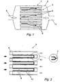
- figures 1 and 2 show a conventional particulate filter 1 including a body 2 generally enclosing a monolith 3 which in turn includes a plurality of tubular cells 4 each defined by a porous ceramic wall 5 and each having an alternating end blanked off by a ceramic plug 6. It is also known, but uncommon, for each alternating end to be blanked off by crimping 7, as shown in the optional view within figure 2.
- Exhaust gases entering the filter via an inlet port 8 are compelled to pass into alternate cells of the monolith and through a corresponding wall 9, with up to 90% of particulate mass thus being filtered by deposition on an inner wall surface 10.
- the cleaned exhaust gases exit the filter via an outlet port 11.
- the filter would be regenerated by oxidation of the collected particulates, either at set intervals or continuously, resulting in their conversion into small amounts of carbon dioxide.
- the conventional apparatus for initiating and controlling oxidation is not shown in the figures and is not required for the present invention.
- the present invention relates to the automatic regeneration in use of a particulate filter of a type including a ceramic monolith, the deposited particulates being autoselectively sensed and oxidised at an ultra-low level of particulate loading within the filter. As a result, relatively small filters may be used.
- the apparatus of the present invention provides the required extra energy for rapid and efficient oxidation of trapped particulate by an electrical input of relatively low power consumption in the form of an atmospheric glow discharge as will become clear.
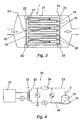
- Figure 3 relates to an apparatus of a first embodiment of the present invention in which a point electrode 15 is held by a support means 16 axially spaced apart from a first end 17 of the monolith, for example by a distance of between 4 and 6 mm.
- the support means 16 is perforated to permit the passage of exhaust gases therethrough.
- a counter electrode is provided at a second (downstream) end 18 of the monolith and may comprise individual electrodes (not shown) but is in the example provided in the form of a perforated or mesh plate 19 located axially adjacent to, and in electrical contact with, the second end of the monolith.
- the plate 19 is not directly in contact with the monolith but is closely spaced apart from the monolith, for example by a distance of up to 4 mm, and connected thereto by electrical connections 20.
- the counter electrode plate 19 is formed from perforated or meshed electrically conductive material such as steel or copper.
- the monolith may be supported within the filter body by an electrically insulated mounting sleeve 21.
- the electrode support means 16 adjacent to the first end of the monolith and the plate 19 adjacent to the second end of the monolith are supported within the filter body by electrically insulating mountings 22.
- Alternatives, for example support by the monolith (not shown) will be readily apparent.
- Electrical feed and return conductors 23, 24 are connected to the electrode and the screen and taken out of the filter via apertures (not shown).
- FIG. 4 An experimental laboratory apparatus 30 operating from a 230 volt power supply 31 is shown in figure 4.
- the power supply generates short square-wave pulses at a frequency of 20 kHz with a duration of about 12 ⁇ and a zero voltage period of about 13 ⁇ .
- a ferrite core transformer 32 wound to have a low self-inductance, steps up the output voltage to 10 kV.
- the frequency of 20 kHz is outside of the normal human audio range upper limit of 16-18 kHz and is a relatively safe frequency in conjunction with the current flow of the apparatus.
- a side 33 of a secondary winding of the transformer is connected to ten 47 ⁇ , 10 W, low inductance thick film resistors to limit the discharge current.
- the thick film resistors minimise unpredictable increases in resistance due to skin effect at high frequency which could affect accuracy of measurement during testing and their low inductance reduces parasitic oscillation. Spirally-wire-wound resistors were found to give adverse skin-effects.
- the monolith 3 used for the experimental laboratory work was a standard unit of 145 mm diameter and 150 mm length constructed from cordierite. For convenience in the initial experimental apparatus, the monolith was placed axially upright with the second end 18 bearing on the plate 19.
- the current in primary circuit I 1 was measured with a clip-on current probe having a frequency response of DC to 100 kHz and the output was recorded on one channel of a digital oscilloscope sampling at 5 megasamples per second.
- the secondary current I 2 was obtained by measuring the voltage drop across a 2 ⁇ non-inductive resistance (not shown) on the earthed side of the output.
- the voltage output of the secondary winding of the transformer and the voltage across a gap between the discharge side of the electrode 15 and the monolith 3 were measured with a high voltage probe with a bandwidth of 75 MHz.
- the oscilloscope voltage probe was wrapped in aluminium foil to act as a shield against electromagnetic pick-up from corona discharge.
- the voltage and current waveforms for a discharge across a 4 mm gap to the monolith are shown in figure 5.
- a positive voltage pulse was applied to the transformer, there was a current pulse of approximately 13 A followed by a negative current pulse. This can be attributed entirely to the behaviour of the transformer on no-load which is dominated by its self-capacitance.
- the total current in the secondary winding was about 25 mA mainly due to corona and capacitive current. Corona effects in the apparatus were minimised by avoiding sharp edges on conductor ends.
- the voltage across the secondary winding rose to 10 kV in ⁇ before falling to 2 kV for the remainder of the pulse.
- the same pulse shape was seen for the voltage measured across the gap with a peak voltage of 5 kV.
- the current in the secondary circuit sharply rises to a peak of 3,5 mA. This rise precedes any measured significant voltage rise and is probably due to the capacitance of the supply circuit, including the transformer 32.
- the small current measure suggests that most of the 25 mA derived above goes into the corona and capacitive current to earth from the transformer windings and other parts of the circuit.
- the discharge currently of 3,5 mA implies that the total impedance of the circuit including the resistors could be as high as 2,8 M ⁇ .
- the low value of discharge current estimated is consistent with the power loss and hence current determined from the power loss in the thick film stabilising resistors 34.
- the voltage spikes preceding each rise in current were caused by the onset of corona.
- the supply circuit behaved more as an electrical transmission line with distributed values of capacitance to earth and resistance corresponding to the corona loss.
- the monolith itself can behave like a transmission line with discharges in series with resistance and capacitance.
- the results from the experimental apparatus were used to derive a simplified equivalent circuit 37 using lumped components as shown in figure 6.
- the transformer 32 has significant capacitance (C 1 and C 2 ) because of the geometry of the low inductance windings.
- the discharge to the monolith 3 behaves as a resistor Rd connected in series with a small capacitance C T .
- C 3 represents the capacitance to earth, Rc the parallel resistance of the connecting circuit of the supply and Rd the corona discharge.
- Figure 7 shows the relationship between the peak gap voltage measured against electrode height above the monolith. With 10 kV pulses from the secondary winding of the transformer, breakdown and discharge occurs only when the electrode height is less than 6 mm. The step in the gap voltage where it is constant with height below 6 mm also suggests that the monolith behaves as a capacitor.
- Figure 8 shows the variation of the peak current with electrode height. Again a clear step is visible corresponding to the onset of discharge, the discharge only occurring and causing current flow below 6 mm. The small current above 6 mm can be attributed to the effects of corona.
- Figure 9 shows the estimated peak power of only the discharge (i.e. ignoring corona) calculated from the above measurements. While the discharge occurs, it is estimated that the peak power is about 20 W. The mean power (r.m.s.) however is likely to be considerably less than this due to the duty cycle of the system. It is estimated here that the system has a duty cycle of 50% corresponding to 10 W.
- Figure 10 shows the electrical measurements made on a clean monolith with an electrode height of 4 mm, in which no apparent discharge is present. The many spikes apparent indicate that corona current is dominant. Other longer period fluctuations are due to voltage pick-up.
- the monolith 3 of the experimental apparatus was heavily loaded in particulate from a diesel engine run under high load. As the heavily loaded monolith became progressively cleaner during testing, proving of the apparatus and method at various levels of particulate loading was automatically facilitated. Further tests were then carried out with a clean monolith in order to provide validation of the apparatus and method under extremes of particulate loading.
- the monolith 3 was sectioned and positioned so that discharge activities could be visually observed.
- a glass slide (not shown) was attached to the monolith to provide a viewing window but was not considered essential.
- the second end of the monolith was electrically connected to the return electrical circuit by means of an electrically conductive mesh in electrical contact with the monolith as already described in conjunction with figure 4.
- a video recording was taken of the progress of discharges 40 with time, stills from which are represented by the line drawings of figure 11.
- the discharge was observed to seek out particulate deposits 41 over a radius of 7,5 mm and after 13 minutes in conjunction with a fully loaded monolith (figure 2) it had cleaned two channels to a depth of 15 mm.
- the experimental apparatus described above included, for one test, a monolith fully loaded with particulate to validate the apparatus and method under the most adverse particulate loading. It will be understood that this level of loading was for testing purposes only.
- the invention unlike prior art arrangements, can operate without requiring high loading levels. In consequence, commencement in use with a relatively clean monolith subjected to a diesel engine exhaust gas flow will avoid a prolonged and continuous regeneration energy requirement over a substantial volume of the monolith, the particulate being targeted by the apparatus at almost the instant of deposition. The current needed for regeneration will depend to an extent upon the level of particulate being deposited.
- Figure 12 shows the mechanism of atmospheric gas discharge penetration into the cells of the monolith. As the discharge rapidly seeks out and oxidises particles 41 deposited on a wall surface 10 out of a cell 42, the local areas 43 where oxidation takes place take on negative charges which direct the discharge further into the cell.
- the experimental apparatus and method described above may be adapted for use in vehicles by exchanging the 230 volt power supply 31 (figure 6) with a 12 or 24 volt direct current (DC) power supply 45 as provided by a conventional vehicle electrical system (not shown) and configuring the power source to provide the required high voltage and preferably 20 kHz frequency output.
- an indicator (not shown) could be provided to register to a vehicle operator any failure of the apparatus.
- the apparatus may include a plurality of point electrodes.
- Figure 14 shows an electrical arrangement for three point electrodes 15, each of which must be electrically stabilised by, for example, a 470 k ⁇ resistor 34 in each independent electrical feed conductor 23.
- Figure 15 shows four point electrodes 15 supported by a support means 50.
- the support means may be similar in configuration to the single electrode support means 16 in figure 3 or may include a gas flow straightening means such as is described with reference to Figure 19.
- the point electrodes are radially spaced apart from each other by a distance determined by calculation or experimentation as being the most effective in use. An initial spacing for experimentation purposes might be 10 mm.
- Perforations 51 are provided for the passage of exhaust gases through the electrode support means 50.
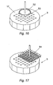
- a plate electrode 52 is used in place of single or multiple point electrodes 15.
- the plate electrode is manufactured from an electrically conductive material, preferable metal and for example copper, and has an area approximately corresponding to a target cleaning area (not shown) of the first end 17 of the monolith 3.
- the plate electrode has a turned-up periphery 53 to avoid unbalanced electrical discharges which could otherwise arise.
- the plate electrode may be provided in multiple form (not shown) in a similar manner to the multiple point electrode arrangement described in relation to figure 15, with the number of plate electrodes depending at least upon the total area of the monolith to be cleaned and their impact on gas flows into the monolith
- the plate electrode 52 of figure 16 was replaced with a mesh electrode 54 of similar area.
- the mesh electrode is manufactured from preferably metal and may be in the form of a perforated sheet-like material but it is preferably in the form of a wire mesh material.
- An advantage of the mesh electrode 54 over the plate electrode 52 is a much smaller obstruction to gas flows.
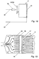
- Figure 18 shows a simplified electrical circuit diagram for a single plate or mesh electrode apparatus.
- a gas flow tube-stack 55 placed in axial alignment with, but spaced apart from, the first end 17 of the monolith 3 will help to direct the flow and hence will more favourable direct the electrical discharge 40 (figure 13).
- the tube-stack 55 has a length of, in this example, 35 mm and may be configured (not shown) to facilitate mounting of the electrode(s) which will be located between the tube-stack and the first end of the monolith.
- the tube-stack may be used in conjunction with any of the electrode configurations described herein.
- a portion of the tube-stack 55 may be coated or impregnatingly bonded with a layer of conducting material to produce a surface electrode.
- the surface electrode may be formed by dipping or spraying part or all of the tube-stack 55 using hot molten silicon or other suitable conducting material.
- the optimum distance between the tube stack surface electrode and the monolith is between 4 and 6 mm.
- the apparatus of the present invention in its several embodiments will autoselectively and rapidly seek and oxidise particulates deposited in the monolith with the benefit that the monolith may be significantly shorter than in conventional apparatus so far as allowance for exhaust gas back-pressure is concerned.
- the atmospheric gas discharge of the present invention may break up into smaller discharges between particulate deposits deep down in the monolith, in some configurations of apparatus and particulate deposits, there may occur a situation where the discharges do not reliably penetrate fully through the monolith.
- Figure 20 relates to an apparatus of a further embodiment to overcome the fore-mentioned two particular concerns.
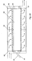
- a slab-like monolith 60 (having the general structure of the monoliths illustrated in figures 1 to 3) is positioned within and spaced apart from a filter body 61 by electrically insulating supports 62, 63.
- the monolith is provided with associated electrodes 66 and counter electrodes 67, preferably in perforated (mesh) form, together with electrical connectors 20 and conductors 23, 24 in general accordance with one or more previous embodiments.
- electrodes 66 and electrical connection thereto by conductor 23 are shown in the figure in simplified form but may of course be as described in any of the other embodiments of the invention.
- the monolith may, if required, be provided with a gas flow straightener as already described with reference to figure 19 but not however shown in figure 20.
- the exhaust gases entering the filter will pass through the monolith 60 which, whilst presenting a relatively large cell wall permeable surface area, also provides a usefully short path therethrough to ensure thorough penetration of the atmospheric glow discharges under all conditions of use.
- the cells of the slab-like monolith 60 have alternate ends blanked off by crimping rather than plugging (not shown, but refer to figure 2) in order to maximise the effective length of each cell.
- This slab-like topography of monolith would not be acceptable in conventional particulate filters which require monolith cells to be relatively deep in order to provide for an acceptable gas flow when the monolith is holding a heavy particulate deposit.
- the present example includes a ceramic monolith 60 to perform the filtering function it may be practicable to alternatively include a ceramic fibre, foam, membrane, sheet or pad.
- Figure 21 shows an apparatus in accordance with a further embodiment of the present invention in which a surface electrode 65 is provided in the form of a layer of conducting material coated or impregnatingly bonded to an end of the porous ceramic monolith 3, 60.
- the surface electrode may be formed by dipping or spraying part or all of an end 66 of the monolith using hot molten silicon or other suitable conducting material, a small quantity of which will be absorbed into the end of the monolith and will solidify to form a discrete and securely bonded surface layer.
- a downstream end of the monolith is particularly suitable for providing with an impregnated surface electrode which will act in this instance as a counter electrode.
- the counter electrode may be electrically stabilised by a suitable composition and/or configuration of impregnating material, and may be connected to a return conductor 23 to enable discharges from an electrode of any type already described herein to auto-selectively enter and clean any cell of the monolith.
- the autoselectively regenerating particulate filter apparatus and method of the present invention is intended for the exhaust system of diesel-fuelled internal combustion engines and has been primarily described as such but may be adapted for other equipment producing combustible particles.
Landscapes
- Chemical & Material Sciences (AREA)
- Geometry (AREA)
- Chemical Kinetics & Catalysis (AREA)
- Physics & Mathematics (AREA)
- Engineering & Computer Science (AREA)
- Combustion & Propulsion (AREA)
- Mechanical Engineering (AREA)
- General Engineering & Computer Science (AREA)
- Processes For Solid Components From Exhaust (AREA)
- Filtering Of Dispersed Particles In Gases (AREA)
- Filtering Materials (AREA)
- Physical Or Chemical Processes And Apparatus (AREA)
- Solid-Sorbent Or Filter-Aiding Compositions (AREA)
- Exhaust Gas After Treatment (AREA)
- Treating Waste Gases (AREA)
- Medicines Containing Plant Substances (AREA)
- Treatment Of Liquids With Adsorbents In General (AREA)
Claims (26)
- Un appareil pour retirer des particules d'un flux de gaz comportant un filtre à monolithe céramique (3) au travers duquel du gaz peut être amené à s'écouler, une pluralité de premières électrodes (15) destinées à produire des décharges luminescentes atmosphériques localisées près d'une première extrémité (17) du filtre (3) mais espacées de celle-ci, et au moins une deuxième contre-électrode (19) à distance des premières électrodes (15) et située dans un emplacement qui se trouve à l'utilisation en aval des premières électrodes (15), les électrodes étant raccordées à une alimentation en tension alternative (31) générant une tension alternative dans une fréquence comprise dans la gamme allant de 1 kHZ à 200 kHZ, caractérisé en ce que chaque première électrode (15) est stabilisée de façon électrique par un élément d'impédance dédié (34).
- Un appareil conformément à la revendication 1, dans lequel le filtre (3) a une profondeur faisant moins de 100 mm.
- Un appareil conformément soit à la revendication 1, soit à la revendication 2, dans lequel la profondeur dudit filtre (3) est comprise dans la gamme allant de 10 mm à 25 mm.
- Un appareil conformément à n'importe quelle revendication précédente, dans lequel l'appareil comporte entre deux et quatre premières électrodes (15).
- Un appareil conformément à n'importe quelle revendication précédente, dans lequel chaque élément d'impédance (34) comporte une résistance électrique.
- Un appareil conformément à n'importe quelle revendication précédente, dans lequel chaque première électrode est raccordée à l'alimentation en tension alternative (31) par un conducteur d'alimentation électrique indépendant dédié (23), et dans lequel chaque élément d'impédance (34) est localisé sur un conducteur d'alimentation électrique respectif (23) entre l'alimentation en tension alternative (31) et une première électrode respective (15).
- Un appareil conformément à n'importe quelle revendication précédente, dans lequel le filtre (3) comporte une pluralité de cellules tubulaires (42) qui s'étendent sur la profondeur du monolithe (3).
- Un appareil conformément à n'importe quelle revendication précédente, dans lequel chaque première électrode (15) comporte une électrode ponctuelle.
- Un appareil conformément à n'importe quelle revendication précédente, dans lequel chaque première électrode (15) comporte une pluralité d'emplacements de décharge.
- Un appareil conformément à n'importe quelle revendication précédente, dans lequel la ou chaque contre-électrode (19) comporte une pluralité d'emplacements de décharge.
- Un appareil tel que revendiqué dans n'importe quelle revendication précédente, dans lequel la source de tension (31) génère une tension alternative dans une gamme de fréquence allant de 18 kHz à 30 kHz.
- Un appareil conformément à n'importe quelle revendication précédente, dans lequel l'alimentation en tension (31) génère une tension alternative dans une gamme de fréquence allant de 20 kHz à 25 kHz.
- Un appareil conformément à n'importe quelle revendication précédente, dans lequel la source de tension (31) fournit une tension de sortie en circuit ouvert comprise entre 5 kV et 25 kV.
- Un appareil conformément à n'importe quelle revendication précédente, comportant en outre un empilage de tubes d'écoulement de gaz (55), comportant une pluralité de cellules tubulaires placées en alignement axiale avec une première extrémité (17) du filtre (3), mais espacées et en amont de celle-ci.
- Un appareil conformément à n'importe quelle revendication précédente monté au sein d'un corps de filtre (2), lequel corps (2) est pourvu d'ouvertures destinées à l'arrivée et à l'évacuation de gaz.
- Un procédé de retrait de particules d'un flux de gaz comportant les étapes : d'amener le gaz à s'écouler au travers d'un filtre à monolithe céramique (3) de sorte que des particules soient séparées de l'écoulement de gaz et piégées par le filtre (3), de positionner une pluralité de premières électrodes (15) près d'une première extrémité (17) du filtre (3) mais espacées de celle-ci, de positionner au moins une contre-électrode (19) à un emplacement à distance des premières électrodes (15) et en aval de celles-ci, et d'appliquer une tension alternative à une fréquence comprise dans la gamme allant de 1 kHz à 200 kHz entre les électrodes de manière à générer des décharges luminescentes atmosphériques depuis les premières électrodes (15), le procédé étant caractérisé par le fait de munir chaque première électrode (15) d'un élément d'impédance dédié (34) adapté pour stabiliser de façon électrique chaque première électrode respective (15).
- Un procédé conformément à la revendication 16, dans lequel le filtre (3) a une profondeur faisant moins de 100 mm.
- Un appareil conformément soit à la revendication 16, soit à la revendication 17, dans lequel la profondeur dudit filtre (3) est comprise dans la gamme allant de 10 mm à 25 mm.
- Un procédé conformément à n'importe lesquelles des revendications 16 à 18, dans lequel entre deux et quatre premières électrodes (15) sont positionnées près de la première extrémité (17) du filtre (3).
- Un procédé conformément à n'importe lesquelles des revendications 16 à 19, dans lequel chaque élément d'impédance (34) comporte une résistance électrique.
- Un procédé conformément à n'importe lesquelles des revendications 16 à 20 comportant en outre l'étape de raccorder chaque première électrode à l'alimentation en tension alternative (31) par un conducteur d'alimentation électrique indépendant dédié (23), et dans lequel chaque élément d'impédance (34) est localisé sur un conducteur d'alimentation électrique respectif (23) entre l'alimentation en tension alternative (31) et une première électrode respective (15).
- Un procédé conformément à n'importe lesquelles des revendications 16 à 21, dans lequel le filtre céramique (3) comporte une pluralité de cellules tubulaires (42) qui s'étendent sur la profondeur du monolithe (3).
- Un procédé conformément à n'importe lesquelles des revendications 16 à 22, dans lequel la ou chaque contre-électrode (19) est montée en contact électrique avec une deuxième extrémité aval (18) du filtre (3).
- Un procédé conformément à n'importe lesquelles des revendications 16 à 23, dans lequel il est fourni une tension alternative à une fréquence comprise dans la gamme allant de 18 kHz à 30 kHz.
- Un procédé conformément à n'importe lesquelles des revendications 16 à 24, dans lequel il est fourni une tension alternative à une fréquence comprise dans la gamme allant de 20 kHz à 25 kHz.
- Un procédé conformément à n'importe lesquelles des revendications 16 à 25, dans lequel la tension alternative est appliquée à une tension de sortie en circuit ouvert comprise entre 5 kV et 25 kV.
Applications Claiming Priority (3)
| Application Number | Priority Date | Filing Date | Title |
|---|---|---|---|
| GB9916254A GB2351923A (en) | 1999-07-12 | 1999-07-12 | Self-cleaning particulate filter utilizing electric discharge currents |
| GB9916254 | 1999-07-12 | ||
| EP00940617A EP1192335B1 (fr) | 1999-07-12 | 2000-06-26 | Filtre a particules regenerant autoselectif |
Related Parent Applications (2)
| Application Number | Title | Priority Date | Filing Date |
|---|---|---|---|
| EP00940617.4 Division | 2000-06-26 | ||
| EP00940617A Division EP1192335B1 (fr) | 1999-07-12 | 2000-06-26 | Filtre a particules regenerant autoselectif |
Publications (3)
| Publication Number | Publication Date |
|---|---|
| EP1460244A2 EP1460244A2 (fr) | 2004-09-22 |
| EP1460244A3 EP1460244A3 (fr) | 2005-06-29 |
| EP1460244B1 true EP1460244B1 (fr) | 2007-01-10 |
Family
ID=10857054
Family Applications (2)
| Application Number | Title | Priority Date | Filing Date |
|---|---|---|---|
| EP04013811A Expired - Lifetime EP1460244B1 (fr) | 1999-07-12 | 2000-06-26 | Filtre à particules avec régénération autosélective |
| EP00940617A Expired - Lifetime EP1192335B1 (fr) | 1999-07-12 | 2000-06-26 | Filtre a particules regenerant autoselectif |
Family Applications After (1)
| Application Number | Title | Priority Date | Filing Date |
|---|---|---|---|
| EP00940617A Expired - Lifetime EP1192335B1 (fr) | 1999-07-12 | 2000-06-26 | Filtre a particules regenerant autoselectif |
Country Status (9)
| Country | Link |
|---|---|
| US (2) | US6660068B1 (fr) |
| EP (2) | EP1460244B1 (fr) |
| JP (1) | JP4485107B2 (fr) |
| AT (1) | ATE313008T1 (fr) |
| AU (1) | AU5552900A (fr) |
| CA (1) | CA2378805C (fr) |
| DE (2) | DE60032951T2 (fr) |
| GB (1) | GB2351923A (fr) |
| WO (1) | WO2001004467A1 (fr) |
Families Citing this family (43)
| Publication number | Priority date | Publication date | Assignee | Title |
|---|---|---|---|---|
| GB2351923A (en) * | 1999-07-12 | 2001-01-17 | Perkins Engines Co Ltd | Self-cleaning particulate filter utilizing electric discharge currents |
| AT409653B (de) * | 1999-11-10 | 2002-10-25 | Fleck Carl M Dr | Verfahren und vorrichtung zum abscheiden von russpartikel aus einem abgasstrom, insbesondere einer diesel-brennkraftmaschine |
| DE60122688T2 (de) * | 2000-03-21 | 2008-02-07 | Silentor Holding A/S | Schalldämpfer mit einem oder mehreren porösen körpern |
| DE10130163B4 (de) * | 2000-11-21 | 2012-01-12 | Siemens Ag | Anordnung zur Verminderung kohlenstoffhaltiger Partikelemissionen von Dieselmotoren |
| JP4265120B2 (ja) * | 2001-07-19 | 2009-05-20 | 株式会社豊田中央研究所 | 内燃機関の排ガス浄化装置 |
| JP3685106B2 (ja) * | 2001-08-08 | 2005-08-17 | トヨタ自動車株式会社 | 排気浄化装置 |
| FR2830275B1 (fr) * | 2001-10-01 | 2004-06-11 | Renault | Systeme de traitement des gaz d'echappement d'un moteur a combustion |
| FR2830566B1 (fr) * | 2001-10-04 | 2004-02-27 | Renault | Systeme de traitement des gaz d'echappement d'un moteur a combustion |
| DE10229881B4 (de) * | 2002-07-03 | 2008-01-31 | Siemens Ag | Plasma-Russfilter |
| JP2004176703A (ja) * | 2002-10-02 | 2004-06-24 | Toshiba Corp | ガス浄化装置およびガス浄化方法並びにガス浄化装置に使用する放電反応体 |
| JP4276474B2 (ja) * | 2003-06-04 | 2009-06-10 | 日野自動車株式会社 | 排気浄化装置 |
| JP2005061246A (ja) * | 2003-08-19 | 2005-03-10 | Toyota Motor Corp | 排気浄化装置 |
| JP4396440B2 (ja) * | 2003-10-09 | 2010-01-13 | 株式会社デンソー | 内燃機関の排気処理装置 |
| FR2861131B1 (fr) * | 2003-10-17 | 2008-02-22 | Renault Sa | Systeme de filtration electrostatique de particules de suie des gaz d'echappement d'un moteur a combustion interne et procede de regeneration d'un tel systeme |
| WO2005113951A1 (fr) * | 2004-05-24 | 2005-12-01 | Hino Motors, Ltd. | Purificateur de gaz d'échappement |
| DE102004029524B4 (de) * | 2004-06-18 | 2007-12-06 | Robert Bosch Gmbh | Verfahren und Vorrichtung zur definierten Regeneration von rußbehafteten Oberflächen |
| JP4637531B2 (ja) * | 2004-08-26 | 2011-02-23 | 京セラ株式会社 | 排気ガス処理用セラミック部材および排気ガス処理装置 |
| US20060231207A1 (en) * | 2005-03-31 | 2006-10-19 | Rebinsky Douglas A | System and method for surface treatment |
| JP3897798B2 (ja) * | 2005-06-08 | 2007-03-28 | 日新電機株式会社 | 排ガス浄化方法及び排ガス浄化装置 |
| US7260930B2 (en) * | 2005-07-26 | 2007-08-28 | Caterpillar Inc. | Radio frequency-based particulate loading monitoring system |
| GB2429417B (en) | 2005-08-25 | 2010-08-11 | Perkins Engines Co Ltd | Autoselective regenerating particulate filter |
| US8205441B2 (en) * | 2006-03-24 | 2012-06-26 | GM Global Technology Operations LLC | Zone heated inlet ignited diesel particulate filter regeneration |
| KR100793892B1 (ko) * | 2006-09-26 | 2008-01-15 | 현대자동차주식회사 | 매연여과장치용 입자상 물질 여과 시스템 |
| WO2008096852A1 (fr) * | 2007-02-09 | 2008-08-14 | Ngk Insulators, Ltd. | Structure en nid d'abeille pour un capteur de fine particule |
| JP4482016B2 (ja) * | 2007-06-29 | 2010-06-16 | 株式会社ノリタケカンパニーリミテド | 複合セラミックスの製造方法、複合セラミックス、およびセラミックフィルタアセンブリ |
| US8671668B2 (en) | 2007-08-10 | 2014-03-18 | GM Global Technology Operations LLC | Generator powered electrically heated diesel particulate filter |
| US8388741B2 (en) | 2007-08-14 | 2013-03-05 | GM Global Technology Operations LLC | Electrically heated particulate filter with reduced stress |
| US8252077B2 (en) | 2007-09-17 | 2012-08-28 | GM Global Technology Operations LLC | Electrically heated particulate filter heater insulation |
| US7901475B2 (en) | 2008-01-18 | 2011-03-08 | Gm Global Technology Operations, Inc. | Diesel particulate filter with zoned resistive heater |
| EP2169191B9 (fr) | 2008-09-30 | 2013-02-20 | Perkins Engines Company Limited | Méthode et dispositif de régénération d'un filtre. |
| WO2010037406A1 (fr) * | 2008-09-30 | 2010-04-08 | Perkins Engines Company Limited | Procédé et appareil pour régénérer un filtre |
| KR101048126B1 (ko) | 2008-10-02 | 2011-07-08 | 현대자동차주식회사 | 배기가스 정화장치 |
| US8051644B2 (en) * | 2009-02-18 | 2011-11-08 | GM Global Technology Operations LLC | Electrically heated particulate filter zone-based post fuel injection system |
| US8813557B2 (en) * | 2011-04-12 | 2014-08-26 | Bosch Automotive Service Solutions Llc | Diesel particulate filter flow rate measuring apparatus and method |
| US9488085B2 (en) * | 2013-09-18 | 2016-11-08 | Advanced Technology Emission Solutions Inc. | Catalytic converter structures with induction heating |
| US9597627B2 (en) * | 2014-10-19 | 2017-03-21 | Wei Zhang (William) | Regenerative air purification system and method |
| USRE46804E1 (en) * | 2014-01-07 | 2018-04-24 | Wei Zhang | Regenerative air purification system and method |
| US10428707B2 (en) * | 2014-02-25 | 2019-10-01 | Southwest Research Institute | Partial-flow diesel particulate filter using pressure regulated bypass |
| ITUB20161246A1 (it) * | 2016-03-02 | 2017-09-02 | Ecospray Tech Srl | Apparato filtrante ad efficienza migliorata e processo per la depolverazione di gas |
| CN109356686B (zh) * | 2018-11-05 | 2023-06-09 | 卢宝良 | 柴油发动机尾气黑烟净化器 |
| EP3966441B1 (fr) | 2019-05-10 | 2024-03-06 | Donaldson Company, Inc. | Appareil de rétention pour disposition en treillis métallique |
| US11673007B2 (en) | 2020-12-24 | 2023-06-13 | Saied Tousi | Personal protective equipment that employs nanoparticles of two different metals that generate an electric field for inactivating microorganisms |
| US11471713B2 (en) * | 2020-12-24 | 2022-10-18 | Mohammad Taghi Fatehi | Personal protective equipment that employs an electric field for inactivating microorganisms |
Family Cites Families (38)
| Publication number | Priority date | Publication date | Assignee | Title |
|---|---|---|---|---|
| US3979193A (en) * | 1972-07-03 | 1976-09-07 | Jack Sikich | Corona discharge apparatus |
| US4376637A (en) * | 1980-10-14 | 1983-03-15 | California Institute Of Technology | Apparatus and method for destructive removal of particles contained in flowing fluid |
| US4631452A (en) | 1981-03-19 | 1986-12-23 | Loughborough Consultants Limited | Apparatus and method for generating a plurality of electric discharges |
| GB2145310B (en) | 1981-03-19 | 1985-11-20 | Loughborough Consult Ltd | Generating a plurality of electric discharges, plasma torches |
| US4535589A (en) * | 1981-05-26 | 1985-08-20 | Nippon Soken, Inc. | Exhaust gas cleaning device for internal combustion engine |
| US4505107A (en) * | 1981-10-26 | 1985-03-19 | Nippondenso Co., Ltd. | Exhaust gas cleaning apparatus |
| DE3608801A1 (de) * | 1986-03-15 | 1987-09-17 | Fev Forsch Energietech Verbr | Verfahren und vorrichtung zur regeneration von partikelfiltersystemen |
| US4866728A (en) | 1987-01-12 | 1989-09-12 | Jeco2 Lasers, Inc. | Electric discharge apparatus |
| DE3705979A1 (de) * | 1987-02-25 | 1988-09-08 | Navsat Gmbh | Abgasrussfilter |
| GB8708115D0 (en) * | 1987-04-04 | 1987-05-13 | Woodhouse Derek Alfred | Coagulation treatment of fluids |
| DE3723154A1 (de) * | 1987-07-14 | 1989-01-26 | Navsat Gmbh | Vorrichtung fuer die abscheidung von russ aus dem abgasstrom eines verbrennungsmotors |
| US4979364A (en) * | 1988-03-11 | 1990-12-25 | Fleck Carl M | Diesel fuel exhaust gas filter |
| DE3829048A1 (de) | 1988-08-26 | 1990-03-01 | Beru Werk Ruprecht Gmbh Co A | Verfahren und vorrichtung zum regenerieren eines russpartikel-abbrennfilter |
| JPH0275314A (ja) * | 1988-09-09 | 1990-03-15 | Toyota Motor Corp | ディーゼル・パティキュレート捕集用フィルタ製造方法 |
| DE3834920A1 (de) * | 1988-10-13 | 1990-04-19 | Man Nutzfahrzeuge Ag | Verfahren und vorrichtung zum beseitigen von in einem abgasfilter einer brennkraftmaschine abgeschiedenem russ |
| IT1230455B (it) * | 1989-02-10 | 1991-10-23 | Sviluppo Materiali Spa | Dispositivo per l'abbattimento del particolato nei gas di combustione |
| JP3018457B2 (ja) * | 1990-10-05 | 2000-03-13 | 株式会社デンソー | 自己発熱型フィルタ |
| US5259190A (en) * | 1991-08-01 | 1993-11-09 | Corning Incorporated | Heated cellular structures |
| AU9146191A (en) * | 1991-10-25 | 1993-05-21 | Caterpillar Inc. | Method and apparatus for initiating regeneration in an engine exhaust particulate filter |
| DE4230630A1 (de) * | 1992-09-12 | 1994-03-17 | Amann & Soehne | Verfahren zur Herstellung oder zur Zerstörung von chemischen Verbindungen |
| DE4230631C2 (de) * | 1992-09-12 | 1996-08-08 | Amann & Soehne | Verfahren zur Entfernung von elektrisch leitenden Teilchen aus einem Gasstrom sowie Vorrichtung zur Durchführung des Verfahrens |
| JPH06146852A (ja) * | 1992-11-13 | 1994-05-27 | Senichi Masuda | デイーゼルエンジン排気ガス浄化装置 |
| GB9301433D0 (en) * | 1993-01-20 | 1993-03-17 | Atomic Energy Authority Uk | Gas purification |
| DE4416676C2 (de) | 1994-05-11 | 2002-11-07 | Siemens Ag | Vorrichtung zur Entgiftung von Abgasen aus mobilen Anlagen |
| JPH08312340A (ja) * | 1995-05-11 | 1996-11-26 | Usui Internatl Ind Co Ltd | 排気ガス浄化装置 |
| DE69629979T2 (de) * | 1995-06-02 | 2004-07-29 | Corning Inc. | Vorrichtung zur Entfernung von Kontaminationen aus Fluidströmen |
| SE504524C2 (sv) | 1995-07-03 | 1997-02-24 | Tetra Laval Holdings & Finance | Förpackningslaminat som kan värmebehandlas i fuktig atmosfär |
| AU6181496A (en) * | 1995-07-06 | 1997-02-05 | Carl Maria Fleck | Soot filter, in particular for diesel engine exhaust gases |
| DE19525407A1 (de) * | 1995-07-12 | 1997-01-16 | Henkel Kgaa | Schmierverfahren für schwere Umformungen |
| DE19530228C1 (de) | 1995-08-17 | 1996-04-11 | Lamm Alfred | Verschiebevorrichtung |
| ATA24696A (de) * | 1996-02-12 | 2000-10-15 | Fleck Carl M Dr | Vorrichtung zum reinigen von abgasen aus verbrennungskraftmaschinen |
| DE19610137A1 (de) * | 1996-03-14 | 1997-09-18 | Siemens Ag | Vorrichtung zur Abgasreinigung |
| DE19616197C2 (de) * | 1996-04-23 | 1998-04-09 | Fraunhofer Ges Forschung | Verfahren zur Behandlung von Abgas |
| DE19616206A1 (de) * | 1996-04-23 | 1997-11-13 | Fraunhofer Ges Forschung | Vorrichtung zur Nachbehandlung von Abgas durch Kombination von Gasentladung und Katalysator |
| US6245126B1 (en) * | 1999-03-22 | 2001-06-12 | Enviromental Elements Corp. | Method for enhancing collection efficiency and providing surface sterilization of an air filter |
| JP3575687B2 (ja) * | 1999-05-20 | 2004-10-13 | インスティテュート・フォー・アドバンスト・エンジニアリング | 内燃機関の排ガス浄化装置 |
| GB2351923A (en) * | 1999-07-12 | 2001-01-17 | Perkins Engines Co Ltd | Self-cleaning particulate filter utilizing electric discharge currents |
| EP1287242A1 (fr) * | 2000-06-01 | 2003-03-05 | Blue Planet Co., Ltd | Appareil pour eliminer la suie et no x? des gaz d'echappement de moteurs diesel |
-
1999
- 1999-07-12 GB GB9916254A patent/GB2351923A/en not_active Withdrawn
-
2000
- 2000-06-26 AT AT00940617T patent/ATE313008T1/de not_active IP Right Cessation
- 2000-06-26 DE DE60032951T patent/DE60032951T2/de not_active Expired - Lifetime
- 2000-06-26 JP JP2001509850A patent/JP4485107B2/ja not_active Expired - Fee Related
- 2000-06-26 EP EP04013811A patent/EP1460244B1/fr not_active Expired - Lifetime
- 2000-06-26 CA CA002378805A patent/CA2378805C/fr not_active Expired - Fee Related
- 2000-06-26 US US10/031,214 patent/US6660068B1/en not_active Expired - Lifetime
- 2000-06-26 WO PCT/GB2000/002451 patent/WO2001004467A1/fr not_active Ceased
- 2000-06-26 AU AU55529/00A patent/AU5552900A/en not_active Abandoned
- 2000-06-26 DE DE60024822T patent/DE60024822T2/de not_active Expired - Lifetime
- 2000-06-26 EP EP00940617A patent/EP1192335B1/fr not_active Expired - Lifetime
-
2003
- 2003-11-05 US US10/701,542 patent/US7144448B2/en not_active Expired - Lifetime
Also Published As
| Publication number | Publication date |
|---|---|
| US20040088955A1 (en) | 2004-05-13 |
| DE60024822T2 (de) | 2006-08-24 |
| GB9916254D0 (en) | 1999-09-15 |
| AU5552900A (en) | 2001-01-30 |
| JP4485107B2 (ja) | 2010-06-16 |
| US6660068B1 (en) | 2003-12-09 |
| JP2003504547A (ja) | 2003-02-04 |
| DE60032951D1 (de) | 2007-02-22 |
| DE60024822D1 (de) | 2006-01-19 |
| EP1192335B1 (fr) | 2005-12-14 |
| GB2351923A (en) | 2001-01-17 |
| DE60032951T2 (de) | 2007-10-31 |
| CA2378805C (fr) | 2009-01-06 |
| EP1460244A2 (fr) | 2004-09-22 |
| EP1192335A1 (fr) | 2002-04-03 |
| WO2001004467A1 (fr) | 2001-01-18 |
| CA2378805A1 (fr) | 2001-01-18 |
| US7144448B2 (en) | 2006-12-05 |
| EP1460244A3 (fr) | 2005-06-29 |
| ATE313008T1 (de) | 2005-12-15 |
Similar Documents
| Publication | Publication Date | Title |
|---|---|---|
| EP1460244B1 (fr) | Filtre à particules avec régénération autosélective | |
| US6321531B1 (en) | Method and apparatus for using free radicals to reduce pollutants in the exhaust gases from the combustion of a fuel | |
| US20050279084A1 (en) | Method and apparatus for the defined regeneration of sooty surfaces | |
| JP2012047722A (ja) | 粒子状物質検出センサとその異常判定方法 | |
| JP2008231930A (ja) | ハニカム構造体の微粒子堆積量測定方法 | |
| JP4142146B2 (ja) | 汚れを探知し、局所的に絶縁媒体を加熱するための装置 | |
| EP1890014B1 (fr) | Procédé et système de réduction des émissions de gaz d'échappement | |
| WO2016147711A1 (fr) | Système de détection de matière particulaire | |
| Chae et al. | Reduction of the particulate and nitric oxide from the diesel engine using a plasma chemical hybrid system | |
| JP2004346800A (ja) | ディーゼルエンジン用パティキュレートトラップ | |
| CN101273188B (zh) | 自动选择再生的颗粒过滤器 | |
| EP1564386B1 (fr) | Appareil et procédé d'évaluation de la charge en suies d'un filtre à particules | |
| JP2005061246A (ja) | 排気浄化装置 | |
| JP4855811B2 (ja) | 微粒子量検出システム | |
| WO2004109070A1 (fr) | Epurateur de gaz d'echappement | |
| Okubo et al. | Soot incineration of diesel particulate filter using honeycomb nonthermal plasma | |
| DE102004007041A1 (de) | Verfahren zum Betreiben eines Partikelfilters | |
| EP2169191B9 (fr) | Méthode et dispositif de régénération d'un filtre. | |
| JP2005232971A (ja) | 排気ガス浄化装置 | |
| JPH1089050A (ja) | 排気ガス用のフィルタ装置 | |
| Graupner et al. | Pulsed discharge regeneration of diesel particulate filters | |
| Mason et al. | Non-Thermal Particulate Filter Regeneration Using Rapid Pulse Electric Discharges | |
| US20140238233A1 (en) | Flame detection system for particulate filter regeneration | |
| JP2006170021A (ja) | 排ガス浄化装置 | |
| JPH0842325A (ja) | 内燃機関の排気微粒子浄化装置 |
Legal Events
| Date | Code | Title | Description |
|---|---|---|---|
| PUAI | Public reference made under article 153(3) epc to a published international application that has entered the european phase |
Free format text: ORIGINAL CODE: 0009012 |
|
| AC | Divisional application: reference to earlier application |
Ref document number: 1192335 Country of ref document: EP Kind code of ref document: P |
|
| AK | Designated contracting states |
Kind code of ref document: A2 Designated state(s): AT BE CH CY DE DK ES FI FR GB GR IE IT LI LU MC NL PT SE |
|
| PUAL | Search report despatched |
Free format text: ORIGINAL CODE: 0009013 |
|
| AK | Designated contracting states |
Kind code of ref document: A3 Designated state(s): AT BE CH CY DE DK ES FI FR GB GR IE IT LI LU MC NL PT SE |
|
| 17P | Request for examination filed |
Effective date: 20051223 |
|
| AKX | Designation fees paid |
Designated state(s): AT BE CH CY DE DK ES FI FR GB GR IE IT LI LU MC NL PT SE |
|
| GRAP | Despatch of communication of intention to grant a patent |
Free format text: ORIGINAL CODE: EPIDOSNIGR1 |
|
| GRAS | Grant fee paid |
Free format text: ORIGINAL CODE: EPIDOSNIGR3 |
|
| GRAA | (expected) grant |
Free format text: ORIGINAL CODE: 0009210 |
|
| AC | Divisional application: reference to earlier application |
Ref document number: 1192335 Country of ref document: EP Kind code of ref document: P |
|
| AK | Designated contracting states |
Kind code of ref document: B1 Designated state(s): AT BE CH CY DE DK ES FI FR GB GR IE IT LI LU MC NL PT SE |
|
| PG25 | Lapsed in a contracting state [announced via postgrant information from national office to epo] |
Ref country code: AT Free format text: LAPSE BECAUSE OF FAILURE TO SUBMIT A TRANSLATION OF THE DESCRIPTION OR TO PAY THE FEE WITHIN THE PRESCRIBED TIME-LIMIT Effective date: 20070110 Ref country code: NL Free format text: LAPSE BECAUSE OF FAILURE TO SUBMIT A TRANSLATION OF THE DESCRIPTION OR TO PAY THE FEE WITHIN THE PRESCRIBED TIME-LIMIT Effective date: 20070110 Ref country code: FI Free format text: LAPSE BECAUSE OF FAILURE TO SUBMIT A TRANSLATION OF THE DESCRIPTION OR TO PAY THE FEE WITHIN THE PRESCRIBED TIME-LIMIT Effective date: 20070110 Ref country code: LI Free format text: LAPSE BECAUSE OF FAILURE TO SUBMIT A TRANSLATION OF THE DESCRIPTION OR TO PAY THE FEE WITHIN THE PRESCRIBED TIME-LIMIT Effective date: 20070110 Ref country code: DK Free format text: LAPSE BECAUSE OF FAILURE TO SUBMIT A TRANSLATION OF THE DESCRIPTION OR TO PAY THE FEE WITHIN THE PRESCRIBED TIME-LIMIT Effective date: 20070110 Ref country code: CH Free format text: LAPSE BECAUSE OF FAILURE TO SUBMIT A TRANSLATION OF THE DESCRIPTION OR TO PAY THE FEE WITHIN THE PRESCRIBED TIME-LIMIT Effective date: 20070110 |
|
| REG | Reference to a national code |
Ref country code: GB Ref legal event code: FG4D |
|
| REG | Reference to a national code |
Ref country code: IE Ref legal event code: FG4D |
|
| REF | Corresponds to: |
Ref document number: 60032951 Country of ref document: DE Date of ref document: 20070222 Kind code of ref document: P |
|
| RAP2 | Party data changed (patent owner data changed or rights of a patent transferred) |
Owner name: PERKINS ENGINES COMPANY LIMITED |
|
| PG25 | Lapsed in a contracting state [announced via postgrant information from national office to epo] |
Ref country code: SE Free format text: LAPSE BECAUSE OF FAILURE TO SUBMIT A TRANSLATION OF THE DESCRIPTION OR TO PAY THE FEE WITHIN THE PRESCRIBED TIME-LIMIT Effective date: 20070410 |
|
| PG25 | Lapsed in a contracting state [announced via postgrant information from national office to epo] |
Ref country code: ES Free format text: LAPSE BECAUSE OF FAILURE TO SUBMIT A TRANSLATION OF THE DESCRIPTION OR TO PAY THE FEE WITHIN THE PRESCRIBED TIME-LIMIT Effective date: 20070421 |
|
| NLT2 | Nl: modifications (of names), taken from the european patent patent bulletin |
Owner name: PERKINS ENGINES COMPANY LIMITED Effective date: 20070328 |
|
| PG25 | Lapsed in a contracting state [announced via postgrant information from national office to epo] |
Ref country code: PT Free format text: LAPSE BECAUSE OF FAILURE TO SUBMIT A TRANSLATION OF THE DESCRIPTION OR TO PAY THE FEE WITHIN THE PRESCRIBED TIME-LIMIT Effective date: 20070611 |
|
| NLV1 | Nl: lapsed or annulled due to failure to fulfill the requirements of art. 29p and 29m of the patents act | ||
| REG | Reference to a national code |
Ref country code: CH Ref legal event code: PL |
|
| ET | Fr: translation filed | ||
| PLBE | No opposition filed within time limit |
Free format text: ORIGINAL CODE: 0009261 |
|
| STAA | Information on the status of an ep patent application or granted ep patent |
Free format text: STATUS: NO OPPOSITION FILED WITHIN TIME LIMIT |
|
| 26N | No opposition filed |
Effective date: 20071011 |
|
| PG25 | Lapsed in a contracting state [announced via postgrant information from national office to epo] |
Ref country code: BE Free format text: LAPSE BECAUSE OF FAILURE TO SUBMIT A TRANSLATION OF THE DESCRIPTION OR TO PAY THE FEE WITHIN THE PRESCRIBED TIME-LIMIT Effective date: 20070110 |
|
| PG25 | Lapsed in a contracting state [announced via postgrant information from national office to epo] |
Ref country code: MC Free format text: LAPSE BECAUSE OF NON-PAYMENT OF DUE FEES Effective date: 20070630 |
|
| PG25 | Lapsed in a contracting state [announced via postgrant information from national office to epo] |
Ref country code: GR Free format text: LAPSE BECAUSE OF FAILURE TO SUBMIT A TRANSLATION OF THE DESCRIPTION OR TO PAY THE FEE WITHIN THE PRESCRIBED TIME-LIMIT Effective date: 20070411 Ref country code: IT Free format text: LAPSE BECAUSE OF FAILURE TO SUBMIT A TRANSLATION OF THE DESCRIPTION OR TO PAY THE FEE WITHIN THE PRESCRIBED TIME-LIMIT Effective date: 20070110 |
|
| PG25 | Lapsed in a contracting state [announced via postgrant information from national office to epo] |
Ref country code: IE Free format text: LAPSE BECAUSE OF NON-PAYMENT OF DUE FEES Effective date: 20070626 |
|
| PG25 | Lapsed in a contracting state [announced via postgrant information from national office to epo] |
Ref country code: CY Free format text: LAPSE BECAUSE OF FAILURE TO SUBMIT A TRANSLATION OF THE DESCRIPTION OR TO PAY THE FEE WITHIN THE PRESCRIBED TIME-LIMIT Effective date: 20070110 |
|
| PG25 | Lapsed in a contracting state [announced via postgrant information from national office to epo] |
Ref country code: LU Free format text: LAPSE BECAUSE OF NON-PAYMENT OF DUE FEES Effective date: 20070626 |
|
| PGFP | Annual fee paid to national office [announced via postgrant information from national office to epo] |
Ref country code: GB Payment date: 20140527 Year of fee payment: 15 |
|
| PGFP | Annual fee paid to national office [announced via postgrant information from national office to epo] |
Ref country code: FR Payment date: 20140527 Year of fee payment: 15 |
|
| PGFP | Annual fee paid to national office [announced via postgrant information from national office to epo] |
Ref country code: DE Payment date: 20150630 Year of fee payment: 16 |
|
| GBPC | Gb: european patent ceased through non-payment of renewal fee |
Effective date: 20150626 |
|
| REG | Reference to a national code |
Ref country code: FR Ref legal event code: ST Effective date: 20160229 |
|
| PG25 | Lapsed in a contracting state [announced via postgrant information from national office to epo] |
Ref country code: GB Free format text: LAPSE BECAUSE OF NON-PAYMENT OF DUE FEES Effective date: 20150626 |
|
| PG25 | Lapsed in a contracting state [announced via postgrant information from national office to epo] |
Ref country code: FR Free format text: LAPSE BECAUSE OF NON-PAYMENT OF DUE FEES Effective date: 20150630 |
|
| REG | Reference to a national code |
Ref country code: DE Ref legal event code: R119 Ref document number: 60032951 Country of ref document: DE |
|
| PG25 | Lapsed in a contracting state [announced via postgrant information from national office to epo] |
Ref country code: DE Free format text: LAPSE BECAUSE OF NON-PAYMENT OF DUE FEES Effective date: 20170103 |