EP1460307A2 - Spanneinrichtung für einen Zugmitteltrieb - Google Patents
Spanneinrichtung für einen Zugmitteltrieb Download PDFInfo
- Publication number
- EP1460307A2 EP1460307A2 EP04005064A EP04005064A EP1460307A2 EP 1460307 A2 EP1460307 A2 EP 1460307A2 EP 04005064 A EP04005064 A EP 04005064A EP 04005064 A EP04005064 A EP 04005064A EP 1460307 A2 EP1460307 A2 EP 1460307A2
- Authority
- EP
- European Patent Office
- Prior art keywords
- spring
- compression spring
- guide sleeves
- clamping device
- tensioning
- Prior art date
- Legal status (The legal status is an assumption and is not a legal conclusion. Google has not performed a legal analysis and makes no representation as to the accuracy of the status listed.)
- Granted
Links
Images


Classifications
-
- F—MECHANICAL ENGINEERING; LIGHTING; HEATING; WEAPONS; BLASTING
- F16—ENGINEERING ELEMENTS AND UNITS; GENERAL MEASURES FOR PRODUCING AND MAINTAINING EFFECTIVE FUNCTIONING OF MACHINES OR INSTALLATIONS; THERMAL INSULATION IN GENERAL
- F16H—GEARING
- F16H7/00—Gearings for conveying rotary motion by endless flexible members
- F16H7/08—Means for varying tension of belts, ropes or chains
- F16H7/10—Means for varying tension of belts, ropes or chains by adjusting the axis of a pulley
- F16H7/12—Means for varying tension of belts, ropes or chains by adjusting the axis of a pulley of an idle pulley
- F16H7/1254—Means for varying tension of belts, ropes or chains by adjusting the axis of a pulley of an idle pulley without vibration damping means
- F16H7/1281—Means for varying tension of belts, ropes or chains by adjusting the axis of a pulley of an idle pulley without vibration damping means where the axis of the pulley moves along a substantially circular path
-
- F—MECHANICAL ENGINEERING; LIGHTING; HEATING; WEAPONS; BLASTING
- F16—ENGINEERING ELEMENTS AND UNITS; GENERAL MEASURES FOR PRODUCING AND MAINTAINING EFFECTIVE FUNCTIONING OF MACHINES OR INSTALLATIONS; THERMAL INSULATION IN GENERAL
- F16H—GEARING
- F16H7/00—Gearings for conveying rotary motion by endless flexible members
- F16H7/08—Means for varying tension of belts, ropes or chains
- F16H2007/0802—Actuators for final output members
- F16H2007/0806—Compression coil springs
-
- F—MECHANICAL ENGINEERING; LIGHTING; HEATING; WEAPONS; BLASTING
- F16—ENGINEERING ELEMENTS AND UNITS; GENERAL MEASURES FOR PRODUCING AND MAINTAINING EFFECTIVE FUNCTIONING OF MACHINES OR INSTALLATIONS; THERMAL INSULATION IN GENERAL
- F16H—GEARING
- F16H7/00—Gearings for conveying rotary motion by endless flexible members
- F16H7/08—Means for varying tension of belts, ropes or chains
- F16H2007/0863—Finally actuated members, e.g. constructional details thereof
- F16H2007/0874—Two or more finally actuated members
Definitions
- the invention relates to a tensioning device for a traction mechanism drive, in particular for driving various types of work devices on agricultural harvesting machines, according to the preamble of patent claim 1.
- V-belt drives are used to drive the individual functional assemblies, which have to ensure a drive power transmission corresponding to the machine performance.
- a tension of the V-belts necessary for the respective power transmission is necessary. This is achieved by means of a tensioning device assigned to each V-belt drive.
- Such devices are already known in various versions.
- EP 0 126 808 B1 shows a spring-loaded tensioning device with integrated overload protection for a V-belt drive, in which a compression spring with a tensioning device transmits the tensioning force via a pull rod to a pivotable double lever. At the other end of the double lever, a tensioning roller is mounted, which acts on the V-belt to be tensioned in such a way that the belt tension required for the drive force transmission is available to a sufficient extent.
- the compression spring is arranged on a spring holder between abutments on the pull rod and a fixed holder connected to the machine frame. The required preload of the compression spring is achieved by turning the abutment on the Drawbar set.
- this tensioning device requires a relatively high production cost.
- the spring holder for the compression spring essentially consists of a support and guide sleeve fastened to an abutment, which is screwably connected to a coupling rod.
- the tension of the compression spring arranged on it is adjusted.
- the spring tension is transferred via the coupling rod to a double lever on which a tensioning roller for a V-belt is mounted.
- the compression spring is pretensioned when the tensioning roller is released, in that positionally secured spacers are attached between the spring support and the spring end and are removed again after assembly.
- the spring tension set in this way then acts on the tensioning pulley of the V-belt drive. Since the work required for pretensioning the compression spring is very labor-intensive and labor-intensive and, moreover, the production outlay for the required individual parts causes high costs, the use of this device is associated with considerable disadvantages.
- the invention has for its object to design the spring holder for the adjustable compression spring so that both the manufacturing costs are significantly reduced and the setting for the bias of the compression spring is simplified and the time and effort required for this is reduced.
- V-belt drives which are arranged on the side walls of the machine frame. Reliable and stable power transmission is required to ensure the safe functioning of the individual work devices.
- each V-belt drive is assigned a single or double-acting tensioning device which enables optimal belt tensioning.
- a spring-loaded tensioning roller 4 acts on the V-belt 3 running between two V-belt pulleys 1, 2.
- the belt tension required in each case is generated by a compression spring 6 arranged in a spring holder 5, the pretension of which can be adjusted via an adjusting nut 7.
- the spring holder 5 is on one with the machine frame firmly attached console 8 attached.
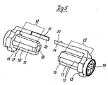
- a continuous coupling rod 9, which is provided with a thread two guide sleeves 10, 11 for the compression spring 6, preferably made of plastic and having essentially the same shape and dimensions, are arranged in opposite directions at a distance.
- the guide sleeves 10, 11 each have an inwardly directed spring guide area 12, 13 on the outer circumference with an end-side contact collar 14, 15.
- the compression spring 6 is arranged between the two contact bundles 14, 15. On the outer circumference of the spring guide area 12, 13 there are alternating longitudinally extending contact surfaces 16 for the spring windings of the compression spring 6 and intermediate non-contact surfaces 17 with a smaller diameter.
- This design enables exact guidance of the compression spring 6 and, due to a reduced contact area, a reduction in the friction occurring between the guide sleeves 10, 11 and the compression spring 6.
- the inner sliding surface of the guide sleeves 10, 11 for the coupling rod 9 is designed as a smooth cylindrical bore 18.
- a plurality of recesses 19, which are distributed in the radial direction and extend in the radial direction, are likewise arranged to reduce the friction of the washers or nuts abutting on the end face.
- the prestressing of the compression spring 6 required for the respective V-belt drive is adjusted via an adjusting nut 7 arranged on the free end region of the coupling rod 9 next to the bracket 8.
- a washer 20 is attached between the adjusting nut 7 and the outer end face of the guide sleeve 10.
- the adjusting nut 7 is turned against a fixed stop 21.
- the stop 21 is located on the opposite side of the coupling rod 9 next to the guide sleeve 11. It consists of two nuts 22, 23 arranged side by side, which bear against a washer 24 at the outer end of the guide sleeve 11.
- the adjusting nut 7 is shown in the setting position with solid lines and in the working position with broken lines.
- the coupling rod 9 is connected to a fork piece 25, on which the short lever arm 27 of a double lever 28 is fastened to a bolt 26.
- the double lever 28 is pivotally mounted on an axis 29.
- the tension roller 4 for the V-belt 3 is rotatably mounted.
- Both guide sleeves 10, 11 are each provided with an inward pointing rod 31, 32, on which markings for the required tension of the compression spring 6 are attached.
- the free ends of the display rods 31, 32 correspond to one another. Their respective position relative to one another indicates the set or the acting tension of the compression spring 6.
- the two display rods 31, 32 run in one plane or parallel to one another.
- the marking area of the display rods 31, 32 is provided with flats 33, 34, which preferably have a semicircular cross section.
- the tension roller 35 is rotatably mounted, which is connected to the V-belt 46.
- the short lever arm 47 of the double lever 41 is connected to a pin 48 of an adjusting ring 49.
- the adjusting ring 49 is arranged on a collar 50 in the outer region of the guide sleeve 11.
- the preload is adjusted via the adjusting nut 7 arranged on the coupling rod 9, which bears directly against the outer end face of the guide sleeve 11 the compression spring 6.
- the tensioning roller 36 is mounted for tensioning the V-belt 52. Since both double levers 40, 41 are connected to the spring holder 5, the tension of the compression spring 6 acts on both tensioning rollers 35, 36 for the V-belts 46, 52.
Landscapes
- Engineering & Computer Science (AREA)
- General Engineering & Computer Science (AREA)
- Mechanical Engineering (AREA)
- Devices For Conveying Motion By Means Of Endless Flexible Members (AREA)
- Friction Gearing (AREA)
- Basic Packing Technique (AREA)
- Harvesting Machines For Specific Crops (AREA)
- Transmissions By Endless Flexible Members (AREA)
Abstract
Description
- Die Erfindung bezieht sich auf eine Spanneinrichtung für einen Zugmitteltrieb, insbesondere für den Antrieb verschiedenartiger Arbeitsvorrichtungen an landwirtschaftlichen Erntemaschinen, nach dem Oberbegriff des Patentanspruchs 1.
- An selbstfahrenden und gezogenen Landmaschinen werden für den Antrieb der einzelnen Funktionsbaugruppen beispielsweise Keilriementriebe verwendet, die eine der Maschinenleistung entsprechende Antriebskraftübertragung gewährleisten müssen. Um dies ständig, und auch unter erschwerten Erntebedingungen zu ermöglichen, ist eine für die jeweilige Leistungsübertragung notwendige Spannung der Keilriemen erforderlich. Dies wird durch eine jedem Keilriementrieb zugeordnete Spanneinrichtung erreicht. Derartige Einrichtungen sind bereits in verschiedenen Ausführungen bekannt.
- So ist beispielsweise in der EP 0 126 808 B1 eine federbelastete Spanneinrichtung mit integrierter Überlastungssicherung für einen Keilriementrieb dargestellt, bei der eine Druckfeder mit einer Vorspanneinrichtung die Spannkraft über eine Zugstange auf einen schwenkbaren Doppelhebel überträgt. Am anderen Ende des Doppelhebels ist eine Spannrolle gelagert, die auf den zu spannenden Keilriemen so einwirkt, dass die für die Antriebskraftübertragung erforderliche Riemenspannung in ausreichendem Maß vorhanden ist. Die Druckfeder ist an einer Federhalterung zwischen Widerlagern an der Zugstange und einer mit dem Maschinenrahmen verbundenen festen Halterung angeordnet. Die jeweils erforderliche Vorspannung der Druckfeder wird durch Drehen der Widerlager an der Zugstange eingestellt. Aufgrund der aufwendigen Ausführung erfordert diese Spanneinrichtung jedoch einen verhältnismäßig hohen Herstellungsaufwand.
- Bei einer weiterhin bekannten Spanneinrichtung besteht die Federhalterung für die Druckfeder im Wesentlichen aus einer an einem Widerlager befestigten Stütz- und Führungshülse, die mit einer Koppelstange schraubbar verbunden ist. Durch Drehen der Stütz- und Führungshülse wird die Spannung der auf ihr angeordneten Druckfeder eingestellt. Die Federspannung wird über die Koppelstange auf einen Doppelhebel übertragen, an dem eine Spannrolle für einen Keilriemen gelagert ist. Das Vorspannen der Druckfeder erfolgt bei gelöster Spannrolle, indem zwischen der Federabstützung und dem Federende hilfsweise lagegesicherte Distanzstücke angebracht werden, die nach der Montage wieder entfernt werden. Die so eingestellte Federspannung wirkt dann auf die Spannrolle des Keilriementriebes ein. Da die für das Vorspannen der Druckfeder notwendigen Arbeiten sehr arbeits- und kraftaufwendig sind und darüber hinaus der Herstellungsaufwand für die erforderlichen Einzelteile hohe Kosten verursacht, ist die Nutzung dieser Vorrichtung mit erheblichen Nachteilen verbunden.
- Der Erfindung liegt die Aufgabe zugrunde, die Federhalterung für die einstellbare Druckfeder so auszuführen, dass sowohl die Herstellungskosten wesentlich,verringert werden als auch die Einstellung für die Vorspannung der Druckfeder vereinfacht und der dafür notwendige Zeit- und Kraftaufwand gesenkt wird.
- Erfindungsgemäß wird diese Aufgabe durch die im Patentanspruch 1 genannten Merkmale gelöst. Weitere vorteilhafte Ausführungen des Erfindungsgegenstandes ergeben sich aus den nachgeordneten Ansprüchen.
- Durch die erfindungsgemäße Ausführung der Spanneinrichtung für einen Keilriementrieb wird mit einem geringen Herstellungs- und Einstellaufwand eine funktionssichere Arbeitsweise der Antriebsvorrichtungen und eine volle Auslastung der Maschinenkapazität der mit einer solchen Einrichtung ausgerüsteten Maschinen erreicht.
- Die Erfindung wird nachstehend an zwei Ausführungsbeispielen näher erläutert. In der zugehörigen Zeichnung zeigen:
- Fig. 1
- die Seitenansicht einer einfach wirkenden Spanneinrichtung für einen Keilriementrieb,
- Fig. 2
- den Schnitt A-A nach Fig. 1,
- Fig. 3
- die Seitenansicht einer doppelt wirkenden Spanneinrichtung für zwei Keilriementriebe,
- Fig. 4
- den Schnitt B-B nach Fig. 3 und
- Fig. 5
- eine perspektivische Darstellung der beiden Führungshülsen für die Druckfeder.
- Der Antrieb verschiedener Funktionsbaugruppen einer in der Zeichnung nicht dargestellten landwirtschaftlichen Erntemaschine erfolgt über mehrere Keilriementriebe, die an den Seitenwänden des Maschinenrahmens angeordnet sind. Zur Gewährleistung einer sicheren Funktionsweise der einzelnen Arbeitsvorrichtungen ist eine zuverlässige und stabile Leistungsübertragung erforderlich. Zu diesem Zweck ist jedem Keilriementrieb eine einfach oder doppelt wirkende Spanneinrichtung zugeordnete, die eine optimale Riemenspannung ermöglicht.
- Bei der in Fig. 1 und 2 dargestellten einfach wirkenden Spanneinrichtung wirkt auf den zwischen zwei Keilriemenscheiben 1,2 verlaufenen Keilriemen 3 eine federbelastete Spannrolle 4 ein. Die jeweils wirkende erforderliche Riemenspannung wird durch eine in einer Federhalterung 5 angeordnete Druckfeder 6 erzeugt, deren Vorspannung über eine Stellmutter 7 einstellbar ist. Die Federhalterung 5 ist an einer mit dem Maschinenrahmen fest verbundenen Konsole 8 befestigt. Auf einer durchgehenden Koppelstange 9, die mit einem Gewinde versehen ist, sind zwei vorzugsweise aus Kunststoff bestehende, im wesentlichen form- und abmessungsgleiche Führungshülsen 10,11 für die Druckfeder 6 mit Abstand gegensinnig angeordnet. Die Führungshülsen 10,11 weisen jeweils am äußeren Umfang einen nach innen gerichteten Federführungsbereich 12,13 mit einem stirnseitigen Anlagebund 14,15 auf. Zwischen den beiden Anlagebunden 14,15 ist die Druckfeder 6 angeordnet. Am äußeren Umfang des Federführungsbereiches 12,13 sind wechselweise in Längsrichtung verlaufende Anlageflächen 16 für die Federwindungen der Druckfeder 6 und dazwischen liegende anlagefreie Flächen 17 mit einem geringeren Durchmesser angeordnet. Diese Ausführung ermöglicht eine exakte Führung der Druckfeder 6 und durch eine verringerte Berührungsfläche eine Reduzierung der zwischen den Führungshülsen 10,11 und der Druckfeder 6 auftretenden Reibung. Die innere Gleitfläche der Führungshülsen 10,11 für die Koppelstange 9 ist als glatte zylindrische Bohrung 18 ausgebildet. Im äußeren Endbereich der Führungshülsen 10,11 sind ebenfalls zur Reibungsminderung der an der stimseitigen Fläche anliegenden Scheiben bzw. Muttern mehrere am inneren Umfang verteilte, in radialer Richtung verlaufende Aussparungen 19 angeordnet. Die Einstellung der für den jeweiligen Keilriementrieb erforderlichen Vorspannung der Druckfeder 6 erfolgt über eine am freien Endbereich der Koppelstange 9 neben der Konsole 8 angeordnete Stellmutter 7. Zwischen der Stellmutter 7 und der äußeren Stirnfläche der Führungshülse 10 ist eine Scheibe 20 angebracht. Beim Spannvorgang wird die Stellmutter 7 gegen einen festen Anschlag 21 gedreht. Der Anschlag 21 befindet sich auf der gegenüberliegenden Seite der Koppelstange 9 neben der Führungshülse 11. Er besteht aus zwei nebeneinander angeordneten Muttern 22,23, die an einer Scheibe 24 am äußeren Ende der Führungshülse 11 anliegen. Nach der erfolgten Einstellung der Vorspannung der Druckfeder 6 und der Montage der Spannrolle 4 wird die Vorspannung durch Zurückdrehen der Stellmutter 7 wieder freigegeben. Die eingestellte Federspannung wirkt nunmehr über die Spannrolle 4 auf den Keilriemen 3 ein.
- In den Fig. 1 bis 4 ist die Stellmutter 7 in der Einstellstellung mit Volllinien und in der Arbeitsstellung mit unterbrochenen Linien dargestellt. An der Anschlagseite ist die Koppelstange 9 mit einem Gabelstück 25 verbunden, an dem an einem Bolzen 26 der kurze Hebelarm 27 eines Doppelhebels 28 befestigt ist. Der Doppelhebel 28 ist an einer Achse 29 schwenkbar gelagert. Am freien Ende des langen Hebelarmes 30 ist die Spannrolle 4 für den Keilriemen 3 drehbar gelagert. Beide Führungshülsen 10,11 sind mit je einem nach innen gerichteten Anzeigestab 31,32 versehen, auf denen Markierungen für die erforderliche Spannung der Druckfeder 6 angebracht sind. Die freien Enden der Anzeigestäbe 31,32 korrespondieren miteinander. Ihre jeweilige Lage zueinander zeigt die eingestellte bzw. die wirkende Spannung der Druckfeder 6 an. Die beiden Anzeigestäbe 31,32 verlaufen je nach Einstellung in einer Ebene oder parallel zueinander. Der Markierungsbereich der Anzeigestäbe 31,32 ist mit Abflachungen 33,34 versehen, die vorzugsweise einen halbkreisförmigen Querschnitt aufweisen.
- Bei der in den Fig. 1 und 2 dargestellten doppelt wirkenden Spanneinrichtung werden zwei Spannrollen 35,36 für zwei Keilriementriebe gemeinsam betätigt. Die Federhalterung 5 für die einstellbare Druckfeder 6 ist dazu oberhalb einer Doppelkeilriemenscheibe 37 angeordnet. Beiderseits der Doppelkeilriemenscheibe 37 sind am Maschinenrahmen Konsolen 38,39 befestigt, an denen je ein Doppelhebel 40,41 an Schwenkachsen 42,43 gelagert ist. Der kurze Hebelarm 44 des Doppelhebels 40 ist mit dem Gabelstück 25 der Federhalterung 5 verbunden. An das Gabelstück 25 schließt sich die Koppelstange 9 an, auf der die beiden Führungshülsen 10,11 für die Druckfeder 6 angeordnet sind. Am freien Ende des langen Hebelarmes 45 ist die Spannrolle 35 drehbar gelagert, die mit dem Keilriemen 46 in Verbindung steht. An der Einstellseite der Federhalterung 5 ist der kurze Hebelarm 47 des Doppelhebels 41 mit einem Zapfen 48 eines Stellringes 49 verbunden. Der Stellring 49 ist auf einem Bund 50 im äußeren Bereich der Führungshülse 11 angeordnet. Über die auf der Koppelstange 9 angeordnete Stellmutter 7, die direkt an der äußeren Stirnfläche der Führungshülse 11 anliegt, erfolgt die Einstellung der Vorspannung der Druckfeder 6. Am langen Hebelarm 51 des Doppelhebels 41 ist für die Spannung des Keilriemens 52 die Spannrolle 36 gelagert. Da beide Doppelhebel 40,41 mit der Federhalterung 5 in Verbindung stehen, wirkt die Spannung der Druckfeder 6 auf beide Spannrollen 35,36 für die Keilriemen 46,52 ein.
- Der Aufbau und die Funktionsweise der doppelt wirkenden Spanneinrichtung stimmt im wesentlichen mit der bereits beschriebenen einfach wirkenden Ausführung überein.
- Vorstehend wurde der Erfindungsgegenstand beispielsweise bei einem Keilriemenantrieb beschrieben, er ist jedoch für jede Art von Zugmitteltrieben erfindungsgemäß verwendbar.
-
- 1
- Keilriemenscheibe
- 2
- Keilriemenscheibe
- 3
- Keilriemen
- 4
- Spannrolle
- 5
- Federhalterung
- 6
- Druckfeder
- 7
- Stellmutter
- 8
- Konsole
- 9
- Koppelstange
- 10,11
- Führungshülsen
- 12,13
- Federführungsbereich
- 14,15
- Anlagebund
- 16
- Anlageflächen
- 17
- anlagefreie Flächen
- 18
- Bohrung
- 19
- Aussparungen
- 20
- Scheibe
- 21
- Anschlag
- 22,23
- Muttern
- 24
- Scheibe
- 25
- Gabelstück
- 26
- Bolzen
- 27
- kurzer Hebelarm
- 28
- Doppelhebel
- 29
- Achse
- 30
- Langer Hebelarm
- 31,32
- Anzeigestab
- 33,34
- Abflachungen
- 35,36
- Spannrollen
- 37
- Doppelkeilriemenscheibe
- 38,39
- Konsole
- 40,41
- Doppelhebel
- 42,43
- Schwenkachsen
- 44
- kurzer Hebelarm
- 45
- langer Hebelarm
- 46
- Keilriemen
- 47
- kurzer Hebelarm
- 48
- Zapfen
- 49
- Stellring
- 50
- Bund
- 51
- langer Hebelarm
- 52
- Keilriemen
Claims (7)
- Spanneinrichtung für einen Zugmitteltrieb, insbesondere für den Antrieb verschiedenartiger Arbeitsvorrichtungen an landwirtschaftlichen Erntemaschinen, bestehend aus einer Federhalterung für eine lagegeführte und einstellbare Druckfeder, wobei deren Federspannung über eine Koppelstange direkt, oder über einen zusätzlichen Hebel indirekt, mittels einer Spannrolle auf ein zu spannendes Zugmittel übertragbar ist,
dadurch gekennzeichnet,
dass auf einer durchgehenden Koppelstange (9) zwei gleichartige Führungshülsen (10,11) mit einer dazwischen liegenden Druckfeder (6) mit Abstand gegensinnig angeordnet sind. - Spanneinrichtung nach Anspruch 1,
dadurch gekennzeichnet,
dass die Führungshülsen (10,11) vorzugsweise aus Kunststoff bestehen. - Spanneinrichtung nach Anspruch 1 und 2,
dadurch gekennzeichnet,
dass die Führungshülsen (10,11) jeweils am äußeren Umfang einen nach innen gerichteten Federführungsbereich (12,13) mit einem stirnseitigen Anlagebund (14,15) aufweisen. - Spanneinrichtung nach den Ansprüchen 1 bis 3,
dadurch gekennzeichnet,
dass am Umfang des Federführungsbereiches (12,13) der Führungshülsen (10,11) wechselweise in Längsrichtung verlaufende Anlageflächen (16) für die Federwindungen der Druckfeder (6) mit dazwischen liegenden anlagefreien Flächen (17) angeordnet sind. - Spanneinrichtung nach den Ansprüchen 1 bis 4,
dadurch gekennzeichnet,
dass im äußeren Endbereich der Führungshülsen (10,11) mehrere am inneren Umfang verteilte, in radialer Richtung verlaufende Aussparungen (19) angeordnet sind - Spanneinrichtung nach den Ansprüchen 1 bis 5,
dadurch gekennzeichnet,
dass nach erfolgter Einstellung der Vorspannung der Druckfeder (6) und der Montage der Spannrollen (2,35,36) die Vorspannung durch Zurückdrehen der Stellmutter (7) wieder freigebbar ist. - Spanneinrichtung nach den Ansprüchen 1 bis 5,
dadurch gekennzeichnet,
dass beide Führungshülsen (10,11) mit zumindest je einem nach innen gerichteten Anzeigestab (31,32) versehen ist.
Applications Claiming Priority (2)
| Application Number | Priority Date | Filing Date | Title |
|---|---|---|---|
| DE10312321A DE10312321A1 (de) | 2003-03-19 | 2003-03-19 | Spanneinrichtung für einen Zugmitteltrieb |
| DE10312321 | 2003-03-19 |
Publications (3)
| Publication Number | Publication Date |
|---|---|
| EP1460307A2 true EP1460307A2 (de) | 2004-09-22 |
| EP1460307A3 EP1460307A3 (de) | 2006-04-19 |
| EP1460307B1 EP1460307B1 (de) | 2008-01-09 |
Family
ID=32797984
Family Applications (1)
| Application Number | Title | Priority Date | Filing Date |
|---|---|---|---|
| EP04005064A Expired - Lifetime EP1460307B1 (de) | 2003-03-19 | 2004-03-04 | Spanneinrichtung für einen Zugmitteltrieb |
Country Status (3)
| Country | Link |
|---|---|
| EP (1) | EP1460307B1 (de) |
| AT (1) | ATE383528T1 (de) |
| DE (2) | DE10312321A1 (de) |
Cited By (13)
| Publication number | Priority date | Publication date | Assignee | Title |
|---|---|---|---|---|
| DE102004058770A1 (de) * | 2004-12-07 | 2006-06-08 | Schaeffler Kg | Spannvorrichtung für einen Zugmitteltrieb |
| EP2080932A3 (de) * | 2008-01-16 | 2010-12-15 | Bayerische Motoren Werke Aktiengesellschaft | Zugmittelspanneinrichtung |
| CN106763587A (zh) * | 2016-12-30 | 2017-05-31 | 广西玉柴机器股份有限公司 | 发电机的固定式张紧器组件 |
| CN107269784A (zh) * | 2017-08-04 | 2017-10-20 | 陕西中烟工业有限责任公司 | 一种三角带预紧装置及其使用方法 |
| CN108179976A (zh) * | 2017-12-27 | 2018-06-19 | 中国石油集团川庆钻探工程有限公司长庆钻井总公司 | 一种可调预紧力式扭矩调节器及调节方法 |
| CN108506436A (zh) * | 2018-06-04 | 2018-09-07 | 东风井关农业机械有限公司 | 一种大幅度的皮带张紧工装 |
| CN112079057A (zh) * | 2020-10-21 | 2020-12-15 | 张家港市兰航机械有限公司 | 收卷装置的皮带张紧结构 |
| CN112539257A (zh) * | 2020-11-24 | 2021-03-23 | 广州载德自动化智能科技有限公司 | 传动条的张紧结构 |
| CN113805001A (zh) * | 2021-09-09 | 2021-12-17 | 湖南电科院检测集团有限公司 | 一种具有保护措施的高压产品试验装置 |
| WO2022061457A1 (en) | 2020-09-22 | 2022-03-31 | 1783590 Ontario Inc. D/B/A Inmotive Inc. | Transmission |
| CN114673766A (zh) * | 2022-04-11 | 2022-06-28 | 大庆丹诺石油科技开发有限公司 | 一种具有远程传输及智能调节抽油机皮带张紧力的保护装置 |
| CN117918542A (zh) * | 2022-10-13 | 2024-04-26 | 青岛维泰科设备有限公司 | 一种洋葱去皮机 |
| EP4446615A1 (de) * | 2023-04-12 | 2024-10-16 | CLAAS Selbstfahrende Erntemaschinen GmbH | Riemengetriebe |
Families Citing this family (3)
| Publication number | Priority date | Publication date | Assignee | Title |
|---|---|---|---|---|
| DE102012101807A1 (de) | 2012-03-05 | 2013-09-05 | Claas Selbstfahrende Erntemaschinen Gmbh | Selbstfahrende Erntemaschine |
| DE102017220945A1 (de) * | 2017-11-23 | 2019-05-23 | Continental Teves Ag & Co. Ohg | Einheit, bestehend aus einem Getriebe und einer Bremse, und elektromotorisch angetriebenes Fahrzeug mit einer solchen Einheit |
| DE102024122298A1 (de) | 2024-08-05 | 2026-02-05 | Claas Selbstfahrende Erntemaschinen Gmbh | Landwirtschaftliche Arbeitsmaschine |
Citations (1)
| Publication number | Priority date | Publication date | Assignee | Title |
|---|---|---|---|---|
| EP0126808B1 (de) | 1983-05-27 | 1988-08-10 | Ford New Holland N.V. | Riemenkraftübertragungsvorrichtung mit Riemenspanngerät |
Family Cites Families (11)
| Publication number | Priority date | Publication date | Assignee | Title |
|---|---|---|---|---|
| US1615544A (en) * | 1923-10-04 | 1927-01-25 | Safety Car Heating & Lighting | Power transmission |
| US2663195A (en) * | 1950-06-20 | 1953-12-22 | Eaton Mfg Co | Belt tensioner |
| DE871391C (de) * | 1951-04-28 | 1953-03-23 | Hans Weber | Einstell-, Anzeige- und Kontrollvorrichtung fuer richtige Achsspannung von Kraftuebertragungselementen |
| CH329746A (fr) * | 1956-04-16 | 1958-05-15 | Bobst Fils Sa J | Presse travaillant une matière en feuilles transportées par une paire de chaînes sans fin |
| DE3108688A1 (de) * | 1981-03-07 | 1982-09-23 | Erwin 5883 Kierspe Umlauf | Federanordnung |
| JPS6275165A (ja) * | 1985-09-27 | 1987-04-07 | Toyoda Autom Loom Works Ltd | オルタネ−タ駆動用ベルトの張力調整装置 |
| FR2644541B1 (fr) * | 1989-03-17 | 1994-07-01 | Hutchinson | Tendeur pour courroie de transmission de puissance |
| FR2660724B2 (fr) * | 1989-07-06 | 1994-10-28 | Hutchinson | Tendeur pour courroie de transmission. |
| DE4021314A1 (de) * | 1989-11-02 | 1991-05-08 | Bilstein August Gmbh Co Kg | Federbein fuer ein kraftfahrzeug |
| DE19501685C1 (de) * | 1995-01-20 | 1996-07-04 | Litens Automotive Gmbh | Riemenspanner |
| DE19504961C2 (de) * | 1995-02-15 | 1999-03-18 | Scherdel Datec Datentechnik Fo | Federstütze |
-
2003
- 2003-03-19 DE DE10312321A patent/DE10312321A1/de not_active Withdrawn
-
2004
- 2004-03-04 DE DE502004005879T patent/DE502004005879D1/de not_active Expired - Lifetime
- 2004-03-04 AT AT04005064T patent/ATE383528T1/de not_active IP Right Cessation
- 2004-03-04 EP EP04005064A patent/EP1460307B1/de not_active Expired - Lifetime
Patent Citations (1)
| Publication number | Priority date | Publication date | Assignee | Title |
|---|---|---|---|---|
| EP0126808B1 (de) | 1983-05-27 | 1988-08-10 | Ford New Holland N.V. | Riemenkraftübertragungsvorrichtung mit Riemenspanngerät |
Cited By (16)
| Publication number | Priority date | Publication date | Assignee | Title |
|---|---|---|---|---|
| DE102004058770A1 (de) * | 2004-12-07 | 2006-06-08 | Schaeffler Kg | Spannvorrichtung für einen Zugmitteltrieb |
| EP2080932A3 (de) * | 2008-01-16 | 2010-12-15 | Bayerische Motoren Werke Aktiengesellschaft | Zugmittelspanneinrichtung |
| CN106763587A (zh) * | 2016-12-30 | 2017-05-31 | 广西玉柴机器股份有限公司 | 发电机的固定式张紧器组件 |
| CN107269784A (zh) * | 2017-08-04 | 2017-10-20 | 陕西中烟工业有限责任公司 | 一种三角带预紧装置及其使用方法 |
| CN108179976A (zh) * | 2017-12-27 | 2018-06-19 | 中国石油集团川庆钻探工程有限公司长庆钻井总公司 | 一种可调预紧力式扭矩调节器及调节方法 |
| CN108506436A (zh) * | 2018-06-04 | 2018-09-07 | 东风井关农业机械有限公司 | 一种大幅度的皮带张紧工装 |
| EP4217624A4 (de) * | 2020-09-22 | 2024-07-24 | 1783590 Ontario Inc. d/b/a Inmotive Inc. | Übertragung |
| WO2022061457A1 (en) | 2020-09-22 | 2022-03-31 | 1783590 Ontario Inc. D/B/A Inmotive Inc. | Transmission |
| US12270471B2 (en) | 2020-09-22 | 2025-04-08 | 1783590 Ontario Inc. | Transmission |
| EP4217624A1 (de) | 2020-09-22 | 2023-08-02 | 1783590 Ontario Inc. d/b/a Inmotive Inc. | Übertragung |
| CN112079057A (zh) * | 2020-10-21 | 2020-12-15 | 张家港市兰航机械有限公司 | 收卷装置的皮带张紧结构 |
| CN112539257A (zh) * | 2020-11-24 | 2021-03-23 | 广州载德自动化智能科技有限公司 | 传动条的张紧结构 |
| CN113805001A (zh) * | 2021-09-09 | 2021-12-17 | 湖南电科院检测集团有限公司 | 一种具有保护措施的高压产品试验装置 |
| CN114673766A (zh) * | 2022-04-11 | 2022-06-28 | 大庆丹诺石油科技开发有限公司 | 一种具有远程传输及智能调节抽油机皮带张紧力的保护装置 |
| CN117918542A (zh) * | 2022-10-13 | 2024-04-26 | 青岛维泰科设备有限公司 | 一种洋葱去皮机 |
| EP4446615A1 (de) * | 2023-04-12 | 2024-10-16 | CLAAS Selbstfahrende Erntemaschinen GmbH | Riemengetriebe |
Also Published As
| Publication number | Publication date |
|---|---|
| ATE383528T1 (de) | 2008-01-15 |
| DE502004005879D1 (de) | 2008-02-21 |
| DE10312321A1 (de) | 2004-09-30 |
| EP1460307B1 (de) | 2008-01-09 |
| EP1460307A3 (de) | 2006-04-19 |
Similar Documents
| Publication | Publication Date | Title |
|---|---|---|
| EP1460307B1 (de) | Spanneinrichtung für einen Zugmitteltrieb | |
| DE8200481U1 (de) | Riemenspannvorrichtung fuer einen von einem motor angetriebenen treibriemen fuer hilfsaggregate von kraftfahrzeugen | |
| EP3053684A1 (de) | Trennvorrichtung zum trennen eines zylindrischen werkstücks | |
| EP2163496B1 (de) | Rollenförderer mit gesonderter Antriebsbaugruppe | |
| AT413692B (de) | Zugmitteltrieb, insbesondere für eine fördereinrichtung | |
| EP2843261B1 (de) | Zugmittelspanner, Vibrationsschweißanlage mit Zugmittelspanner sowie Herstellungsverfahren eines Zugmittelspanners | |
| DE1952478C3 (de) | Automatische Riemenspannvorrichtung für ein stufenlos einstellbares Keilriemengetriebe | |
| DE3912944A1 (de) | Riemenspannvorrichtung | |
| DE102020202926B4 (de) | Gurtförderer für einen Förderwagen eines Quergurtsorters | |
| DE4413422C1 (de) | Transportable Antriebsanordnung | |
| DE102007008124A1 (de) | Seilsägesystem für den Natursteinbereich | |
| DE4127714A1 (de) | Einrichtung zum befestigen und spannen eines drucktuches auf einem zylinder einer druckmaschine | |
| DE102017121641B4 (de) | Riemenspanner für Längsförderer | |
| EP1996490B1 (de) | Spannvorrichtung eines umlaufenden elementes | |
| EP3385207A1 (de) | Spindel für einen wickler | |
| DE19720861C2 (de) | Vorrichtung zum Dehnungsausgleich eines Antriebsmittels eines linear bewegten Wagens oder Schlittens | |
| EP2695799B1 (de) | Pendel-/knickgelenkte Baumaschine | |
| DE102015119935A1 (de) | Doppelriemenspanner, Riementrieb und Kraftfahrzeug | |
| DE69205637T2 (de) | Spannvorrichtung für Treibriemen. | |
| DE4130273C2 (de) | ||
| DE10223721B4 (de) | Straßenfertiger mit einer Bohle und Spannelemente dafür | |
| DE20210626U1 (de) | Bandfördereinrichtung | |
| DE3512594C1 (de) | Spannvorrichtung für einen Kratzboden von Transportfahrzeugen | |
| DE102006050569B3 (de) | Vorrichtung zum Umgang mit zylindrischen Großteilen, insbesondere zum Umgang mit Druckzylindern von Rollenoffestdruckmaschinen | |
| WO2016101950A1 (de) | Anordnung zum aufspannen eines sattelbauteils auf ein rohr |
Legal Events
| Date | Code | Title | Description |
|---|---|---|---|
| PUAI | Public reference made under article 153(3) epc to a published international application that has entered the european phase |
Free format text: ORIGINAL CODE: 0009012 |
|
| AK | Designated contracting states |
Kind code of ref document: A2 Designated state(s): AT BE BG CH CY CZ DE DK EE ES FI FR GB GR HU IE IT LI LU MC NL PL PT RO SE SI SK TR |
|
| AX | Request for extension of the european patent |
Extension state: AL LT LV MK |
|
| PUAL | Search report despatched |
Free format text: ORIGINAL CODE: 0009013 |
|
| AK | Designated contracting states |
Kind code of ref document: A3 Designated state(s): AT BE BG CH CY CZ DE DK EE ES FI FR GB GR HU IE IT LI LU MC NL PL PT RO SE SI SK TR |
|
| AX | Request for extension of the european patent |
Extension state: AL LT LV MK |
|
| 17P | Request for examination filed |
Effective date: 20061019 |
|
| AKX | Designation fees paid |
Designated state(s): AT BE BG CH CY CZ DE DK EE ES FI FR GB GR HU IE IT LI LU MC NL PL PT RO SE SI SK TR |
|
| 17Q | First examination report despatched |
Effective date: 20061222 |
|
| GRAP | Despatch of communication of intention to grant a patent |
Free format text: ORIGINAL CODE: EPIDOSNIGR1 |
|
| GRAS | Grant fee paid |
Free format text: ORIGINAL CODE: EPIDOSNIGR3 |
|
| GRAA | (expected) grant |
Free format text: ORIGINAL CODE: 0009210 |
|
| AK | Designated contracting states |
Kind code of ref document: B1 Designated state(s): AT BE BG CH CY CZ DE DK EE ES FI FR GB GR HU IE IT LI LU MC NL PL PT RO SE SI SK TR |
|
| REG | Reference to a national code |
Ref country code: GB Ref legal event code: FG4D Free format text: NOT ENGLISH |
|
| REG | Reference to a national code |
Ref country code: CH Ref legal event code: EP |
|
| REG | Reference to a national code |
Ref country code: IE Ref legal event code: FG4D Free format text: LANGUAGE OF EP DOCUMENT: GERMAN |
|
| REF | Corresponds to: |
Ref document number: 502004005879 Country of ref document: DE Date of ref document: 20080221 Kind code of ref document: P |
|
| REG | Reference to a national code |
Ref country code: DE Ref legal event code: R096 Ref document number: 502004005879 Country of ref document: DE Effective date: 20080221 |
|
| PG25 | Lapsed in a contracting state [announced via postgrant information from national office to epo] |
Ref country code: NL Free format text: LAPSE BECAUSE OF FAILURE TO SUBMIT A TRANSLATION OF THE DESCRIPTION OR TO PAY THE FEE WITHIN THE PRESCRIBED TIME-LIMIT Effective date: 20080109 Ref country code: SI Free format text: LAPSE BECAUSE OF FAILURE TO SUBMIT A TRANSLATION OF THE DESCRIPTION OR TO PAY THE FEE WITHIN THE PRESCRIBED TIME-LIMIT Effective date: 20080109 |
|
| NLV1 | Nl: lapsed or annulled due to failure to fulfill the requirements of art. 29p and 29m of the patents act | ||
| PG25 | Lapsed in a contracting state [announced via postgrant information from national office to epo] |
Ref country code: FI Free format text: LAPSE BECAUSE OF FAILURE TO SUBMIT A TRANSLATION OF THE DESCRIPTION OR TO PAY THE FEE WITHIN THE PRESCRIBED TIME-LIMIT Effective date: 20080109 Ref country code: ES Free format text: LAPSE BECAUSE OF FAILURE TO SUBMIT A TRANSLATION OF THE DESCRIPTION OR TO PAY THE FEE WITHIN THE PRESCRIBED TIME-LIMIT Effective date: 20080420 |
|
| ET | Fr: translation filed | ||
| PG25 | Lapsed in a contracting state [announced via postgrant information from national office to epo] |
Ref country code: BG Free format text: LAPSE BECAUSE OF FAILURE TO SUBMIT A TRANSLATION OF THE DESCRIPTION OR TO PAY THE FEE WITHIN THE PRESCRIBED TIME-LIMIT Effective date: 20080409 |
|
| PG25 | Lapsed in a contracting state [announced via postgrant information from national office to epo] |
Ref country code: PT Free format text: LAPSE BECAUSE OF FAILURE TO SUBMIT A TRANSLATION OF THE DESCRIPTION OR TO PAY THE FEE WITHIN THE PRESCRIBED TIME-LIMIT Effective date: 20080609 Ref country code: PL Free format text: LAPSE BECAUSE OF FAILURE TO SUBMIT A TRANSLATION OF THE DESCRIPTION OR TO PAY THE FEE WITHIN THE PRESCRIBED TIME-LIMIT Effective date: 20080109 |
|
| REG | Reference to a national code |
Ref country code: IE Ref legal event code: FD4D |
|
| PG25 | Lapsed in a contracting state [announced via postgrant information from national office to epo] |
Ref country code: CZ Free format text: LAPSE BECAUSE OF FAILURE TO SUBMIT A TRANSLATION OF THE DESCRIPTION OR TO PAY THE FEE WITHIN THE PRESCRIBED TIME-LIMIT Effective date: 20080109 Ref country code: DK Free format text: LAPSE BECAUSE OF FAILURE TO SUBMIT A TRANSLATION OF THE DESCRIPTION OR TO PAY THE FEE WITHIN THE PRESCRIBED TIME-LIMIT Effective date: 20080109 Ref country code: SE Free format text: LAPSE BECAUSE OF FAILURE TO SUBMIT A TRANSLATION OF THE DESCRIPTION OR TO PAY THE FEE WITHIN THE PRESCRIBED TIME-LIMIT Effective date: 20080409 Ref country code: IE Free format text: LAPSE BECAUSE OF FAILURE TO SUBMIT A TRANSLATION OF THE DESCRIPTION OR TO PAY THE FEE WITHIN THE PRESCRIBED TIME-LIMIT Effective date: 20080109 Ref country code: MC Free format text: LAPSE BECAUSE OF NON-PAYMENT OF DUE FEES Effective date: 20080331 Ref country code: SK Free format text: LAPSE BECAUSE OF FAILURE TO SUBMIT A TRANSLATION OF THE DESCRIPTION OR TO PAY THE FEE WITHIN THE PRESCRIBED TIME-LIMIT Effective date: 20080109 |
|
| REG | Reference to a national code |
Ref country code: CH Ref legal event code: PL |
|
| PLBE | No opposition filed within time limit |
Free format text: ORIGINAL CODE: 0009261 |
|
| STAA | Information on the status of an ep patent application or granted ep patent |
Free format text: STATUS: NO OPPOSITION FILED WITHIN TIME LIMIT |
|
| PG25 | Lapsed in a contracting state [announced via postgrant information from national office to epo] |
Ref country code: RO Free format text: LAPSE BECAUSE OF FAILURE TO SUBMIT A TRANSLATION OF THE DESCRIPTION OR TO PAY THE FEE WITHIN THE PRESCRIBED TIME-LIMIT Effective date: 20080109 |
|
| 26N | No opposition filed |
Effective date: 20081010 |
|
| REG | Reference to a national code |
Ref country code: DE Ref legal event code: R097 Ref document number: 502004005879 Country of ref document: DE Effective date: 20081010 |
|
| PG25 | Lapsed in a contracting state [announced via postgrant information from national office to epo] |
Ref country code: EE Free format text: LAPSE BECAUSE OF FAILURE TO SUBMIT A TRANSLATION OF THE DESCRIPTION OR TO PAY THE FEE WITHIN THE PRESCRIBED TIME-LIMIT Effective date: 20080109 Ref country code: CH Free format text: LAPSE BECAUSE OF NON-PAYMENT OF DUE FEES Effective date: 20080331 Ref country code: LI Free format text: LAPSE BECAUSE OF NON-PAYMENT OF DUE FEES Effective date: 20080331 |
|
| PG25 | Lapsed in a contracting state [announced via postgrant information from national office to epo] |
Ref country code: CY Free format text: LAPSE BECAUSE OF FAILURE TO SUBMIT A TRANSLATION OF THE DESCRIPTION OR TO PAY THE FEE WITHIN THE PRESCRIBED TIME-LIMIT Effective date: 20080109 |
|
| PG25 | Lapsed in a contracting state [announced via postgrant information from national office to epo] |
Ref country code: IT Free format text: LAPSE BECAUSE OF FAILURE TO SUBMIT A TRANSLATION OF THE DESCRIPTION OR TO PAY THE FEE WITHIN THE PRESCRIBED TIME-LIMIT Effective date: 20080109 Ref country code: AT Free format text: LAPSE BECAUSE OF NON-PAYMENT OF DUE FEES Effective date: 20080304 |
|
| PG25 | Lapsed in a contracting state [announced via postgrant information from national office to epo] |
Ref country code: HU Free format text: LAPSE BECAUSE OF FAILURE TO SUBMIT A TRANSLATION OF THE DESCRIPTION OR TO PAY THE FEE WITHIN THE PRESCRIBED TIME-LIMIT Effective date: 20080710 Ref country code: LU Free format text: LAPSE BECAUSE OF NON-PAYMENT OF DUE FEES Effective date: 20080304 |
|
| PG25 | Lapsed in a contracting state [announced via postgrant information from national office to epo] |
Ref country code: TR Free format text: LAPSE BECAUSE OF FAILURE TO SUBMIT A TRANSLATION OF THE DESCRIPTION OR TO PAY THE FEE WITHIN THE PRESCRIBED TIME-LIMIT Effective date: 20080109 |
|
| PG25 | Lapsed in a contracting state [announced via postgrant information from national office to epo] |
Ref country code: GR Free format text: LAPSE BECAUSE OF FAILURE TO SUBMIT A TRANSLATION OF THE DESCRIPTION OR TO PAY THE FEE WITHIN THE PRESCRIBED TIME-LIMIT Effective date: 20080410 |
|
| REG | Reference to a national code |
Ref country code: FR Ref legal event code: PLFP Year of fee payment: 13 |
|
| REG | Reference to a national code |
Ref country code: FR Ref legal event code: PLFP Year of fee payment: 14 |
|
| REG | Reference to a national code |
Ref country code: DE Ref legal event code: R084 Ref document number: 502004005879 Country of ref document: DE |
|
| REG | Reference to a national code |
Ref country code: FR Ref legal event code: PLFP Year of fee payment: 15 |
|
| PGFP | Annual fee paid to national office [announced via postgrant information from national office to epo] |
Ref country code: GB Payment date: 20200323 Year of fee payment: 17 |
|
| GBPC | Gb: european patent ceased through non-payment of renewal fee |
Effective date: 20210304 |
|
| PG25 | Lapsed in a contracting state [announced via postgrant information from national office to epo] |
Ref country code: GB Free format text: LAPSE BECAUSE OF NON-PAYMENT OF DUE FEES Effective date: 20210304 |
|
| PGFP | Annual fee paid to national office [announced via postgrant information from national office to epo] |
Ref country code: FR Payment date: 20230321 Year of fee payment: 20 |
|
| PGFP | Annual fee paid to national office [announced via postgrant information from national office to epo] |
Ref country code: DE Payment date: 20230321 Year of fee payment: 20 Ref country code: BE Payment date: 20230321 Year of fee payment: 20 |
|
| P01 | Opt-out of the competence of the unified patent court (upc) registered |
Effective date: 20230512 |
|
| REG | Reference to a national code |
Ref country code: DE Ref legal event code: R071 Ref document number: 502004005879 Country of ref document: DE |
|
| REG | Reference to a national code |
Ref country code: BE Ref legal event code: MK Effective date: 20240304 |