EP1460331B1 - Alimentation en énergie d'un terminal gazier à partir d'un navire transportant du gaz liquéfié - Google Patents
Alimentation en énergie d'un terminal gazier à partir d'un navire transportant du gaz liquéfié Download PDFInfo
- Publication number
- EP1460331B1 EP1460331B1 EP20040290682 EP04290682A EP1460331B1 EP 1460331 B1 EP1460331 B1 EP 1460331B1 EP 20040290682 EP20040290682 EP 20040290682 EP 04290682 A EP04290682 A EP 04290682A EP 1460331 B1 EP1460331 B1 EP 1460331B1
- Authority
- EP
- European Patent Office
- Prior art keywords
- gas
- ship
- terminal
- heat
- water
- Prior art date
- Legal status (The legal status is an assumption and is not a legal conclusion. Google has not performed a legal analysis and makes no representation as to the accuracy of the status listed.)
- Expired - Lifetime
Links
- 238000000034 method Methods 0.000 claims abstract description 26
- 230000005611 electricity Effects 0.000 claims abstract description 14
- 239000007789 gas Substances 0.000 claims description 208
- XLYOFNOQVPJJNP-UHFFFAOYSA-N water Substances O XLYOFNOQVPJJNP-UHFFFAOYSA-N 0.000 claims description 59
- 239000013529 heat transfer fluid Substances 0.000 claims description 21
- 238000001816 cooling Methods 0.000 claims description 12
- 238000002309 gasification Methods 0.000 claims description 12
- 239000013535 sea water Substances 0.000 claims description 12
- 238000011084 recovery Methods 0.000 claims description 9
- 239000013505 freshwater Substances 0.000 claims description 8
- 239000003949 liquefied natural gas Substances 0.000 claims description 5
- 238000009434 installation Methods 0.000 claims description 2
- 239000003915 liquefied petroleum gas Substances 0.000 claims description 2
- 239000012809 cooling fluid Substances 0.000 claims 1
- 238000010438 heat treatment Methods 0.000 claims 1
- VNWKTOKETHGBQD-UHFFFAOYSA-N methane Chemical compound C VNWKTOKETHGBQD-UHFFFAOYSA-N 0.000 description 14
- 239000012530 fluid Substances 0.000 description 8
- 239000003345 natural gas Substances 0.000 description 7
- 230000008901 benefit Effects 0.000 description 4
- 239000002826 coolant Substances 0.000 description 4
- 238000005260 corrosion Methods 0.000 description 2
- 230000007797 corrosion Effects 0.000 description 2
- 238000010586 diagram Methods 0.000 description 2
- 239000003208 petroleum Substances 0.000 description 2
- 230000015556 catabolic process Effects 0.000 description 1
- 230000008878 coupling Effects 0.000 description 1
- 238000010168 coupling process Methods 0.000 description 1
- 238000005859 coupling reaction Methods 0.000 description 1
- 238000006731 degradation reaction Methods 0.000 description 1
- 238000007599 discharging Methods 0.000 description 1
- 238000001704 evaporation Methods 0.000 description 1
- 230000008020 evaporation Effects 0.000 description 1
- 239000000446 fuel Substances 0.000 description 1
- 238000002347 injection Methods 0.000 description 1
- 239000007924 injection Substances 0.000 description 1
- 238000003973 irrigation Methods 0.000 description 1
- 230000002262 irrigation Effects 0.000 description 1
- 239000007788 liquid Substances 0.000 description 1
- 238000012423 maintenance Methods 0.000 description 1
- 238000013021 overheating Methods 0.000 description 1
- 238000005070 sampling Methods 0.000 description 1
- 239000000243 solution Substances 0.000 description 1
- 239000006200 vaporizer Substances 0.000 description 1
- 239000002699 waste material Substances 0.000 description 1
Images


Classifications
-
- B—PERFORMING OPERATIONS; TRANSPORTING
- B63—SHIPS OR OTHER WATERBORNE VESSELS; RELATED EQUIPMENT
- B63B—SHIPS OR OTHER WATERBORNE VESSELS; EQUIPMENT FOR SHIPPING
- B63B25/00—Load-accommodating arrangements, e.g. stowing, trimming; Vessels characterised thereby
- B63B25/02—Load-accommodating arrangements, e.g. stowing, trimming; Vessels characterised thereby for bulk goods
- B63B25/08—Load-accommodating arrangements, e.g. stowing, trimming; Vessels characterised thereby for bulk goods fluid
-
- F—MECHANICAL ENGINEERING; LIGHTING; HEATING; WEAPONS; BLASTING
- F17—STORING OR DISTRIBUTING GASES OR LIQUIDS
- F17C—VESSELS FOR CONTAINING OR STORING COMPRESSED, LIQUEFIED OR SOLIDIFIED GASES; FIXED-CAPACITY GAS-HOLDERS; FILLING VESSELS WITH, OR DISCHARGING FROM VESSELS, COMPRESSED, LIQUEFIED, OR SOLIDIFIED GASES
- F17C9/00—Methods or apparatus for discharging liquefied or solidified gases from vessels not under pressure
- F17C9/02—Methods or apparatus for discharging liquefied or solidified gases from vessels not under pressure with change of state, e.g. vaporisation
- F17C9/04—Recovery of thermal energy
-
- B—PERFORMING OPERATIONS; TRANSPORTING
- B63—SHIPS OR OTHER WATERBORNE VESSELS; RELATED EQUIPMENT
- B63J—AUXILIARIES ON VESSELS
- B63J3/00—Driving of auxiliaries
- B63J3/02—Driving of auxiliaries from propulsion power plant
-
- B—PERFORMING OPERATIONS; TRANSPORTING
- B63—SHIPS OR OTHER WATERBORNE VESSELS; RELATED EQUIPMENT
- B63B—SHIPS OR OTHER WATERBORNE VESSELS; EQUIPMENT FOR SHIPPING
- B63B27/00—Arrangement of ship-based loading or unloading equipment for cargo or passengers
- B63B27/24—Arrangement of ship-based loading or unloading equipment for cargo or passengers of pipe-lines
-
- F—MECHANICAL ENGINEERING; LIGHTING; HEATING; WEAPONS; BLASTING
- F17—STORING OR DISTRIBUTING GASES OR LIQUIDS
- F17C—VESSELS FOR CONTAINING OR STORING COMPRESSED, LIQUEFIED OR SOLIDIFIED GASES; FIXED-CAPACITY GAS-HOLDERS; FILLING VESSELS WITH, OR DISCHARGING FROM VESSELS, COMPRESSED, LIQUEFIED, OR SOLIDIFIED GASES
- F17C2205/00—Vessel construction, in particular mounting arrangements, attachments or identifications means
- F17C2205/03—Fluid connections, filters, valves, closure means or other attachments
- F17C2205/0302—Fittings, valves, filters, or components in connection with the gas storage device
- F17C2205/0323—Valves
-
- F—MECHANICAL ENGINEERING; LIGHTING; HEATING; WEAPONS; BLASTING
- F17—STORING OR DISTRIBUTING GASES OR LIQUIDS
- F17C—VESSELS FOR CONTAINING OR STORING COMPRESSED, LIQUEFIED OR SOLIDIFIED GASES; FIXED-CAPACITY GAS-HOLDERS; FILLING VESSELS WITH, OR DISCHARGING FROM VESSELS, COMPRESSED, LIQUEFIED, OR SOLIDIFIED GASES
- F17C2221/00—Handled fluid, in particular type of fluid
- F17C2221/03—Mixtures
- F17C2221/032—Hydrocarbons
- F17C2221/033—Methane, e.g. natural gas, CNG, LNG, GNL, GNC, PLNG
-
- F—MECHANICAL ENGINEERING; LIGHTING; HEATING; WEAPONS; BLASTING
- F17—STORING OR DISTRIBUTING GASES OR LIQUIDS
- F17C—VESSELS FOR CONTAINING OR STORING COMPRESSED, LIQUEFIED OR SOLIDIFIED GASES; FIXED-CAPACITY GAS-HOLDERS; FILLING VESSELS WITH, OR DISCHARGING FROM VESSELS, COMPRESSED, LIQUEFIED, OR SOLIDIFIED GASES
- F17C2221/00—Handled fluid, in particular type of fluid
- F17C2221/03—Mixtures
- F17C2221/032—Hydrocarbons
- F17C2221/035—Propane butane, e.g. LPG, GPL
-
- F—MECHANICAL ENGINEERING; LIGHTING; HEATING; WEAPONS; BLASTING
- F17—STORING OR DISTRIBUTING GASES OR LIQUIDS
- F17C—VESSELS FOR CONTAINING OR STORING COMPRESSED, LIQUEFIED OR SOLIDIFIED GASES; FIXED-CAPACITY GAS-HOLDERS; FILLING VESSELS WITH, OR DISCHARGING FROM VESSELS, COMPRESSED, LIQUEFIED, OR SOLIDIFIED GASES
- F17C2223/00—Handled fluid before transfer, i.e. state of fluid when stored in the vessel or before transfer from the vessel
- F17C2223/01—Handled fluid before transfer, i.e. state of fluid when stored in the vessel or before transfer from the vessel characterised by the phase
- F17C2223/0146—Two-phase
- F17C2223/0153—Liquefied gas, e.g. LPG, GPL
- F17C2223/0161—Liquefied gas, e.g. LPG, GPL cryogenic, e.g. LNG, GNL, PLNG
-
- F—MECHANICAL ENGINEERING; LIGHTING; HEATING; WEAPONS; BLASTING
- F17—STORING OR DISTRIBUTING GASES OR LIQUIDS
- F17C—VESSELS FOR CONTAINING OR STORING COMPRESSED, LIQUEFIED OR SOLIDIFIED GASES; FIXED-CAPACITY GAS-HOLDERS; FILLING VESSELS WITH, OR DISCHARGING FROM VESSELS, COMPRESSED, LIQUEFIED, OR SOLIDIFIED GASES
- F17C2223/00—Handled fluid before transfer, i.e. state of fluid when stored in the vessel or before transfer from the vessel
- F17C2223/03—Handled fluid before transfer, i.e. state of fluid when stored in the vessel or before transfer from the vessel characterised by the pressure level
- F17C2223/033—Small pressure, e.g. for liquefied gas
-
- F—MECHANICAL ENGINEERING; LIGHTING; HEATING; WEAPONS; BLASTING
- F17—STORING OR DISTRIBUTING GASES OR LIQUIDS
- F17C—VESSELS FOR CONTAINING OR STORING COMPRESSED, LIQUEFIED OR SOLIDIFIED GASES; FIXED-CAPACITY GAS-HOLDERS; FILLING VESSELS WITH, OR DISCHARGING FROM VESSELS, COMPRESSED, LIQUEFIED, OR SOLIDIFIED GASES
- F17C2225/00—Handled fluid after transfer, i.e. state of fluid after transfer from the vessel
- F17C2225/01—Handled fluid after transfer, i.e. state of fluid after transfer from the vessel characterised by the phase
- F17C2225/0146—Two-phase
- F17C2225/0153—Liquefied gas, e.g. LPG, GPL
- F17C2225/0161—Liquefied gas, e.g. LPG, GPL cryogenic, e.g. LNG, GNL, PLNG
-
- F—MECHANICAL ENGINEERING; LIGHTING; HEATING; WEAPONS; BLASTING
- F17—STORING OR DISTRIBUTING GASES OR LIQUIDS
- F17C—VESSELS FOR CONTAINING OR STORING COMPRESSED, LIQUEFIED OR SOLIDIFIED GASES; FIXED-CAPACITY GAS-HOLDERS; FILLING VESSELS WITH, OR DISCHARGING FROM VESSELS, COMPRESSED, LIQUEFIED, OR SOLIDIFIED GASES
- F17C2225/00—Handled fluid after transfer, i.e. state of fluid after transfer from the vessel
- F17C2225/03—Handled fluid after transfer, i.e. state of fluid after transfer from the vessel characterised by the pressure level
- F17C2225/033—Small pressure, e.g. for liquefied gas
-
- F—MECHANICAL ENGINEERING; LIGHTING; HEATING; WEAPONS; BLASTING
- F17—STORING OR DISTRIBUTING GASES OR LIQUIDS
- F17C—VESSELS FOR CONTAINING OR STORING COMPRESSED, LIQUEFIED OR SOLIDIFIED GASES; FIXED-CAPACITY GAS-HOLDERS; FILLING VESSELS WITH, OR DISCHARGING FROM VESSELS, COMPRESSED, LIQUEFIED, OR SOLIDIFIED GASES
- F17C2227/00—Transfer of fluids, i.e. method or means for transferring the fluid; Heat exchange with the fluid
- F17C2227/01—Propulsion of the fluid
- F17C2227/0128—Propulsion of the fluid with pumps or compressors
- F17C2227/0135—Pumps
-
- F—MECHANICAL ENGINEERING; LIGHTING; HEATING; WEAPONS; BLASTING
- F17—STORING OR DISTRIBUTING GASES OR LIQUIDS
- F17C—VESSELS FOR CONTAINING OR STORING COMPRESSED, LIQUEFIED OR SOLIDIFIED GASES; FIXED-CAPACITY GAS-HOLDERS; FILLING VESSELS WITH, OR DISCHARGING FROM VESSELS, COMPRESSED, LIQUEFIED, OR SOLIDIFIED GASES
- F17C2227/00—Transfer of fluids, i.e. method or means for transferring the fluid; Heat exchange with the fluid
- F17C2227/01—Propulsion of the fluid
- F17C2227/0128—Propulsion of the fluid with pumps or compressors
- F17C2227/0171—Arrangement
- F17C2227/0178—Arrangement in the vessel
-
- F—MECHANICAL ENGINEERING; LIGHTING; HEATING; WEAPONS; BLASTING
- F17—STORING OR DISTRIBUTING GASES OR LIQUIDS
- F17C—VESSELS FOR CONTAINING OR STORING COMPRESSED, LIQUEFIED OR SOLIDIFIED GASES; FIXED-CAPACITY GAS-HOLDERS; FILLING VESSELS WITH, OR DISCHARGING FROM VESSELS, COMPRESSED, LIQUEFIED, OR SOLIDIFIED GASES
- F17C2265/00—Effects achieved by gas storage or gas handling
- F17C2265/03—Treating the boil-off
-
- F—MECHANICAL ENGINEERING; LIGHTING; HEATING; WEAPONS; BLASTING
- F17—STORING OR DISTRIBUTING GASES OR LIQUIDS
- F17C—VESSELS FOR CONTAINING OR STORING COMPRESSED, LIQUEFIED OR SOLIDIFIED GASES; FIXED-CAPACITY GAS-HOLDERS; FILLING VESSELS WITH, OR DISCHARGING FROM VESSELS, COMPRESSED, LIQUEFIED, OR SOLIDIFIED GASES
- F17C2265/00—Effects achieved by gas storage or gas handling
- F17C2265/07—Generating electrical power as side effect
-
- F—MECHANICAL ENGINEERING; LIGHTING; HEATING; WEAPONS; BLASTING
- F17—STORING OR DISTRIBUTING GASES OR LIQUIDS
- F17C—VESSELS FOR CONTAINING OR STORING COMPRESSED, LIQUEFIED OR SOLIDIFIED GASES; FIXED-CAPACITY GAS-HOLDERS; FILLING VESSELS WITH, OR DISCHARGING FROM VESSELS, COMPRESSED, LIQUEFIED, OR SOLIDIFIED GASES
- F17C2270/00—Applications
- F17C2270/01—Applications for fluid transport or storage
- F17C2270/0102—Applications for fluid transport or storage on or in the water
- F17C2270/0105—Ships
-
- F—MECHANICAL ENGINEERING; LIGHTING; HEATING; WEAPONS; BLASTING
- F17—STORING OR DISTRIBUTING GASES OR LIQUIDS
- F17C—VESSELS FOR CONTAINING OR STORING COMPRESSED, LIQUEFIED OR SOLIDIFIED GASES; FIXED-CAPACITY GAS-HOLDERS; FILLING VESSELS WITH, OR DISCHARGING FROM VESSELS, COMPRESSED, LIQUEFIED, OR SOLIDIFIED GASES
- F17C2270/00—Applications
- F17C2270/01—Applications for fluid transport or storage
- F17C2270/0102—Applications for fluid transport or storage on or in the water
- F17C2270/0118—Offshore
- F17C2270/0123—Terminals
-
- F—MECHANICAL ENGINEERING; LIGHTING; HEATING; WEAPONS; BLASTING
- F17—STORING OR DISTRIBUTING GASES OR LIQUIDS
- F17C—VESSELS FOR CONTAINING OR STORING COMPRESSED, LIQUEFIED OR SOLIDIFIED GASES; FIXED-CAPACITY GAS-HOLDERS; FILLING VESSELS WITH, OR DISCHARGING FROM VESSELS, COMPRESSED, LIQUEFIED, OR SOLIDIFIED GASES
- F17C2270/00—Applications
- F17C2270/01—Applications for fluid transport or storage
- F17C2270/0134—Applications for fluid transport or storage placed above the ground
- F17C2270/0136—Terminals
-
- Y—GENERAL TAGGING OF NEW TECHNOLOGICAL DEVELOPMENTS; GENERAL TAGGING OF CROSS-SECTIONAL TECHNOLOGIES SPANNING OVER SEVERAL SECTIONS OF THE IPC; TECHNICAL SUBJECTS COVERED BY FORMER USPC CROSS-REFERENCE ART COLLECTIONS [XRACs] AND DIGESTS
- Y02—TECHNOLOGIES OR APPLICATIONS FOR MITIGATION OR ADAPTATION AGAINST CLIMATE CHANGE
- Y02T—CLIMATE CHANGE MITIGATION TECHNOLOGIES RELATED TO TRANSPORTATION
- Y02T70/00—Maritime or waterways transport
- Y02T70/50—Measures to reduce greenhouse gas emissions related to the propulsion system
Definitions
- the present invention relates to the general field of transfer of a liquefied gas between a ship and a gas terminal and more particularly a method of supplying energy to the gas terminal from the ship and the corresponding means for its Implementation.
- Figure 7 shows a simplified block diagram of a circuit unloading gas according to the prior art.
- the liquefied gas 101 carried in a vessel 102 of a vessel 100 is discharged to a tank 104 of a gas terminal 106 by a pump 108 immersed in the tank 102 of the ship 100.
- the liquefied gas is delivered into the tank 104 of the gas terminal through a circuit 110 having a loading arm 112 to ensure a certain freedom movement between the ship 100 and the gas terminal 106.
- the liquefied gas 101 contained in the tank 104 of the gas terminal 106 is transferred by a pump 116 immersed in this tank 104, to a condenser 118. Then a pump 120 high pressure delivers this liquefied gas 101 to a heat exchanger 122 to that it is re-gasified before sending it, at a temperature substantially ambient, to the pipeline 114.
- gaseous sky 124 of the tank 102 and the gaseous sky 126 of the tank 104 are interconnected by a circuit 128 of vapors low pressure natural gas via an arm 130. This ensures the pressure control in the gaseous skies 124 and 126.
- Thermal inputs in the tank 102 and the tank 104 cause evaporation of the liquefied gas causing excess vapors of natural gas.
- Some of the excess vapors can be taken from the circuit 128 by a low pressure compressor 132 which sends via a circuit 133 to the condenser 118, where they are again re-liquefied.
- sea water 123 is removed by a pump 134 via a circuit 135, and optionally reheated with the aid of submerged burners 136 powered by a gas vapor circuit 138 natural, before being returned to the sea 123.
- the ship 100 withdraws seawater 123 by a circuit 140 to fill its ballast tanks 142, to ensure a draft and a proper trim for the vessel 100.
- Figure 8 shows a simplified block diagram of a circuit for charging liquefied gas according to the prior art.
- the liquefied gas produced by a liquefaction plant is routed through a circuit 144 into a storage tank 104 of a gas terminal 106 where it is taken by a submerged pump 146 for be sent via a circuit 110 to a tank 102 of a ship 100.
- a compressor 132 draws from a circuit 128 the excess natural gas vapors generated by the thermal inputs and sends to the liquefaction plant.
- the ship 100 empty the seawater initially contained in its ballast 142, by a circuit 140 to ensure a draft and a proper trim of the ship 100.
- seawater generates a deposit of silts in the ballasts 142 which then leads to significant costs to eliminate them.
- the present invention therefore proposes to overcome the disadvantages mentioned above by proposing a method of transferring a gas liquefied between a ship and a gas terminal that optimizes the use of facilities to improve economic and ecological performance.
- Another object of the invention is to avoid corrosion and deposits silt in the ballast of the ship.
- excess gas vapor in the sky gas from the vessel tank and the gaseous sky of the terminal tank gas are used to power the propulsion system of the ship.
- the heat produced by the Propulsion system of the ship is used to feed at least one heat exchanger disposed in the gas terminal to supply this last in heat.
- a first heat exchanger can be powered from of a cooling circuit of the engine of the propulsion system of the ship.
- a second heat exchanger can be powered from of a heat transport circuit at the level of the exhaust gases of the engine of the propulsion system of the ship.
- the heat released by the first heat exchanger thermal or / and the second heat exchanger is used to re-gasify the liquefied gas after being discharged from the tank of the vessel to a reservoir of the gas terminal.
- At least one cycle positive energy recovery is formed between a cold source at level of re-gasification and a hot spring at the level of the first heat exchanger or / and the second heat exchanger.
- the gas After its re-gasification, the gas can be reheated by a additional heat exchanger.
- ship ballasts are filled with water supplied by the gas terminal.
- the water supplied by the gas terminal may be seawater decanted in a basin.
- the water supplied by the gas terminal may be a fresh water stored in a basin.
- the heat produced by the propulsion system of the vessel is used to heat the water in the basin so that the latter can be used as a thermal accumulator.
- the thermal accumulator formed by the water basin can be used to re-gasify the liquefied gas in the gas terminal.
- the water present in the ship's ballast is sent to the gas terminal.
- the water sent to the gas terminal can be used in a cooling circuit in the gas terminal.
- a part determined the electrical power supplied by the propulsion system of the ship is used to supply electricity to the gas terminal.
- the liquefied gas may be liquefied natural gas or liquefied petroleum.
- the invention also relates to a vessel comprising a tank for the transport of liquefied gas, a propulsion system and a means of transfer this liquefied gas between the tank of the vessel and a tank of a terminal gas, characterized in that it furthermore comprises at least one interface supply of heat transfer fluid for supplying the gas terminal in heat.
- a first heat transfer fluid supply interface is intended to circulate the heat transfer coolant of the engine the propulsion system of the ship in a first heat exchanger disposed in the gas terminal.
- a second heat transfer fluid supply interface is intended to circulate the heat transfer fluid at the level of engine exhaust system propulsion system of the ship in a second heat exchanger disposed in the gas terminal.
- the ship comprises in in addition to a ballast water interface allowing a transfer of water between the ship and the gas terminal.
- the vessel further comprises an electric power supply interface to supply electricity to the gas terminal.
- the invention also relates to a gas terminal comprising at least a tank for the storage of liquefied gas and a means of transferring this liquefied gas between this tank and a tank of a transport vessel of liquefied gas, characterized in that it further comprises at least one interface for receiving a heat transfer fluid from the ship.
- the gas terminal further comprises a water interface allowing a transfer of water between the ship and the gas terminal.
- the gas terminal further comprises a power receiving interface electrical supply to supply electricity to the gas terminal from of the ship.
- FIGS. 1 to 6 illustrate very schematically the power supply circuits of a terminal gas 206 from a ship 200 carrying liquefied gas 201 when of a transfer of this liquefied gas 201 between a vessel 202 of the vessel 200 and a reservoir 204 of the gas terminal 206.
- the ship 200 comprises a propulsion system 250 which produces energy and a determined part of that energy is provided at the gas terminal 206.
- the liquefied gas 201 may be natural gas liquefied and in this case, the vessel is a LNG tanker and the terminal gas is a LNG terminal.
- the liquefied gas 201 can also be liquefied petroleum gas.
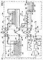
- FIG. 1 is a very schematic view of a circuit of unloading the liquefied gas 201 from the ship 200 carrying this liquefied gas to the gas terminal 206.
- the liquefied gas 201 transported in the tank 202 of the vessel 200 is discharged to a tank 204 of the gas terminal 206 by a means for transferring the liquefied gas.
- This transfer means comprises a circuit 210 of liquefied gas having a loading arm 212 and another vapor circuit 228 of gas comprising another loading arm 230.
- the arms of loading 212 and 230 ensure a certain freedom of movement between the ship 200 and the gas terminal 206 and are connected between a gas transfer interface 260 at the level of the ship 200 and another interface 262 for transferring gas on the gas terminal side 206.
- the transfer means also comprises a pump 208, which can to be immersed in the tank 202 of the ship 200 and which delivers the liquefied gas present in this tank 202 to the tank 204 of the gas terminal 206.
- circuit 228 connects the gaseous sky 224 of the tank 202 to the gaseous sky 226 of the tank 204 to ensure the pressure control vapors in gaseous skies 224 and 226.
- excess gas vapor in the sky gaseous vessel 224 of the vessel 202 of the vessel 200 and the gaseous sky 226 of the tank 204 of the gas terminal 206 can be used to supply the propulsion system 250 of the ship 200 through the circuit 228.
- the propulsion system 250 of the ship 200 is based on the use of a 253 diesel or turbine type engine gas that can be fed by gas vapor to drive one or several alternators 255 supplying one or more electric motors 257 driving one or more propellers 259.
- the liquefied gas 201 contained in the tank 204 of the gas terminal 206 is transferred by a pump 216 immersed in this tank 204, to a 220 high pressure pump discharging this liquefied gas 201 to a heat exchanger 222 so that it is re-gasified before send it, at a substantially ambient temperature, to the pipeline 214.
- the heat produced by the propulsion system 250 of the ship 200 is used to supply heat to the heat exchanger 222 disposed in the gas terminal 206.
- the propulsion system 250 of the ship 200 is then used as a co-generation unit supplying the gas terminal 206 with a fluid heat carrier.
- the heat generated by the 253 engine of the diesel or turbine type gas can be captured by a cooling circuit 264 of this engine 253 for supplying with a pump 266 a fluid network 268 coolant, for example pressurized water or not, which, via arms or hoses 270 and 272 supply hot fluid exchanger 222 which performs the re-gasification.
- a fluid network 268 coolant for example pressurized water or not
- the arms or hoses 270 and 272 are connected between an interface supply 274 of the heat transfer fluid at the vessel 200 and a receiving interface 276 of the heat transfer fluid at the terminal gas 206.
- the power interface 274 is intended to circulate the heat transfer fluid of the engine 253 of the system propulsion 250 of the ship 200 in the heat exchanger 222.
- This co-generation means allows to optimize the installations thus improving economic performance and ecological, because the necessary investment is largely under the propulsion of the ship itself and the gas terminal did not need to have his own co-generation facility.
- a specific part of the electric power supplied by the propulsion system 250 of the ship 200 is used to supply electricity to the gas terminal 206.
- the electrical circuit 256 has a flexible connection 258 between an interface 261 for supplying electrical power at the level of ship 200 and an interface 263 for receiving electrical power at level of the gas terminal 206.
- the electric power required for propulsion the vessel 200 is five to ten times loading or unloading of cargo, where its main needs are those relating to the power supply of the submerged pumps 208, whose consumption is much lower than that of the main engines 257 when the ship 200 is underway.
- the propulsion system 250 of the ship 200 is used as a co-generation unit supplying the gas terminal 206 not only a heat energy but also power electric.
- the ship's ballast 242 is filled with water 278 supplied by the gas terminal 206 and not by sea water.
- the water 278 is supplied by the gas terminal 206 via a supply circuit 280 connected to the ship 200 by a loading arm or a hose 282.
- the loading arm is connected between an interface 284 ballast water level vessel 200 and a water interface 286 at the gas terminal 206.
- These water interfaces 284 and 286 allow the transfer of water 278 between the gas terminal 206 and the vessel 200.
- the power supply circuit 280 can be used to supplying the heat exchanger 222 with heat in order to re-gasify the gas liqué message.
- This device makes it possible to use seawater for ballasting which can be previously decanted in a basin 288 where the mud 290 can be deposited, allowing to supply clean water 278 via a pump 292 the exchanger 222 then the ballast 242 of the vessel 200.
- this 278 water can be fresh water stored in the basin 288 and powered by a circuit 294. Indeed, most unloading gas terminals are in geographical areas where freshwater resources are abundant.
- ballasts 242 The silt deposits in ballasts 242 are thus avoided resulting in significant savings.
- a ship can collect up to 1000 tonnes of silt per year in its ballast tanks.
- the use of fresh water reduces, on the one hand, the ship ballast, which leads to a reduction in maintenance costs and allows on the other hand to load on the ship at level of the unloading gas terminals a water that has a value Merchant.
- the loading terminals belonging to countries exporting natural gas or liquefied petroleum are located most in arid or desert regions.
- Figure 2 is a first variant showing that heat produced by the propulsion system 250 of the ship 200 can be used to heat the water 278 in the basin 288 so that it can be used like a thermal accumulator.
- the basin 288 can be used as a heat accumulator for supplying the heat exchanger 222.
- the water contained in this basin 288 is thus warmed up, when a ship is connected, by a heat exchanger 296 via a circuit 298 of heat transfer fluid connected to the network 268.
- the re-gasification exchanger 222 can thus be supplied with hot water coming either from the network 268 of coolant coming from ship 200 when it is unloading, that is, when the ship 200 is not available to provide this hot water, by the 299 circuit that is fed by the warmed water stored in the basin 288.
- This architecture thus allows, possibly using a combination of these two sources of hot water optimize at best, in according to the needs of the gas terminal 206, the use of calories supplied by the ship 200 during unloading.
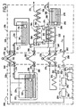
- Figure 3 shows a second variant allowing value, even better, using a positive cycle of recovery of energy represented by a loop 302, the calories provided by the ship 200.
- This energy recovery loop 302 is formed between a cold source 304 at the level of the re-gasification of the liquefied gas and a hot source 306 at the heat exchanger 222.
- the cold source 304 is constituted by the frigories provided by the gas liquefied when re-gasification.
- the energy recovery loop 302 may, for example, be a Rankine cycle where the cycle fluid is liquefied by the frigories supplied by the liquefied gas in a heat exchanger / condenser 308, and then under pressure by a pump 310 which can for example be on a same shaft as an alternator 312 and a turbine 314.
- the fluid of the loop 302 is then vaporized under pressure in the exchanger 222 by the heat transfer fluid circuit 268 from the ship 200, then relaxed in the turbine 314 before returning to the vaporizer / condenser 308.
- this temperature is advantageous for this temperature to be maximum, that is, as close as possible to the maximum exchange temperature can be provided by the ship 200 which can be of the order of 80 ° C in the case of a diesel engine cooling circuit 264 253.
- an additional heat exchanger 316 water fed or not, can be arranged at the exit of the cold source 304 so that the gas temperature after its re-gasification, is sufficient to allow its injection directly into the pipeline 214.
- This additional heat exchanger 316 may for example be powered by the heat produced by the propulsion system 250 of the ship 200 or by the supply circuit 280 of the ballast water.
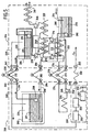
- Figure 4 shows another variant comprising another heat exchanger 320 supplied from a heat transfer circuit 322.
- This heat exchanger 320 may for example correspond to a second stage of overheating, added to the heat exchanger 222 of the figure 1.
- the heat produced in the exhaust 324 of the engine 250 of the propulsion system 250 of the ship 200 can be captured by a cooling circuit 326 to feed with a pump 328 the circuit 322 heat transfer fluid.
- Arms or hoses 332 and 334 are connected between an interface supply 336 of the heat transfer fluid at the ship 200 and a receiving interface 338 of the heat transfer fluid at the terminal gas 206.
- the calories collected in the exhaust 324 can increase the temperature of the heat transfer fluid to a temperature of the order of 150 ° C.
- the heat transfer fluid can be, for example, pressurized water, or water vapor, or even oil.
- FIG. 5 is a variant of FIG. circuit 342 of energy recovery.
- This example makes it possible to further improve the valuation of frigories released by the liquefied gas during its re-gasification, by carrying, by means of the pump 220, a pressure greater than that required by the pipeline 214.
- the liquefied gas is re-gasified in the exchanger 344, it can be overheated in another exchanger, for example in the heat exchanger 320 fed by the heat produced at the level of exhaust gas as shown in Figure 4.
- the gas is then expanded to the service pressure of the pipeline 214 in a turbine 346 which can be coupled to an alternator (not represented) to provide power to the network, that is, as is proposed in Figure 5, can be mounted on the same shaft as the motor 348 of the pump 220 to reduce its consumption electric.
- This relaxation causes a drop in temperature, thus, the gas can be warmed to a substantially ambient temperature by the additional exchanger 316 before being admitted into the pipeline 214.
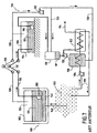
- FIG. 6 is a very schematic view of a circuit of loading liquefied gas from a gas terminal 206 of loading to a ship 200 carrying this liquefied gas.
- the propulsion system 250 of the ship 200 is used as a co-generation unit to feed the gas terminal 206 in heat and electricity.
- the heat transported by the circuit 268 via the arms 270 and 272, is for example released by a heat exchanger 352 to feed a facility 354 consuming heat.
- the electricity produced by the generator (s) 255 ship 200 can be used to power via the electrical circuit 256 the power network of the gas terminal 206.
- the ship 200 can send it by means of a pump 362 and possibly 363, through a circuit 364 of water to the terminal gas 206 where it can be used as a coolant in a heat exchanger 366 for the benefit, for example of a circuit of 367 cooling of a plant or liquefaction plant (no represent).
- the water circuit 364 comprises an arm or a hose of loading 368 connected between a ballast water interface 372 to vessel level 200 and a water interface 374 at the terminal gas 206.
- ballast water can be sent through additional pumps integrated into the terminal, to achieve greater pressure to a local network for, for example, irrigation purposes.
- ballast water is like fluid of cooling as a source of fresh water is particularly interesting for the gas loading terminals that are placed in desert or arid areas.
Landscapes
- Engineering & Computer Science (AREA)
- Mechanical Engineering (AREA)
- Chemical & Material Sciences (AREA)
- Combustion & Propulsion (AREA)
- Ocean & Marine Engineering (AREA)
- General Engineering & Computer Science (AREA)
- Filling Or Discharging Of Gas Storage Vessels (AREA)
Description
- la figure 1 est une vue très schématique d'un circuit de déchargement du gaz liquéfié à partir d'un navire transportant ce gaz liquéfié vers un terminal gazier conforme à l'invention montrant que de l'énergie produite par le système propulsif du navire est fournie au terminal gazier;
- la figure 2 est une première variante de la figure 1 montrant que la chaleur produite par le système propulsif du navire peut être utilisée pour chauffer l'eau dans un bassin ;
- la figure 3 est une deuxième variante de la figure 1 comportant un cycle de récupération d'énergie ;
- la figure 4 est une troisième variante de la figure 1 comportant deux échangeurs thermiques ;
- la figure 5 est une variante de la figure 4 comportant deux cycles de récupération d'énergie ;
- la figure 6 est une vue très schématique d'un circuit de chargement du gaz liquéfié à partir d'un terminal gazier vers un navire transportant ce gaz liquéfié conforme à l'invention ;
- la figure 7 est une vue très schématique d'un circuit de déchargement du gaz liquéfié à partir d'un navire transportant ce gaz liquéfié vers un terminal gazier selon l'art antérieur ; et
- la figure 8 est une vue très schématique d'un circuit de chargement du gaz liquéfié à partir d'un terminal gazier vers un navire transportant ce gaz liquéfié selon l'art antérieur.
Claims (28)
- Procédé d'alimentation en énergie d'un terminal gazier (206) à partir d'un navire (200) transportant du gaz liquéfié lors d'un transfert de ce gaz liquéfié entre une cuve (202) du navire (200) et un réservoir (204) du terminal gazier (206), caractérisé en ce qu'une partie de l'énergie produite par le système propulsif (250) du navire (200) est fournie au terminal gazier (206).
- Procédé selon la revendication 1, caractérisé en ce que des excès de vapeurs de gaz dans le ciel gazeux (224) de la cuve (202) du navire (200) et le ciel gazeux (226) du réservoir (204) du terminal gazier (206) sont utilisés pour alimenter le système propulsif (250) du navire (200).
- Procédé selon l'une quelconque des revendications 1 et 2, caractérisé en ce que la chaleur produite par le système propulsif (250) du navire (200) est utilisée pour alimenter au moins un échangeur thermique (222, 296, 316, 320, 356) disposé dans le terminal gazier (206) pour alimenter ce dernier en chaleur.
- Procédé selon la revendication 3, caractérisé en ce qu'un premier échangeur thermique (222) est alimenté à partir d'un circuit de refroidissement (264) du moteur (253) du système propulsif (250) du navire (200).
- Procédé selon la revendication 3, caractérisé en ce qu'un second échangeur thermique (320) est alimenté à partir d'un circuit caloporteur (322) au niveau des gaz d'échappement (324) du moteur (253) du système propulsif (250) du navire (200).
- Procédé selon l'une quelconque des revendications 1 à 5, caractérisé en ce que la chaleur dégagée par le premier échangeur thermique (222) ou/et le second échangeur thermique (320) est utilisée pour re-gazéifier le gaz liquéfié après avoir été déchargé de la cuve (202) du navire (200) vers le réservoir (204) du terminal gazier (206).
- Procédé selon l'une quelconque des revendications 1 à 6, caractérisé en ce qu'au moins un cycle positif de récupération d'énergie (302) est formé entre une source froide (304) au niveau de la re-gazéification et une source chaude (306) au niveau du premier échangeur thermique (222) ou/et le second échangeur thermique (320).
- Procédé selon l'une quelconque des revendications 6 et 7, caractérisé en ce qu'après sa re-gazéification, le gaz est réchauffé par un échangeur thermique supplémentaire (316).
- Procédé selon l'une quelconque des revendications 1 à 8, caractérisé en ce que lors d'un déchargement du gaz liquéfié du navire (200) vers le terminal gazier (206), des ballasts (242) du navire (200) sont remplis par de l'eau (278) fournie par le terminal gazier (206).
- Procédé selon la revendication 9, caractérisé en ce que l'eau fournie par le terminal gazier (206) est une eau de mer décantée dans un bassin (288).
- Procédé selon la revendication 9, caractérisé en ce que l'eau fournie par le terminal gazier (206) est une eau douce stockée dans un bassin (288).
- Procédé selon l'une quelconque des revendications 9 à 11, caractérisé en ce que l'eau fournie par le terminal gazier (206) est utilisée pour alimenter en chaleur l'échangeur thermique (222) afin de re-gazéifier le gaz liquéifié.
- Procédé selon l'une quelconque des revendications 10 et 11, caractérisé en ce que la chaleur produite par le système propulsif (250) du navire (200) est utilisée pour chauffer l'eau dans le bassin (288) afin que ce dernier puisse être utilisé comme un accumulateur thermique.
- Procédé selon la revendication 13, caractérisé en ce que l'accumulateur thermique formé par le bassin (288) d'eau est utilisé pour re-gazéifier le gaz liquéfié dans le terminal gazier (206).
- Procédé selon l'une quelconque des revendications 1 à 8, caractérisé en ce que lors d'un chargement du gaz liquéfié du terminal gazier (206) vers le navire (200), l'eau présente dans les ballasts (242) du navire (200) est envoyée vers le terminal gazier (206).
- Procédé selon la revendication 15, caractérisé en ce que l'eau envoyée vers le terminal gazier (206) est utilisée comme fluide de refroidissement dans un échangeur thermique (366) dans le terminal gazier (206).
- Procédé selon la revendication 16, caractérisé en ce que l'échangeur thermique (366) est utilisé dans un circuit de refroidissement (367) d'une installation de liquéfaction.
- Procédé selon l'une quelconque des revendications 1 à 17, caractérisé en ce qu'une partie déterminée de la puissance électrique fournie par le système propulsif (250) du navire (200) est utilisée pour alimenter en électricité le terminal gazier (206).
- Procédé selon l'une quelconque des revendications 1 à 18, caractérisé en ce que le gaz liquéfié est du gaz naturel liquéfié.
- Procédé selon l'une quelconque des revendications 1 à 18, caractérisé en ce que le gaz liquéfié est du gaz de pétrole liquéfié.
- Navire comportant une cuve (202) pour le transport de gaz liquéfié, un système propulsif (250) et un moyen de transfert de ce gaz liquéfié entre la cuve (202) du navire (200) et un réservoir (204) d'un terminal gazier (206), caractérisé en ce qu'il comporte en outre au moins une interface (274) d'alimentation en fluide caloporteur destiné à alimenter le terminal gazier (206) en chaleur.
- Navire selon la revendication 21, caractérisé en ce qu'une première interface (274) d'alimentation en fluide caloporteur est destinée à faire circuler le fluide caloporteur de refroidissement du moteur (253) du système propulsif (250) du navire (200) dans un premier échangeur thermique (222) disposé dans le terminal gazier (206).
- Navire selon l'une quelconque des revendications 21 et 22, caractérisé en ce qu'une seconde interface (336) d'alimentation en fluide caloporteur est destinée à faire circuler le fluide caloporteur de refroidissement au niveau des gaz d'échappement (324) du moteur (253) du système propulsif (250) du navire (200) dans un second échangeur thermique (320) disposé dans le terminal gazier (206).
- Navire selon l'une quelconque des revendications 21 à 23, caractérisé en ce qu'il comporte en outre une interface (284) d'eau de ballastage permettant un transfert d'eau entre le navire (200) et le terminal gazier (206).
- Navire selon l'une quelconque des revendications 21 à 24, caractérisé en ce qu'il comporte en outre une interface (261) de fourniture de puissance électrique permettant d'alimenter en électricité le terminal gazier (206).
- Terminal gazier comportant au moins un réservoir (204) pour le stockage de gaz liquéfié et un moyen de transfert de ce gaz liquéfié entre ce réservoir (204) et une cuve (202) d'un navire (200) de transport du gaz liquéfié, caractérisé en ce qu'il comporte en outre au moins une interface (276) de réception d'un fluide caloporteur à partir du navire (200).
- Terminal gazier selon la revendication 26, caractérisé en ce qu'il comporte en outre une interface (286) d'eau permettant un transfert d'eau entre le navire (200) et le terminal gazier (206).
- Terminal gazier selon l'une quelconque des revendications 26 et 27, caractérisé en ce qu'il comporte en outre une interface (263) de réception de puissance électrique permettant d'alimenter en électricité le terminal gazier (206) à partir du navire (200).
Applications Claiming Priority (2)
| Application Number | Priority Date | Filing Date | Title |
|---|---|---|---|
| FR0303430A FR2852590B1 (fr) | 2003-03-20 | 2003-03-20 | Alimentation en energie d'un terminal gazier a partir d'un navire transportant du gaz liquefie |
| FR0303430 | 2003-03-20 |
Publications (2)
| Publication Number | Publication Date |
|---|---|
| EP1460331A1 EP1460331A1 (fr) | 2004-09-22 |
| EP1460331B1 true EP1460331B1 (fr) | 2005-10-05 |
Family
ID=32799701
Family Applications (1)
| Application Number | Title | Priority Date | Filing Date |
|---|---|---|---|
| EP20040290682 Expired - Lifetime EP1460331B1 (fr) | 2003-03-20 | 2004-03-12 | Alimentation en énergie d'un terminal gazier à partir d'un navire transportant du gaz liquéfié |
Country Status (14)
| Country | Link |
|---|---|
| US (1) | US7287389B2 (fr) |
| EP (1) | EP1460331B1 (fr) |
| JP (1) | JP2004284579A (fr) |
| KR (1) | KR20040083005A (fr) |
| CN (1) | CN100579859C (fr) |
| AT (1) | ATE306046T1 (fr) |
| CA (1) | CA2519385A1 (fr) |
| DE (1) | DE602004000107D1 (fr) |
| EG (1) | EG24043A (fr) |
| ES (1) | ES2249751T3 (fr) |
| FR (1) | FR2852590B1 (fr) |
| NO (1) | NO20041162L (fr) |
| RU (1) | RU2005128269A (fr) |
| WO (1) | WO2004085912A1 (fr) |
Families Citing this family (32)
| Publication number | Priority date | Publication date | Assignee | Title |
|---|---|---|---|---|
| US7119460B2 (en) * | 2004-03-04 | 2006-10-10 | Single Buoy Moorings, Inc. | Floating power generation system |
| FR2877509B1 (fr) * | 2004-11-03 | 2007-04-13 | Alstom Sa | Systeme interface de transfert d'ernergie electrique entre un navire et une installation portuaire |
| JP2008519210A (ja) * | 2004-11-05 | 2008-06-05 | エクソンモービル アップストリーム リサーチ カンパニー | Lng輸送容器及び炭化水素を輸送するための方法 |
| AU2006241566B2 (en) * | 2005-05-04 | 2010-12-16 | Single Buoy Moorings Inc. | Large distance offshore LNG export terminal with boil-off vapour collection and utilization capacities |
| US20070214804A1 (en) * | 2006-03-15 | 2007-09-20 | Robert John Hannan | Onboard Regasification of LNG |
| US8069677B2 (en) * | 2006-03-15 | 2011-12-06 | Woodside Energy Ltd. | Regasification of LNG using ambient air and supplemental heat |
| US20070214805A1 (en) * | 2006-03-15 | 2007-09-20 | Macmillan Adrian Armstrong | Onboard Regasification of LNG Using Ambient Air |
| WO2008031146A1 (fr) * | 2006-09-11 | 2008-03-20 | Woodside Energy Limited | Gestion de gaz évaporés durant un transfert de gaz naturel liquide (lng) de navire à navire |
| DE102008031698A1 (de) † | 2007-11-02 | 2009-06-04 | Siemens Aktiengesellschaft | Schwimmfähige Hafenstromversorgung |
| US20090126372A1 (en) * | 2007-11-16 | 2009-05-21 | Solomon Aladja Faka | Intermittent De-Icing During Continuous Regasification of a Cryogenic Fluid Using Ambient Air |
| US20110030391A1 (en) * | 2009-08-06 | 2011-02-10 | Woodside Energy Limited | Mechanical Defrosting During Continuous Regasification of a Cryogenic Fluid Using Ambient Air |
| KR100967818B1 (ko) * | 2009-10-16 | 2010-07-05 | 대우조선해양 주식회사 | 액화연료가스 급유선 |
| KR101654188B1 (ko) * | 2009-10-30 | 2016-09-05 | 대우조선해양 주식회사 | 액화연료가스 급유선 및 급유 방법 |
| KR101649502B1 (ko) * | 2010-01-08 | 2016-08-19 | 대우조선해양 주식회사 | 에너지 절감 시스템 및 방법 |
| KR101239352B1 (ko) * | 2010-02-24 | 2013-03-06 | 삼성중공업 주식회사 | 부유식 lng 충전소 |
| AT509334B1 (de) * | 2010-07-09 | 2011-08-15 | Lo Solutions Gmbh | Verfahren und vorrichtung zur bereitstellung von elektrischer und thermischer energie, insbesondere in einer hafenanlage |
| US20120090335A1 (en) * | 2010-10-15 | 2012-04-19 | Hector Villarreal | Method and system for installation and maintenance of a submerged pump |
| JP5705588B2 (ja) * | 2011-02-28 | 2015-04-22 | 三菱重工業株式会社 | バラスト水処理システム、船舶および浮体式構造物 |
| FR2973098B1 (fr) * | 2011-03-22 | 2014-05-02 | Gaztransp Et Technigaz | Cuve etanche et thermiquement isolante |
| JP5890748B2 (ja) * | 2012-05-22 | 2016-03-22 | 川崎重工業株式会社 | 液体水素製造装置 |
| JP6021430B2 (ja) * | 2012-05-22 | 2016-11-09 | 川崎重工業株式会社 | 液体水素貯槽から発生するボイルオフガスの再液化方法 |
| AU2012216352B2 (en) | 2012-08-22 | 2015-02-12 | Woodside Energy Technologies Pty Ltd | Modular LNG production facility |
| CN103617503B (zh) * | 2013-12-05 | 2016-08-24 | 中国海洋石油总公司 | 一种lng接收站动态站间转运预测调度方法 |
| GB2535425A (en) * | 2014-07-30 | 2016-08-24 | Liquid Gas Equipment Ltd | LNG bunker vessel |
| KR101640781B1 (ko) * | 2014-09-26 | 2016-07-19 | 대우조선해양 주식회사 | 중고 lng운반선을 개조하여 부유식 해상 구조물로 자원을 지원하는 방법 |
| KR102333070B1 (ko) * | 2015-04-29 | 2021-12-01 | 대우조선해양 주식회사 | 해양구조물의 높이조절형 액화가스 하역 시스템 및 하역 방법 |
| CN106813102A (zh) * | 2015-12-02 | 2017-06-09 | 深圳中燃哈工大燃气技术研究院有限公司 | Lng加气站bog微型热电联产装置 |
| USRE50076E1 (en) * | 2015-12-30 | 2024-08-13 | Hyundai Heavy Industries Co., Ltd. | Liquefied gas carrier |
| CN105698000B (zh) * | 2016-01-31 | 2018-01-23 | 江苏韩通船舶重工有限公司 | 一种用于压缩天然气船舶气体装卸载系统及其工作方法 |
| CN109563967B (zh) * | 2016-05-11 | 2021-04-02 | 创新低温系统公司 | 气体储存及处理设备 |
| WO2018144024A1 (fr) * | 2017-02-05 | 2018-08-09 | Pcore Energy Llc | Regazéification de gaz naturel liquéfié et système d'optimisation de chaleur de production d'énergie |
| KR102136166B1 (ko) * | 2018-08-09 | 2020-07-21 | 재단법인한국조선해양기자재연구원 | Lng 벙커링 기자재 시험평가 설비 |
Family Cites Families (15)
| Publication number | Priority date | Publication date | Assignee | Title |
|---|---|---|---|---|
| DE539478C (de) * | 1929-05-14 | 1931-11-26 | Richard Leiser Dr | Verfahren zum Transport verfluessigter Gase bei tiefer Temperatur |
| US2903860A (en) * | 1955-09-13 | 1959-09-15 | Constock Liquid Methane Corp | Apparatus for unloading cold low temperature boiling liquids from storage reservoir |
| US3400545A (en) * | 1965-05-31 | 1968-09-10 | Shell Oil Co | Use of cold-carriers in liquefaction and regasification of gases |
| FR2122307B1 (fr) * | 1971-01-19 | 1975-01-17 | Denis Louis | |
| CH570296A5 (fr) * | 1972-05-27 | 1975-12-15 | Sulzer Ag | |
| JPS61262575A (ja) * | 1986-04-25 | 1986-11-20 | 三井造船株式会社 | 液化ガス気化装置における気化熱の有効利用方法 |
| FR2722760B1 (fr) * | 1994-07-22 | 1996-08-23 | Chantiers De Latlantique | Installation de propulsion sur un navire de transport de gaz liquefie |
| NO180469B1 (no) * | 1994-12-08 | 1997-05-12 | Statoil Petroleum As | Fremgangsmåte og system for fremstilling av flytendegjort naturgass til havs |
| JP2744213B2 (ja) * | 1995-11-02 | 1998-04-28 | 川崎重工業株式会社 | 液化ガス運搬船用貨物部の熱交換器及びその熱交換装置 |
| US6230809B1 (en) * | 1997-01-16 | 2001-05-15 | Jens Korsgaard | Method and apparatus for producing and shipping hydrocarbons offshore |
| US6089022A (en) * | 1998-03-18 | 2000-07-18 | Mobil Oil Corporation | Regasification of liquefied natural gas (LNG) aboard a transport vessel |
| TW586262B (en) * | 1999-02-16 | 2004-05-01 | Exxonmobil Upstream Res Co | Systems and methods for utilizing excess electric power from a marine transportation vessel |
| NO308714B1 (no) * | 1999-07-09 | 2000-10-16 | Moss Maritime As | Undervannsfordamper for LNG |
| US20020073619A1 (en) * | 2000-12-14 | 2002-06-20 | William Perkins | Method and apparatus for delivering natural gas to remote locations |
| US6546739B2 (en) * | 2001-05-23 | 2003-04-15 | Exmar Offshore Company | Method and apparatus for offshore LNG regasification |
-
2003
- 2003-03-20 FR FR0303430A patent/FR2852590B1/fr not_active Expired - Fee Related
-
2004
- 2004-03-12 AT AT04290682T patent/ATE306046T1/de not_active IP Right Cessation
- 2004-03-12 ES ES04290682T patent/ES2249751T3/es not_active Expired - Lifetime
- 2004-03-12 DE DE200460000107 patent/DE602004000107D1/de not_active Expired - Lifetime
- 2004-03-12 EP EP20040290682 patent/EP1460331B1/fr not_active Expired - Lifetime
- 2004-03-19 CA CA 2519385 patent/CA2519385A1/fr not_active Abandoned
- 2004-03-19 KR KR1020040018918A patent/KR20040083005A/ko not_active Ceased
- 2004-03-19 WO PCT/FR2004/000674 patent/WO2004085912A1/fr not_active Ceased
- 2004-03-19 JP JP2004080420A patent/JP2004284579A/ja not_active Ceased
- 2004-03-19 RU RU2005128269/06A patent/RU2005128269A/ru not_active Application Discontinuation
- 2004-03-19 US US10/804,634 patent/US7287389B2/en not_active Expired - Fee Related
- 2004-03-19 NO NO20041162A patent/NO20041162L/no not_active Application Discontinuation
- 2004-03-22 CN CN200410030194A patent/CN100579859C/zh not_active Expired - Fee Related
-
2005
- 2005-09-20 EG EGNA2005090561 patent/EG24043A/xx active
Also Published As
| Publication number | Publication date |
|---|---|
| FR2852590B1 (fr) | 2005-06-17 |
| FR2852590A1 (fr) | 2004-09-24 |
| US7287389B2 (en) | 2007-10-30 |
| JP2004284579A (ja) | 2004-10-14 |
| CN1532115A (zh) | 2004-09-29 |
| KR20040083005A (ko) | 2004-09-30 |
| RU2005128269A (ru) | 2006-03-20 |
| US20040182090A1 (en) | 2004-09-23 |
| CN100579859C (zh) | 2010-01-13 |
| ATE306046T1 (de) | 2005-10-15 |
| EP1460331A1 (fr) | 2004-09-22 |
| WO2004085912A1 (fr) | 2004-10-07 |
| CA2519385A1 (fr) | 2004-10-07 |
| NO20041162L (no) | 2004-09-21 |
| DE602004000107D1 (de) | 2005-11-10 |
| EG24043A (en) | 2008-04-13 |
| ES2249751T3 (es) | 2006-04-01 |
Similar Documents
| Publication | Publication Date | Title |
|---|---|---|
| EP1460331B1 (fr) | Alimentation en énergie d'un terminal gazier à partir d'un navire transportant du gaz liquéfié | |
| EP1650125B1 (fr) | Système énergétique mettant en oeuvre du gaz naturel stocké sous forme liquide et des machines thermoélectriques | |
| EP3044527B1 (fr) | Dispositif de récupération de vapeurs issues d'un réservoir cryogénique | |
| EP3743651A1 (fr) | Procede et systeme de traitement de gaz d'une installation de stockage de gaz pour un navire de transport de gaz | |
| EP3510317B1 (fr) | Installation, procédé pour stocker et reliquéfier un gaz liquéfié et véhicule de transport associé | |
| FR3077867A1 (fr) | Procede et systeme de traitement de gaz d'une installation de stockage de gaz pour un navire de transport de gaz | |
| WO2012066460A2 (fr) | Procede et installation de transport de gaz naturel liquefie | |
| WO2020109580A1 (fr) | Systeme de traitement de gaz d'un terminal de reception equipe d'une unite de regazeification et procede de traitement de gaz correspondant | |
| FR2785034A1 (fr) | Procede pour eliminer l'evaporation d'un gaz liquefie stocke dans une cuve etanche et isotherme, et dispositif pour sa mise en oeuvre | |
| BE1019090A3 (fr) | Dispositif pour l'alimentation en combustible d'une installation de production d'energie d'un navire. | |
| EP4281718A1 (fr) | Système d'alimentation en gaz pour appareils consommateurs de gaz à haute et basse pression | |
| EP2984386B1 (fr) | Systeme perfectionne de traitement et d'acheminement de gaz naturel comportant un circuit de chauffage de la cuve | |
| EP4222366A1 (fr) | Système d'alimentation en gaz pour appareils consommateurs de gaz à haute et basse pression | |
| KR20090125436A (ko) | 이중연료사용엔진이 장착된 액화천연가스 운반선의추진시스템 | |
| FR3141154A1 (fr) | Procédé DE GESTION D’UN FLUIDE SOUS FORME LIQUIDE CONTENU DANS UNE CUVE | |
| FR3066556B1 (fr) | Groupe motopropulseur avec source de chaleur additionnelle integree dans un circuit de fluide caloporteur | |
| FR3150995A1 (fr) | Vehicule a pile a combustible ou a moteur a combustion interne a dihydrogene comprenant un dispositif de recuperation d’energie | |
| WO2022253961A1 (fr) | Procédé de production d'électricité au moyen d'une installation destinée à être placée dans une étendue deau | |
| OA21467A (fr) | Procédé de production d'électricité au moyen d'une installation destinée à être placée dans une étendue d'eau | |
| FR3059355B1 (fr) | Installation de production d'energie electrique, d'energie mecanique et/ou de froid | |
| FR2510183A1 (fr) | Recuperateur d'energie des moteurs a combustion interne | |
| FR2917129A1 (fr) | Systeme de motorisation pour vehicules | |
| FR2892564A1 (fr) | Systeme de production d'energie electrique pour vehicule automobile | |
| FR3051512A1 (fr) | Systeme de production d'energie thermique a au moins un accumulateur de vapeur de stockage d'energie thermique provenant d'une installation solaire |
Legal Events
| Date | Code | Title | Description |
|---|---|---|---|
| PUAI | Public reference made under article 153(3) epc to a published international application that has entered the european phase |
Free format text: ORIGINAL CODE: 0009012 |
|
| AK | Designated contracting states |
Kind code of ref document: A1 Designated state(s): AT BE BG CH CY CZ DE DK EE ES FI FR GB GR HU IE IT LI LU MC NL PL PT RO SE SI SK TR |
|
| AX | Request for extension of the european patent |
Extension state: AL HR LT LV MK |
|
| 17P | Request for examination filed |
Effective date: 20050204 |
|
| GRAP | Despatch of communication of intention to grant a patent |
Free format text: ORIGINAL CODE: EPIDOSNIGR1 |
|
| AKX | Designation fees paid |
Designated state(s): AT BE BG CH CY CZ DE DK EE ES FI FR GB GR HU IE IT LI LU MC NL PL PT RO SE SI SK TR |
|
| GRAS | Grant fee paid |
Free format text: ORIGINAL CODE: EPIDOSNIGR3 |
|
| GRAA | (expected) grant |
Free format text: ORIGINAL CODE: 0009210 |
|
| RAP1 | Party data changed (applicant data changed or rights of an application transferred) |
Owner name: SNECMA |
|
| AK | Designated contracting states |
Kind code of ref document: B1 Designated state(s): AT BE BG CH CY CZ DE DK EE ES FI FR GB GR HU IE IT LI LU MC NL PL PT RO SE SI SK TR |
|
| PG25 | Lapsed in a contracting state [announced via postgrant information from national office to epo] |
Ref country code: RO Free format text: LAPSE BECAUSE OF FAILURE TO SUBMIT A TRANSLATION OF THE DESCRIPTION OR TO PAY THE FEE WITHIN THE PRESCRIBED TIME-LIMIT Effective date: 20051005 Ref country code: CZ Free format text: LAPSE BECAUSE OF FAILURE TO SUBMIT A TRANSLATION OF THE DESCRIPTION OR TO PAY THE FEE WITHIN THE PRESCRIBED TIME-LIMIT Effective date: 20051005 Ref country code: SK Free format text: LAPSE BECAUSE OF FAILURE TO SUBMIT A TRANSLATION OF THE DESCRIPTION OR TO PAY THE FEE WITHIN THE PRESCRIBED TIME-LIMIT Effective date: 20051005 Ref country code: FI Free format text: LAPSE BECAUSE OF FAILURE TO SUBMIT A TRANSLATION OF THE DESCRIPTION OR TO PAY THE FEE WITHIN THE PRESCRIBED TIME-LIMIT Effective date: 20051005 Ref country code: SI Free format text: LAPSE BECAUSE OF FAILURE TO SUBMIT A TRANSLATION OF THE DESCRIPTION OR TO PAY THE FEE WITHIN THE PRESCRIBED TIME-LIMIT Effective date: 20051005 Ref country code: AT Free format text: LAPSE BECAUSE OF FAILURE TO SUBMIT A TRANSLATION OF THE DESCRIPTION OR TO PAY THE FEE WITHIN THE PRESCRIBED TIME-LIMIT Effective date: 20051005 Ref country code: NL Free format text: LAPSE BECAUSE OF FAILURE TO SUBMIT A TRANSLATION OF THE DESCRIPTION OR TO PAY THE FEE WITHIN THE PRESCRIBED TIME-LIMIT Effective date: 20051005 Ref country code: IE Free format text: LAPSE BECAUSE OF FAILURE TO SUBMIT A TRANSLATION OF THE DESCRIPTION OR TO PAY THE FEE WITHIN THE PRESCRIBED TIME-LIMIT Effective date: 20051005 Ref country code: PL Free format text: LAPSE BECAUSE OF FAILURE TO SUBMIT A TRANSLATION OF THE DESCRIPTION OR TO PAY THE FEE WITHIN THE PRESCRIBED TIME-LIMIT Effective date: 20051005 |
|
| REG | Reference to a national code |
Ref country code: GB Ref legal event code: FG4D Free format text: NOT ENGLISH |
|
| REG | Reference to a national code |
Ref country code: CH Ref legal event code: EP |
|
| REG | Reference to a national code |
Ref country code: IE Ref legal event code: FG4D Free format text: LANGUAGE OF EP DOCUMENT: FRENCH |
|
| REF | Corresponds to: |
Ref document number: 602004000107 Country of ref document: DE Date of ref document: 20051110 Kind code of ref document: P |
|
| PG25 | Lapsed in a contracting state [announced via postgrant information from national office to epo] |
Ref country code: DK Free format text: LAPSE BECAUSE OF FAILURE TO SUBMIT A TRANSLATION OF THE DESCRIPTION OR TO PAY THE FEE WITHIN THE PRESCRIBED TIME-LIMIT Effective date: 20060105 Ref country code: BG Free format text: LAPSE BECAUSE OF FAILURE TO SUBMIT A TRANSLATION OF THE DESCRIPTION OR TO PAY THE FEE WITHIN THE PRESCRIBED TIME-LIMIT Effective date: 20060105 Ref country code: SE Free format text: LAPSE BECAUSE OF FAILURE TO SUBMIT A TRANSLATION OF THE DESCRIPTION OR TO PAY THE FEE WITHIN THE PRESCRIBED TIME-LIMIT Effective date: 20060105 |
|
| PG25 | Lapsed in a contracting state [announced via postgrant information from national office to epo] |
Ref country code: DE Free format text: LAPSE BECAUSE OF FAILURE TO SUBMIT A TRANSLATION OF THE DESCRIPTION OR TO PAY THE FEE WITHIN THE PRESCRIBED TIME-LIMIT Effective date: 20060106 |
|
| GBT | Gb: translation of ep patent filed (gb section 77(6)(a)/1977) |
Effective date: 20060103 |
|
| REG | Reference to a national code |
Ref country code: GR Ref legal event code: EP Ref document number: 20050403780 Country of ref document: GR |
|
| NLV1 | Nl: lapsed or annulled due to failure to fulfill the requirements of art. 29p and 29m of the patents act | ||
| PG25 | Lapsed in a contracting state [announced via postgrant information from national office to epo] |
Ref country code: MC Free format text: LAPSE BECAUSE OF NON-PAYMENT OF DUE FEES Effective date: 20060331 Ref country code: LU Free format text: LAPSE BECAUSE OF NON-PAYMENT OF DUE FEES Effective date: 20060331 |
|
| REG | Reference to a national code |
Ref country code: ES Ref legal event code: FG2A Ref document number: 2249751 Country of ref document: ES Kind code of ref document: T3 |
|
| PG25 | Lapsed in a contracting state [announced via postgrant information from national office to epo] |
Ref country code: HU Free format text: LAPSE BECAUSE OF FAILURE TO SUBMIT A TRANSLATION OF THE DESCRIPTION OR TO PAY THE FEE WITHIN THE PRESCRIBED TIME-LIMIT Effective date: 20060406 |
|
| REG | Reference to a national code |
Ref country code: IE Ref legal event code: FD4D |
|
| PLBE | No opposition filed within time limit |
Free format text: ORIGINAL CODE: 0009261 |
|
| STAA | Information on the status of an ep patent application or granted ep patent |
Free format text: STATUS: NO OPPOSITION FILED WITHIN TIME LIMIT |
|
| 26N | No opposition filed |
Effective date: 20060706 |
|
| PG25 | Lapsed in a contracting state [announced via postgrant information from national office to epo] |
Ref country code: EE Free format text: LAPSE BECAUSE OF FAILURE TO SUBMIT A TRANSLATION OF THE DESCRIPTION OR TO PAY THE FEE WITHIN THE PRESCRIBED TIME-LIMIT Effective date: 20051005 |
|
| REG | Reference to a national code |
Ref country code: CH Ref legal event code: PL |
|
| PG25 | Lapsed in a contracting state [announced via postgrant information from national office to epo] |
Ref country code: CY Free format text: LAPSE BECAUSE OF FAILURE TO SUBMIT A TRANSLATION OF THE DESCRIPTION OR TO PAY THE FEE WITHIN THE PRESCRIBED TIME-LIMIT Effective date: 20051005 |
|
| PG25 | Lapsed in a contracting state [announced via postgrant information from national office to epo] |
Ref country code: CH Free format text: LAPSE BECAUSE OF NON-PAYMENT OF DUE FEES Effective date: 20080331 Ref country code: LI Free format text: LAPSE BECAUSE OF NON-PAYMENT OF DUE FEES Effective date: 20080331 |
|
| PGFP | Annual fee paid to national office [announced via postgrant information from national office to epo] |
Ref country code: ES Payment date: 20100309 Year of fee payment: 7 Ref country code: PT Payment date: 20100301 Year of fee payment: 7 |
|
| PGFP | Annual fee paid to national office [announced via postgrant information from national office to epo] |
Ref country code: FR Payment date: 20100318 Year of fee payment: 7 Ref country code: IT Payment date: 20100311 Year of fee payment: 7 |
|
| PGFP | Annual fee paid to national office [announced via postgrant information from national office to epo] |
Ref country code: BE Payment date: 20100223 Year of fee payment: 7 Ref country code: GB Payment date: 20100226 Year of fee payment: 7 Ref country code: TR Payment date: 20100304 Year of fee payment: 7 |
|
| PGFP | Annual fee paid to national office [announced via postgrant information from national office to epo] |
Ref country code: GR Payment date: 20100222 Year of fee payment: 7 |
|
| REG | Reference to a national code |
Ref country code: PT Ref legal event code: MM4A Free format text: LAPSE DUE TO NON-PAYMENT OF FEES Effective date: 20110912 |
|
| BERE | Be: lapsed |
Owner name: *SNECMA Effective date: 20110331 |
|
| PG25 | Lapsed in a contracting state [announced via postgrant information from national office to epo] |
Ref country code: PT Free format text: LAPSE BECAUSE OF NON-PAYMENT OF DUE FEES Effective date: 20110912 |
|
| GBPC | Gb: european patent ceased through non-payment of renewal fee |
Effective date: 20110312 |
|
| REG | Reference to a national code |
Ref country code: FR Ref legal event code: ST Effective date: 20111130 |
|
| PG25 | Lapsed in a contracting state [announced via postgrant information from national office to epo] |
Ref country code: BE Free format text: LAPSE BECAUSE OF NON-PAYMENT OF DUE FEES Effective date: 20110331 |
|
| PG25 | Lapsed in a contracting state [announced via postgrant information from national office to epo] |
Ref country code: FR Free format text: LAPSE BECAUSE OF NON-PAYMENT OF DUE FEES Effective date: 20110331 |
|
| PG25 | Lapsed in a contracting state [announced via postgrant information from national office to epo] |
Ref country code: IT Free format text: LAPSE BECAUSE OF NON-PAYMENT OF DUE FEES Effective date: 20110312 Ref country code: GR Free format text: LAPSE BECAUSE OF NON-PAYMENT OF DUE FEES Effective date: 20111004 Ref country code: GB Free format text: LAPSE BECAUSE OF NON-PAYMENT OF DUE FEES Effective date: 20110312 |
|
| REG | Reference to a national code |
Ref country code: ES Ref legal event code: FD2A Effective date: 20120424 |
|
| PG25 | Lapsed in a contracting state [announced via postgrant information from national office to epo] |
Ref country code: ES Free format text: LAPSE BECAUSE OF NON-PAYMENT OF DUE FEES Effective date: 20110313 |
|
| PG25 | Lapsed in a contracting state [announced via postgrant information from national office to epo] |
Ref country code: TR Free format text: LAPSE BECAUSE OF NON-PAYMENT OF DUE FEES Effective date: 20110312 |