EP1460411A2 - Dispositif d'essai pour garnitures de friction pour freins et embrayages - Google Patents
Dispositif d'essai pour garnitures de friction pour freins et embrayages Download PDFInfo
- Publication number
- EP1460411A2 EP1460411A2 EP03027191A EP03027191A EP1460411A2 EP 1460411 A2 EP1460411 A2 EP 1460411A2 EP 03027191 A EP03027191 A EP 03027191A EP 03027191 A EP03027191 A EP 03027191A EP 1460411 A2 EP1460411 A2 EP 1460411A2
- Authority
- EP
- European Patent Office
- Prior art keywords
- measuring channel
- test
- test device
- side wall
- friction
- Prior art date
- Legal status (The legal status is an assumption and is not a legal conclusion. Google has not performed a legal analysis and makes no representation as to the accuracy of the status listed.)
- Granted
Links
Images
Classifications
-
- G—PHYSICS
- G01—MEASURING; TESTING
- G01N—INVESTIGATING OR ANALYSING MATERIALS BY DETERMINING THEIR CHEMICAL OR PHYSICAL PROPERTIES
- G01N19/00—Investigating materials by mechanical methods
- G01N19/02—Measuring coefficient of friction between materials
Definitions
- the invention relates to a test device for brake and clutch linings which have a friction lining, which is preferably arranged on a carrier plate, optionally with the interposition of an intermediate layer.
- Brake and clutch linings generally consist of the carrier plate and the friction lining.
- the intermediate layer which may be interposed, serves to improve the adhesion between the friction lining and the carrier plate.
- brake and clutch linings which only consist of the friction lining, are also under discussion.
- the friction linings are usually made from resin-bound bulk materials.
- the bulk materials are shaped in a press mold, and the connection to the carrier plate can be established at the same time.
- the friction linings are then hardened, under the action of pressure and temperature.
- the phenolic resins commonly used as binders crosslink and form phenolic resin bridges.
- the friction linings get their final strength.
- the surface After hardening, the surface is ground, whereby the friction lining is given its predetermined thickness. This is followed by scorching.
- the friction surface is subjected to a heat treatment at temperatures from 450 ° C to 750 ° C in order to be able to achieve the specified coefficient of friction during the first use. This is followed by further process steps, such as special grinding for creating a predetermined contour (grooves, beveled edges), adjusting the temperature and creating corrosion protection, for example by applying powder coating.
- the finished brake and clutch pads are subjected to a final inspection so that any rejects can be sorted out.
- the final inspection provides direct statements in front of everyone Things about compliance with dimensional tolerances. Chemical and physical methods must be used to obtain further information, for example on the friction materials. They only deliver results after a time-consuming and sometimes complex analysis. In case of doubt, it is not possible to produce until the results are presented, unless one wishes to accept a high proportion of the committee.
- the appearance of rejects also provides certain information for process control. So far, however, there has been no possibility of separately checking the correct execution of the individual process steps and of having the information determined flow directly into the process control in order to optimize it, with the aim of producing products of the highest quality with a minimum of rejects can.
- the object of the invention is to remedy this defect.
- test device is universally applicable and can be used before and after each process step. It provides the measured values that are necessary for the correct monitoring of the respective process step. Malfunctions that occur are recognized directly on site and can immediately flow into the process control and optimize it accordingly.
- the device according to the invention is suitable for closed production processes, the temperature-controlled process steps of which run very quickly, since a direct intervention in the production process is made possible.
- test specimens are placed in the measuring channel, taking a defined and stable three-point position. They rest on the floor with their lower arch, and with their rubbing surface they rest on the entire surface of the side wall inclined to the vertical. In this position, they slide down the inclined measuring channel and make themselves available for the required measurements.
- the measuring channel should be inclined at an angle of approx. 20 ° to the horizontal, whereby this inclination angle should be adjustable.
- an angle of inclination with respect to the vertical of approximately 60 ° has proven to be positive.
- the test specimens can be correctly aligned manually or by a handling device and inserted into the measuring channel.
- the measuring channel have a lead section which transfers the friction surface of the respective test specimen to the side wall of the measuring channel inclined against the vertical. This means that the test specimens are horizontal Position can be introduced into the lead section, whereupon they are then tilted into the measuring position under the effect of their own weight.
- the measuring channel have at least two light barriers arranged at a distance from one another in the channel direction for detecting the sliding time and thus the sliding speed of the respective test object. Since the test specimen in its three-point support rests with its entire surface on the side wall of the measuring channel inclined against the vertical and remains in this position during its passage through the measuring channel, the slipping speed depends, i.e. the time between passing the two light barriers depends directly on the coefficient of friction of the respective friction lining.
- the infeed speed i.e. the speed at which the test object passes the upstream light barrier of the test section must be defined.
- the inlet speed of the test object can be zero, i.e. the test object is placed on the measuring channel and begins to slide there.
- the feed rate of the test object is not known, it must be measured, for which purpose a light barrier further upstream is required.
- a chain of light barriers extending over at least one length section of the measuring channel. In this way, the speed is continuously recorded over the length of the measuring section.
- light barrier is to be interpreted broadly in connection with the present invention. In addition to diode and laser systems, it should include all systems suitable for the barrier, for example also infrared and reflection systems.
- At least one extends from the bottom of the measuring channel over at least one height section from its side walls extending row of light barriers is provided, these light barriers being arranged in a narrow grid.
- Each light barrier segment is damped differently depending on the geometry and the speed of the respective test object.
- the damping pattern is compared with the specified target value pattern and provides information about the basic geometry, the expansion that may have occurred and the functional dimensions of the test object.
- the bottom of the measuring channel forms an acute angle with its side wall inclined towards the vertical. This also enables a basic statement about the thickness of the test object. Depending on the thickness, the height at which the test object slides through the row of light barriers changes, which generates different signals.
- At least one coil of an associated resonant circuit is integrated in the side wall of the measuring channel inclined against the vertical. Due to its exact positional orientation, the test object is guided on the friction side at a defined distance over the coil, the friction material influencing the inductive properties of the coil and thus changing the resonance frequency of the resonant circuit. This frequency change can be easily recorded and provides information about the type of friction lining.
- a single, relatively large coil can be used.
- the signals of several small coils can also be electronically integrated. In both cases, the friction material can be clearly identified.
- the smaller coils can be arranged in a row, for example at right angles to the bottom of the measuring channel. An offset arrangement in the associated side wall of the measuring channel is also possible.
- the individual mixture distribution over the friction surface can be recorded.
- This distribution which usually differs from test object to test object, can be used as a "fingerprint" of the brake and clutch lining for product tracking. Other individual markings may become superfluous.
- the resonant circuits also provide information about the geometric relationships of the friction surface. In this way, the resonant circuits also react to inclined surfaces, grooving in the friction material and unevenness of the friction surface, e.g. Bubbles after grinding. In connection with the speed information, the location of grooves, slopes, etc. must be clearly located. In this way, the success of machining steps influencing the geometry can be checked.
- the measuring channel merges into a deflecting surface and that a sensor for detecting the impact pulse is provided at the transition point. This enables the mass of the test object to be determined.
- a sensor for detecting the impact pulse is provided at the transition point.
- an impact surface can also be used, on which the test object comes to a standstill.
- the mass determination can already begin with the base plate. Your specified weight results from the material, geometry and processing status.
- the weight of the green compact is made up of the weight of the lining carrier plate and that of the friction material weight, plus the weight of the intermediate layer material if necessary.
- the weight of the hardened brake or clutch lining is reduced by the grinding loss and then again by the weight of the grinding loss during special grinding. When scoring, there is a clear weight loss due to the gases removed.
- the deflection surface is usually the transition of the measuring channel into the horizontal. However, lateral deflection surfaces are also conceivable.
- the weight is recorded using the kinetic energy that the test object experiences due to the change in height in the measuring channel.
- the impact pulse can be detected by vibration sensors or acceleration sensors that work, for example, piezoelectrically or inductively, or also by structure-borne sound microphones.
- a quantitative weight detection is not possible in this way, but only a detection of deviations from a predetermined target value.
- pulse detection has the advantage that it can be carried out very quickly and even in a harsh machine environment. Pulse images (eg before grinding / after grinding) can also be compared mathematically.
- a temperature sensor is advantageously integrated in the side wall of the measuring channel inclined against the vertical.
- This feature is based on the knowledge that, in the case of temperature-controlled processes which are in the state of equilibrium, certain temperatures can be assigned to the individual process or manufacturing steps. If these temperatures change independently of the other process conditions, this is an indication that errors in the process management have occurred.
- the temperature sensor is installed flush in the side wall of the measuring channel and consequently detects the temperature on the friction surface.
- An outside temperature sensor is advantageously assigned to this temperature sensor in order to be able to detect changes in the ambient conditions.
- the senor device can be retrofitted. In this way, it can be equipped with additional flame monitoring or an additional smoke detector. It is also possible to assign position sensors.
- the test device according to the invention can be designed as a table device into which the test specimens, as already mentioned, are manually entered.
- it can be more advantageous to integrate the test device into a production system, namely there between successive processing stations.
- it is proposed to equip the test device with standard interfaces on the inlet and outlet side. This enables problem-free exchange and the arrangement of a plurality of test devices over the length of the production plant. If the individual method steps are carried out in assigned modules there, one of the test devices according to the invention can be arranged between adjacent modules.
- the test facilities can also be arranged in pairs, namely the outlet side of the upstream module and the inlet side of the downstream module. This enables redundant measurements and mutual checking of the measuring systems.
- the associated data processing device is subjected to a “learning mode”.
- the test facility is supplied with brake and clutch linings, the properties of which have been proven to be correct.
- the test device measures these deposits, and the data processing device records the determined data and stores them as target values.
- the influence of product scatter can be taken into account by a corresponding series of "taught good parts”.
- the data processing device stores the limit values.
- individual parameters can be entered manually in order to take tighter or broader tolerated error characteristics into account.
- the stored data records can be assigned to the respective articles.
- the data processing device is designed so that it can establish logical links between individual measured values.
- the data for the friction material shows a deviation
- this can be compared with the data of the slip speed, the impact pulse and the processing status (thickness, contour, special grinding). If the correlation of all these data points in a common direction, clear conclusions can be drawn, for example "friction material interchanged with the intermediate layer".
- the data processing device checks these relationships and creates a uniform, reliable image from the combination of the "fuzzy data".
- the data processing device determines that a clear trend is emerging from the individual data, even though they lie within their tolerance ranges, countermeasures can be derived from this. For example, if the thickness and weight increase, the grinding machine must be readjusted.
- the data processing device can independently determine different types of covering. It is therefore also possible to check pads of different types and contours in any order.
- the design of the test facility allows different types of flooring to be picked up without mechanical modification. It can also be used for sorting and selection tasks. She prefers to work with fuzzy logic.
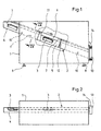
- the test device according to FIG. 1 has a housing 1 which contains a measuring channel 2.
- the measuring channel 2 is inclined with respect to the horizontal, so that test specimens 3 can slide down through the measuring channel.
- the test specimens 3, which in the present case are brake pads, are fed to the measuring channel 2 via an inlet device 4, in the correct orientation and with defined feed rate, the latter possibly being zero.
- the inlet channel 2 has two flat, parallel side walls 5 and 6 and a bottom 7.
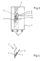
- the side walls 5 and 6 are inclined relative to the vertical, in the present case by approximately 60 °.
- the bottom 7 forms an acute angle with the side wall 5.
- the configuration is such that the test specimens 3 slide along with their friction surface on the side wall 5 during their passage through the measuring channel 2, while they are supported on the floor 7 with the lower arch of their lining carrier plate. This results in a three-point support, which guarantees the test objects 3 a defined, stable position.
- the angle of inclination chosen here from the vertical of approximately 60 ° is only an example. Other angles of inclination are conceivable.
- the angle of inclination of the measuring channel 2 with respect to the horizontal In the present case, it is approximately 20 °. However, it is important that the selected angle of inclination is adhered to in a defined manner. This is ensured by adjustable feet 8 of the housing 1. An incorrect alignment impairs the measuring accuracy.
- the test specimens 3 enter the measuring channel 2 at a defined feed rate.
- the measuring channel 2 has an upstream light barrier 9 and a downstream light barrier 10, which form a measuring section of a defined length. By recording the time that the test specimens 3 need to pass through this measuring section, conclusions can be drawn about the coefficient of friction of the respective friction surface.
- the measured values are entered into a data processing device (not shown) and compared there with a target value.
- the measuring channel 2 also contains a chain 11 of light barrier elements which extend in a narrow grid over the height of the measuring channel. This arrangement is used for contour checking.
- the test object runs through the row of light barrier elements, these being damped differently depending on the geometry and the speed (determined from the time measurement between light barriers 9 and 10).
- the damping pattern is compared with the stored target values via the data processing device.
- the row 11 of light barrier elements also allows a statement about the thickness of the test specimens 3. From Figure 4 it is clear that the thickness of the test specimens 3 determines their position at the level of the side wall 5 of the measuring channel 2. The data grid supplied by the light barrier elements of the row 11 changes accordingly.
- a series of coils 12 is also provided, to which associated resonant circuits are assigned.
- the test specimens 3 are guided along these coils 12 at a defined distance, influencing their inductance. This in turn leads to an adjustment of the resonance frequency of the associated resonant circuits.
- the frequency changes can be easily measured and are therefore correlated to the respective friction material.
- a comparison with the associated target values provides information about any deviations.
- the large number of coils 12 not only permits identification of the friction material, but also provides information about its distribution over the surface of the friction lining. An assigned "fingerprint" can thus be created for each test object 3.
- a deflection surface 13 adjoins the measuring channel 2, and a sensor 14 for detecting the impact pulse is assigned to it.
- the impact pulse in connection with the known slipping speed gives information about the mass of the respective test object 3. Deviations from the specified target value indicate that previous work steps, such as grinding or scorching, did not proceed correctly.
- Another This arrangement can be used to test the lining carrier plate alone for correctness.
- a temperature sensor 15 is also arranged in the side wall 5 of the measuring channel 2. It provides information about the temperature of the respective test object 3. The temperature indicates whether the previous process step has been carried out properly.
- An outside temperature sensor not shown, serves to compensate for the temperature influences of the environmental conditions.
- the measuring channel 2 is made of a wear and temperature resistant material. Ceramic materials are particularly suitable, but also other materials, as long as they do not influence the inductive sensors of the resonant circuits.
- the light barrier elements are embedded in the respective side wall and can be protected against mechanical damage with a protective glass or protective film. Contamination can be recognized and compensated for by the control of the light barriers. Cleaning devices can also be provided. Finally, there is the possibility that the test device emits a signal if the light barriers run the risk of finally failing due to contamination.
- test specimens There are special requirements for the design of the impact point at which the impact pulse is detected. On the one hand, a high degree of wear resistance is required, on the other hand, the test specimens must not be damaged. The test specimens leave the test facility in an orientation that is adapted to the subsequent processing steps.
- the test device is designed as a test module and has corresponding standard interfaces (not shown) on the input and output side.
- test module is functional without its own drive unit. No special sensor technology is required, but works with standard sensors. In the case of fully automated, linked production processes, in addition to monitoring them, direct intervention in the process control is also possible. In the event of damage, the test module can be used for quick covering identification. It is also able to distinguish originals from plagiarism.
Landscapes
- Engineering & Computer Science (AREA)
- Automation & Control Theory (AREA)
- Physics & Mathematics (AREA)
- Health & Medical Sciences (AREA)
- Life Sciences & Earth Sciences (AREA)
- Chemical & Material Sciences (AREA)
- Analytical Chemistry (AREA)
- Biochemistry (AREA)
- General Health & Medical Sciences (AREA)
- General Physics & Mathematics (AREA)
- Immunology (AREA)
- Pathology (AREA)
- Braking Arrangements (AREA)
- Testing Of Devices, Machine Parts, Or Other Structures Thereof (AREA)
- Length Measuring Devices With Unspecified Measuring Means (AREA)
Applications Claiming Priority (2)
| Application Number | Priority Date | Filing Date | Title |
|---|---|---|---|
| DE10309192A DE10309192B4 (de) | 2003-03-03 | 2003-03-03 | Prüfeinrichtung für Brems-und Kupplungsbeläge |
| DE10309192 | 2003-03-03 |
Publications (3)
| Publication Number | Publication Date |
|---|---|
| EP1460411A2 true EP1460411A2 (fr) | 2004-09-22 |
| EP1460411A3 EP1460411A3 (fr) | 2004-11-10 |
| EP1460411B1 EP1460411B1 (fr) | 2006-03-22 |
Family
ID=32797787
Family Applications (1)
| Application Number | Title | Priority Date | Filing Date |
|---|---|---|---|
| EP03027191A Expired - Lifetime EP1460411B1 (fr) | 2003-03-03 | 2003-11-27 | Dispositif d'essai pour garnitures de friction pour freins et embrayages |
Country Status (3)
| Country | Link |
|---|---|
| EP (1) | EP1460411B1 (fr) |
| AT (1) | ATE321265T1 (fr) |
| DE (2) | DE10309192B4 (fr) |
Cited By (3)
| Publication number | Priority date | Publication date | Assignee | Title |
|---|---|---|---|---|
| CN101839844B (zh) * | 2010-05-11 | 2011-10-19 | 江苏牧羊集团有限公司 | 制粒机的环模和压辊与物料之间摩擦系数的测定方法 |
| AT514184A1 (de) * | 2013-04-02 | 2014-10-15 | Set Software Engineering Tschürtz Gmbh | Vorrichtung zur Qualitätsprüfung von Bremsbelägen innerhalb der Fertigung |
| CN110887650A (zh) * | 2019-11-29 | 2020-03-17 | 山东金麒麟股份有限公司 | 获取刹车片的耐高温范围的测试方法 |
Families Citing this family (1)
| Publication number | Priority date | Publication date | Assignee | Title |
|---|---|---|---|---|
| CN102033015B (zh) * | 2010-11-18 | 2012-09-12 | 芜湖聚达汽车零部件有限公司 | 一种离合器分泵低温试验系统及试验方法 |
Family Cites Families (11)
| Publication number | Priority date | Publication date | Assignee | Title |
|---|---|---|---|---|
| SU1092386A1 (ru) * | 1981-05-04 | 1984-05-15 | Саратовский политехнический институт | Способ определени коэффициента трени твердых материалов |
| SU998924A1 (ru) * | 1981-10-01 | 1983-02-23 | Новочеркасский Ордена Трудового Красного Знамени Политехнический Институт Им.Серго Орджоникидзе | Устройство дл определени коэффициента трени поко |
| JPS58132884A (ja) * | 1982-01-30 | 1983-08-08 | グローリー工業株式会社 | 円形物体の径判別装置 |
| DE3317428A1 (de) * | 1983-05-13 | 1984-11-15 | Maschinenfabrik Reika-Werk Gmbh, 5800 Hagen | Einrichtung zur ermittlung, kennzeichnung und ueberpruefung von fehlstellen an rohren |
| DE3410845C2 (de) * | 1984-03-23 | 1986-08-21 | GDT Lothar Thienelt & Co oHG, 5000 Köln | Vorrichtung zum kontinuierlichen Wägen von fließfähigem Gut |
| DE3713155A1 (de) * | 1987-04-15 | 1988-11-03 | Schmidt & Link Werkzeugbau Gmb | Einrichtung zum automatischen programmierten pruefen von prueflingen aller art |
| DE3821393A1 (de) * | 1988-06-25 | 1989-12-28 | Hilgeland Gmbh & Co Geb | Einrichtung zum optischen pruefen von mit einem kopf versehenen bolzen |
| DE3827337A1 (de) * | 1988-08-12 | 1990-02-15 | Bosch Gmbh Robert | Sortiereinrichtung |
| DE4103166A1 (de) * | 1990-07-09 | 1992-01-23 | Schulz Rudolf | Qualitaetskontroll-vorrichtung |
| DE9208684U1 (de) * | 1992-06-29 | 1992-11-05 | Strebel Engineering, Kleindöttingen | Vorrichtung zum Prüfen von Formteilen |
| DE19713521B4 (de) * | 1997-04-02 | 2004-09-23 | Festo Ag & Co | Vorrichtung zur Erkennung falsch orientierter und/oder von einem vorgegebenen Muster abweichender Teile |
-
2003
- 2003-03-03 DE DE10309192A patent/DE10309192B4/de not_active Expired - Fee Related
- 2003-11-27 DE DE50302722T patent/DE50302722D1/de not_active Expired - Lifetime
- 2003-11-27 AT AT03027191T patent/ATE321265T1/de not_active IP Right Cessation
- 2003-11-27 EP EP03027191A patent/EP1460411B1/fr not_active Expired - Lifetime
Non-Patent Citations (3)
| Title |
|---|
| DATABASE WPI Section EI, Week 198349 Derwent Publications Ltd., London, GB; Class S03, AN 1983-838239 XP002295726 -& SU 998 924 A (NOVCH POLY), 23. Februar 1983 (1983-02-23) * |
| DATABASE WPI Section EI, Week 198501 Derwent Publications Ltd., London, GB; Class S03, AN 1985-005305 XP002295725 -& SU 1 092 386 A (SARAT POLY), 15. Mai 1984 (1984-05-15) * |
| DAVENPORT: "Friction Tester - Co-efficient of Friction Measurement" PRODUCT SPECIFICATION, [Online] April 2001 (2001-04), XP002295724 Gefunden im Internet: <URL:www.davenport-instruments.co.uk/ products/Friction_tester/Friction_tester.h tml > [gefunden am 2004-09-10] * |
Cited By (6)
| Publication number | Priority date | Publication date | Assignee | Title |
|---|---|---|---|---|
| CN101839844B (zh) * | 2010-05-11 | 2011-10-19 | 江苏牧羊集团有限公司 | 制粒机的环模和压辊与物料之间摩擦系数的测定方法 |
| AT514184A1 (de) * | 2013-04-02 | 2014-10-15 | Set Software Engineering Tschürtz Gmbh | Vorrichtung zur Qualitätsprüfung von Bremsbelägen innerhalb der Fertigung |
| AT514184B1 (de) * | 2013-04-02 | 2015-05-15 | Set Software Engineering Tschürtz Gmbh | Vorrichtung zur Qualitätsprüfung von Bremsbelägen innerhalb der Fertigung |
| AT514183A3 (de) * | 2013-04-02 | 2015-06-15 | Set Software Engineering Tschürtz Gmbh | Vorrichtung zur Qualitätsprüfung von Bremsbelägen innerhalb der Fertigung |
| AT514183B1 (de) * | 2013-04-02 | 2015-08-15 | Set Software Engineering Tschürtz Gmbh | Vorrichtung zur Qualitätsprüfung von Bremsbelägen innerhalb der Fertigung |
| CN110887650A (zh) * | 2019-11-29 | 2020-03-17 | 山东金麒麟股份有限公司 | 获取刹车片的耐高温范围的测试方法 |
Also Published As
| Publication number | Publication date |
|---|---|
| DE10309192B4 (de) | 2005-09-15 |
| DE10309192A1 (de) | 2004-09-16 |
| EP1460411B1 (fr) | 2006-03-22 |
| ATE321265T1 (de) | 2006-04-15 |
| DE50302722D1 (de) | 2006-05-11 |
| EP1460411A3 (fr) | 2004-11-10 |
Similar Documents
| Publication | Publication Date | Title |
|---|---|---|
| EP1121586B1 (fr) | Dispositif pour effectuer un controle de corps sans contact | |
| EP3628473B1 (fr) | Procédé et dispositif de détermination de défauts dans des matériaux fibreux | |
| DE69909709T2 (de) | Montageplatz und Verwaltungsverfahren dafür | |
| DE102005029637A1 (de) | Einrichtung zur Überwachung einer Förderanlage | |
| EP2988886B1 (fr) | Train de presses de fabrication de pièces façonnées en tôle, comprenant au moins un dispositif de mesure pour vérifier les pièces produites | |
| EP2539690A1 (fr) | Procédé et dispositif pour étalonner un appareil de mesure de lumière diffusée | |
| EP3862833B1 (fr) | Procédé de vérification d'un système d'assurance de qualité | |
| DE102007022580B4 (de) | Verfahren und Vorrichtung zur Dickenmessung einer Platte | |
| EP3290154B1 (fr) | Procédé de surveillance d'un processus de meulage | |
| WO2008090016A1 (fr) | Broyeur à cylindres | |
| DE112019000324T5 (de) | Filtereinheit-qualitätsmanagementsystem und filtereinheit-qualitätsmanagementverfahren | |
| EP1460411B1 (fr) | Dispositif d'essai pour garnitures de friction pour freins et embrayages | |
| EP2357444A1 (fr) | Procédé de mesure de la position relative de deux composants | |
| AT515672B1 (de) | Biegepresse | |
| EP3305513B1 (fr) | Presse pour panneaux en matériaux dérivés du bois et procédé de surveillance d'une telle presse pour panneaux en matériaux dérivés du bois | |
| DE102014017289B4 (de) | Eine Spritzgießmaschine und ein Zentrierverfahren für Spritzgießmaschinen | |
| DE102012007995A1 (de) | Vorrichtung zur Erfassung des Blecheinzugs bei einem Tiefziehprozess, Tiefziehwerkzeug und Verfahren zur Regelung eines Tiefziehwerkzeugs | |
| DE19744227A1 (de) | Vorrichtung und Verfahren zur Durchführung eines Härtetests an Prüfkörpern, insbesondere Tabletten oder Pillen | |
| EP4144675A1 (fr) | Système de transport et procédé de détection des défauts dans un système de guidage d'un tel système de transport | |
| DE102018121448A1 (de) | Inspektions-Verfahren sowie diesbezügliche Vorrichtung | |
| EP2950046B1 (fr) | Procédé de détermination d'une trajectoire fermée à l'aide d'un laser et d'un capteur à lumière laser et dispositif de détermination d'une trajectoire fermée | |
| DE102004040345B4 (de) | Verfahren und Einrichtung zum Überprüfen des Stoßbereiches nebeneinander auf eine Unterlage gelegter Bahnen aus einem Faserverbundwerkstoff | |
| DE102007049103A1 (de) | System zum Bestimmen der lagerichtigen Position einer Maske in einer Ablage einer Koordinaten-Messmaschine | |
| DE3810242C2 (de) | Vorrichtung zum Einwirken auf beide Seiten eines Streifens | |
| DE19934069A1 (de) | Vorrichtung zur Überwachung einer Transportbahn |
Legal Events
| Date | Code | Title | Description |
|---|---|---|---|
| PUAI | Public reference made under article 153(3) epc to a published international application that has entered the european phase |
Free format text: ORIGINAL CODE: 0009012 |
|
| AK | Designated contracting states |
Kind code of ref document: A2 Designated state(s): AT BE BG CH CY CZ DE DK EE ES FI FR GB GR HU IE IT LI LU MC NL PT RO SE SI SK TR |
|
| AX | Request for extension of the european patent |
Extension state: AL LT LV MK |
|
| PUAL | Search report despatched |
Free format text: ORIGINAL CODE: 0009013 |
|
| RIC1 | Information provided on ipc code assigned before grant |
Ipc: 7G 01N 19/02 A Ipc: 7B 60T 8/00 B |
|
| AK | Designated contracting states |
Kind code of ref document: A3 Designated state(s): AT BE BG CH CY CZ DE DK EE ES FI FR GB GR HU IE IT LI LU MC NL PT RO SE SI SK TR |
|
| AX | Request for extension of the european patent |
Extension state: AL LT LV MK |
|
| 17P | Request for examination filed |
Effective date: 20041030 |
|
| GRAP | Despatch of communication of intention to grant a patent |
Free format text: ORIGINAL CODE: EPIDOSNIGR1 |
|
| AKX | Designation fees paid |
Designated state(s): AT BE BG CH CY CZ DE DK EE ES FI FR GB GR HU IE IT LI LU MC NL PT RO SE SI SK TR |
|
| RAP1 | Party data changed (applicant data changed or rights of an application transferred) |
Owner name: TMD FRICTION SERVICES GMBH |
|
| GRAS | Grant fee paid |
Free format text: ORIGINAL CODE: EPIDOSNIGR3 |
|
| GRAA | (expected) grant |
Free format text: ORIGINAL CODE: 0009210 |
|
| AK | Designated contracting states |
Kind code of ref document: B1 Designated state(s): AT BE BG CH CY CZ DE DK EE ES FI FR GB GR HU IE IT LI LU MC NL PT RO SE SI SK TR |
|
| PG25 | Lapsed in a contracting state [announced via postgrant information from national office to epo] |
Ref country code: IT Free format text: LAPSE BECAUSE OF FAILURE TO SUBMIT A TRANSLATION OF THE DESCRIPTION OR TO PAY THE FEE WITHIN THE PRESCRIBED TIME-LIMIT;WARNING: LAPSES OF ITALIAN PATENTS WITH EFFECTIVE DATE BEFORE 2007 MAY HAVE OCCURRED AT ANY TIME BEFORE 2007. THE CORRECT EFFECTIVE DATE MAY BE DIFFERENT FROM THE ONE RECORDED. Effective date: 20060322 Ref country code: RO Free format text: LAPSE BECAUSE OF FAILURE TO SUBMIT A TRANSLATION OF THE DESCRIPTION OR TO PAY THE FEE WITHIN THE PRESCRIBED TIME-LIMIT Effective date: 20060322 Ref country code: IE Free format text: LAPSE BECAUSE OF FAILURE TO SUBMIT A TRANSLATION OF THE DESCRIPTION OR TO PAY THE FEE WITHIN THE PRESCRIBED TIME-LIMIT Effective date: 20060322 Ref country code: SI Free format text: LAPSE BECAUSE OF FAILURE TO SUBMIT A TRANSLATION OF THE DESCRIPTION OR TO PAY THE FEE WITHIN THE PRESCRIBED TIME-LIMIT Effective date: 20060322 Ref country code: NL Free format text: LAPSE BECAUSE OF FAILURE TO SUBMIT A TRANSLATION OF THE DESCRIPTION OR TO PAY THE FEE WITHIN THE PRESCRIBED TIME-LIMIT Effective date: 20060322 Ref country code: SK Free format text: LAPSE BECAUSE OF FAILURE TO SUBMIT A TRANSLATION OF THE DESCRIPTION OR TO PAY THE FEE WITHIN THE PRESCRIBED TIME-LIMIT Effective date: 20060322 |
|
| REG | Reference to a national code |
Ref country code: GB Ref legal event code: FG4D Free format text: NOT ENGLISH |
|
| REG | Reference to a national code |
Ref country code: CH Ref legal event code: EP |
|
| REG | Reference to a national code |
Ref country code: IE Ref legal event code: FG4D Free format text: LANGUAGE OF EP DOCUMENT: GERMAN |
|
| REF | Corresponds to: |
Ref document number: 50302722 Country of ref document: DE Date of ref document: 20060511 Kind code of ref document: P |
|
| PG25 | Lapsed in a contracting state [announced via postgrant information from national office to epo] |
Ref country code: BG Free format text: LAPSE BECAUSE OF FAILURE TO SUBMIT A TRANSLATION OF THE DESCRIPTION OR TO PAY THE FEE WITHIN THE PRESCRIBED TIME-LIMIT Effective date: 20060622 Ref country code: SE Free format text: LAPSE BECAUSE OF FAILURE TO SUBMIT A TRANSLATION OF THE DESCRIPTION OR TO PAY THE FEE WITHIN THE PRESCRIBED TIME-LIMIT Effective date: 20060622 Ref country code: DK Free format text: LAPSE BECAUSE OF FAILURE TO SUBMIT A TRANSLATION OF THE DESCRIPTION OR TO PAY THE FEE WITHIN THE PRESCRIBED TIME-LIMIT Effective date: 20060622 |
|
| PG25 | Lapsed in a contracting state [announced via postgrant information from national office to epo] |
Ref country code: ES Free format text: LAPSE BECAUSE OF FAILURE TO SUBMIT A TRANSLATION OF THE DESCRIPTION OR TO PAY THE FEE WITHIN THE PRESCRIBED TIME-LIMIT Effective date: 20060703 |
|
| GBT | Gb: translation of ep patent filed (gb section 77(6)(a)/1977) |
Effective date: 20060626 |
|
| PG25 | Lapsed in a contracting state [announced via postgrant information from national office to epo] |
Ref country code: PT Free format text: LAPSE BECAUSE OF FAILURE TO SUBMIT A TRANSLATION OF THE DESCRIPTION OR TO PAY THE FEE WITHIN THE PRESCRIBED TIME-LIMIT Effective date: 20060822 |
|
| NLV1 | Nl: lapsed or annulled due to failure to fulfill the requirements of art. 29p and 29m of the patents act | ||
| ET | Fr: translation filed | ||
| REG | Reference to a national code |
Ref country code: IE Ref legal event code: FD4D |
|
| PG25 | Lapsed in a contracting state [announced via postgrant information from national office to epo] |
Ref country code: MC Free format text: LAPSE BECAUSE OF NON-PAYMENT OF DUE FEES Effective date: 20061130 Ref country code: BE Free format text: LAPSE BECAUSE OF NON-PAYMENT OF DUE FEES Effective date: 20061130 |
|
| PLBE | No opposition filed within time limit |
Free format text: ORIGINAL CODE: 0009261 |
|
| STAA | Information on the status of an ep patent application or granted ep patent |
Free format text: STATUS: NO OPPOSITION FILED WITHIN TIME LIMIT |
|
| 26N | No opposition filed |
Effective date: 20061227 |
|
| BERE | Be: lapsed |
Owner name: TMD FRICTION SERVICES G.M.B.H. Effective date: 20061130 |
|
| PG25 | Lapsed in a contracting state [announced via postgrant information from national office to epo] |
Ref country code: AT Free format text: LAPSE BECAUSE OF NON-PAYMENT OF DUE FEES Effective date: 20061127 |
|
| PG25 | Lapsed in a contracting state [announced via postgrant information from national office to epo] |
Ref country code: CZ Free format text: LAPSE BECAUSE OF FAILURE TO SUBMIT A TRANSLATION OF THE DESCRIPTION OR TO PAY THE FEE WITHIN THE PRESCRIBED TIME-LIMIT Effective date: 20060322 |
|
| PG25 | Lapsed in a contracting state [announced via postgrant information from national office to epo] |
Ref country code: EE Free format text: LAPSE BECAUSE OF FAILURE TO SUBMIT A TRANSLATION OF THE DESCRIPTION OR TO PAY THE FEE WITHIN THE PRESCRIBED TIME-LIMIT Effective date: 20060322 Ref country code: FI Free format text: LAPSE BECAUSE OF FAILURE TO SUBMIT A TRANSLATION OF THE DESCRIPTION OR TO PAY THE FEE WITHIN THE PRESCRIBED TIME-LIMIT Effective date: 20060322 |
|
| PG25 | Lapsed in a contracting state [announced via postgrant information from national office to epo] |
Ref country code: LI Free format text: LAPSE BECAUSE OF NON-PAYMENT OF DUE FEES Effective date: 20071130 Ref country code: LU Free format text: LAPSE BECAUSE OF NON-PAYMENT OF DUE FEES Effective date: 20061127 Ref country code: TR Free format text: LAPSE BECAUSE OF FAILURE TO SUBMIT A TRANSLATION OF THE DESCRIPTION OR TO PAY THE FEE WITHIN THE PRESCRIBED TIME-LIMIT Effective date: 20060322 Ref country code: CH Free format text: LAPSE BECAUSE OF NON-PAYMENT OF DUE FEES Effective date: 20071130 Ref country code: HU Free format text: LAPSE BECAUSE OF FAILURE TO SUBMIT A TRANSLATION OF THE DESCRIPTION OR TO PAY THE FEE WITHIN THE PRESCRIBED TIME-LIMIT Effective date: 20060923 |
|
| REG | Reference to a national code |
Ref country code: CH Ref legal event code: PL |
|
| PG25 | Lapsed in a contracting state [announced via postgrant information from national office to epo] |
Ref country code: CY Free format text: LAPSE BECAUSE OF FAILURE TO SUBMIT A TRANSLATION OF THE DESCRIPTION OR TO PAY THE FEE WITHIN THE PRESCRIBED TIME-LIMIT Effective date: 20060322 |
|
| PGFP | Annual fee paid to national office [announced via postgrant information from national office to epo] |
Ref country code: FR Payment date: 20091201 Year of fee payment: 7 Ref country code: GB Payment date: 20091119 Year of fee payment: 7 |
|
| PGFP | Annual fee paid to national office [announced via postgrant information from national office to epo] |
Ref country code: DE Payment date: 20091130 Year of fee payment: 7 |
|
| PGFP | Annual fee paid to national office [announced via postgrant information from national office to epo] |
Ref country code: GR Payment date: 20061130 Year of fee payment: 4 |
|
| GBPC | Gb: european patent ceased through non-payment of renewal fee |
Effective date: 20101127 |
|
| PG25 | Lapsed in a contracting state [announced via postgrant information from national office to epo] |
Ref country code: GR Free format text: LAPSE BECAUSE OF NON-PAYMENT OF DUE FEES Effective date: 20071130 |
|
| REG | Reference to a national code |
Ref country code: FR Ref legal event code: ST Effective date: 20110801 |
|
| REG | Reference to a national code |
Ref country code: DE Ref legal event code: R119 Ref document number: 50302722 Country of ref document: DE Effective date: 20110601 Ref country code: DE Ref legal event code: R119 Ref document number: 50302722 Country of ref document: DE Effective date: 20110531 |
|
| PG25 | Lapsed in a contracting state [announced via postgrant information from national office to epo] |
Ref country code: FR Free format text: LAPSE BECAUSE OF NON-PAYMENT OF DUE FEES Effective date: 20101130 |
|
| PG25 | Lapsed in a contracting state [announced via postgrant information from national office to epo] |
Ref country code: GB Free format text: LAPSE BECAUSE OF NON-PAYMENT OF DUE FEES Effective date: 20101127 |
|
| PG25 | Lapsed in a contracting state [announced via postgrant information from national office to epo] |
Ref country code: DE Free format text: LAPSE BECAUSE OF NON-PAYMENT OF DUE FEES Effective date: 20110531 |