EP1460521A2 - Eingabevorrichtung mit Kraftrückkopplungsfunktion - Google Patents
Eingabevorrichtung mit Kraftrückkopplungsfunktion Download PDFInfo
- Publication number
- EP1460521A2 EP1460521A2 EP04005610A EP04005610A EP1460521A2 EP 1460521 A2 EP1460521 A2 EP 1460521A2 EP 04005610 A EP04005610 A EP 04005610A EP 04005610 A EP04005610 A EP 04005610A EP 1460521 A2 EP1460521 A2 EP 1460521A2
- Authority
- EP
- European Patent Office
- Prior art keywords
- torque generator
- temperature
- force
- ambient
- operating unit
- Prior art date
- Legal status (The legal status is an assumption and is not a legal conclusion. Google has not performed a legal analysis and makes no representation as to the accuracy of the status listed.)
- Granted
Links
Images




Classifications
-
- G—PHYSICS
- G06—COMPUTING OR CALCULATING; COUNTING
- G06F—ELECTRIC DIGITAL DATA PROCESSING
- G06F3/00—Input arrangements for transferring data to be processed into a form capable of being handled by the computer; Output arrangements for transferring data from processing unit to output unit, e.g. interface arrangements
- G06F3/01—Input arrangements or combined input and output arrangements for interaction between user and computer
- G06F3/016—Input arrangements with force or tactile feedback as computer generated output to the user
-
- G—PHYSICS
- G06—COMPUTING OR CALCULATING; COUNTING
- G06F—ELECTRIC DIGITAL DATA PROCESSING
- G06F1/00—Details not covered by groups G06F3/00 - G06F13/00 and G06F21/00
- G06F1/16—Constructional details or arrangements
- G06F1/20—Cooling means
- G06F1/206—Cooling means comprising thermal management
Definitions
- the present invention relates to a force-feedback input device that applies, to an operating unit, a force in accordance with the operating state of the operating unit, and more particularly, to means for preventing overheating of a torque generator that applies a force to the operating unit.
- a force-feedback input device is applied to, for example, a central control device for car-mounted electric devices, a steering device, a gearshift device, or a brake device.
- the force-feedback input device includes an operating unit to be operated by an operator, a position detector for detecting an operating state of the operating unit, a torque generator for applying a force to the operating unit, and a controller for controlling the driving of the torque generator according to position information output from the position detector so that a force in accordance with the operating state of the operating unit is applied to the operating unit, as disclosed in, for example, FIG. 3 of Japanese Unexamined Patent Application Publication No. 2002-149324.
- the torque generator In a force-feedback input device applied to a steering device or the like, since a driving current is frequently supplied to the torque generator while the vehicle is running, the torque generator is apt to overheat, and various problems may be caused by the overheating; for example, the torque generator may be damaged, may give off smoke, or may ignite.
- the force-feedback input device includes an operating unit 1 to be operated by an operator, a position detector 2 for detecting the operating state of the operating unit 1, a torque generator 3 for applying a force to the operating unit, a controller 4 for controlling the driving of the torque generator 3 according to position information output from the position detector 2 so that a force in accordance with the operating state is applied to the operating unit 1, an ambient thermometer 5 for detecting the ambient temperature of the torque generator 3, and a power supply 7 for supplying power to the position detector 2, the torque generator 3, the controller 4, and the ambient thermometer 5.
- the controller 4 calculates an estimated temperature (motor-temperature information) of the torque generator 3 on the basis of the current (motor-current information) supplied to the torque generator 3 and ambient-temperature information (ambient temperature) detected by the ambient thermometer 5, and wherein the current supplied to the torque generator 3 is reduced when the calculated estimated temperature exceeds a predetermined value.
- R represents the internal resistance of the torque generator 3
- I represents the current supplied to the torque generator 3
- ⁇ represents the heat transfer rate of the torque generator 3
- ⁇ represents the difference between the temperature of the torque generator 3 and the ambient temperature
- ⁇ represents the heat storage rate of the torque generator 3.
- the torque generator 3 since the current supplied to the torque generator 3 is reduced when the calculated estimated temperature ⁇ m of the torque generator 3 exceeds the predetermined value, the torque generator 3 can be prevented from overheating. Moreover, even when the temperature of the torque generator 3 reaches the predetermined value, the supply of the driving power to the torque generator 3 is continued, and the force applied to the operating unit 1 is not suddenly removed from or applied to the operating unit 1, which is different from the case in which the supply of the driving power to the torque generator is stopped when the temperature of the torque generator reaches the predetermined value. Therefore, the operating unit 1 can be operated stably and easily.
- the configuration of the force-feedback input device can be simplified, and the cost can be reduced.
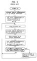
- the estimated temperature ⁇ m is calculated as a value lower than the actual temperature, as shown in FIG. 6.
- the present invention has been made to overcome such problems of the conventional art, and an object of the present invention is to provide a force-feedback input device that can reliably prevent overheating of a torque generator without reducing operation stability of an operating unit.
- the present invention provides a force-feedback input device including an operating unit to be operated by an operator, a position detector for detecting an operating state of the operating unit, a torque generator for applying a force to the operating unit, an ambient-temperature measuring means for measuring the ambient temperature of the torque generator, a controller for controlling the driving of the torque generator according to position information output from the position detector so that a force in accordance with the operating state of the operating unit is applied to the operating unit, and for calculating an estimated temperature of the torque generator on the basis of a current supplied to the torque generator and the ambient temperature from the ambient-temperature measuring means, a storage unit for storing the estimated temperature calculated by the controller, and a power supply for supplying power to the position detector, the torque generator, the controller, and the storage unit.
- the controller compares an estimated temperature immediately before the power supply is stopped, the estimated temperature stored in the storage unit, and the ambient temperature from the ambient-temperature measuring unit, and calculates a new estimated temperature with reference to higher one of the estimated temperature and the ambient temperature.
- the controller reduces the current supplied to the torque generator when the calculated estimated temperature exceeds a predetermined value.
- the controller By thus calculating the estimated temperature of the torque generator by the controller and reducing the current supplied to the torque generator when the calculated estimated temperature exceeds a predetermined value, the amount of heat generated by the torque generator can be limited, and various problems resulting from overheating of the torque generator can be prevented. In addition, since the supply of the driving power to the torque generator is not stopped, and the force application to the operating unit is continued, operation stability of the operating unit can be maintained.
- FIG. 1 is a structural view of a force-feedback input device of this embodiment
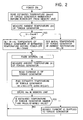
- FIG. 2 is a flowchart showing the procedure for controlling the driving current applied to a torque generator in the force-feedback input device of the embodiment
- FIGS. 3A and 3B are graphs showing the advantages of the force-feedback input device of the embodiment.
- the force-feedback input device of this embodiment mainly includes an operating unit 1 to be operated by an operator, a position detector 2 for detecting the operating state of the operating unit 1, a torque generator 3 for applying a force to the operating unit, a controller 4 for controlling the driving of the torque generator 3 so that a force in accordance with the operating state of the operating unit 1 is applied to the operating unit 1, an ambient thermometer 5 serving as an ambient-temperature measuring means for detecting the ambient temperature of the torque generator 3, a storage unit 6, and a power supply 7 for supplying power to the position detector 2, the torque generator 3, the controller 4, the ambient thermometer 5, and the storage unit 6.
- the operating unit 1 is manually operated by the operator, and, for example, a rotary knob, a swing lever, or a joystick is appropriately used according to the application of the force-feedback input device.
- the position detector 2 converts the amount and direction of operation of the operating unit 1 into the amount of electricity, and outputs the converted amount.
- an encoder or a potentiometer is used.
- the torque generator 3 applies a required force to the operating unit 1, and is, for example, a rotary motor, a linear motor, or a solenoid.
- a required power transmission mechanism is provided between the torque generator 3 and the operating unit 1 to convert the rotational motion of the torque generator 3 into the linear motion and to transmit the motion.
- the ambient thermometer 5 outputs the ambient temperature of the torque generator 3 in the form of the amount of electricity, and is, for example, a thermistor or a ceramic thermometer.
- the ambient thermometer 5 may be attached to a vehicle so as to also function as a thermometer used, for example, to control an air conditioner.
- the storage unit 6 stores an estimated temperature of the torque generator 3 calculated by the controller 4, which will be described later, immediately before the power supply 7 is stopped.
- the storage unit 6 is, for example, a nonvolatile semiconductor memory.
- the controller 4 includes a torque calculator 4a and a temperature calculator 4b, as shown in FIG. 1.
- the torque calculator 4a finds torque information serving as control information for the torque generator 3 on the basis of position information output from the position detector 2, and controls the driving of the torque generator 3 to apply, to the operating unit 1, a force in accordance with the operation.
- the actuator control system, the manual operating unit 3, the actuator 14, and the encoder 25 disclosed in the above publication correspond, respectively, to the torque calculator 4a, the operating unit 1, the torque generator 3, and the position detector 2 in this application.
- the temperature calculator 4b calculates a new estimated temperature of the torque generator 3 on the basis of motor-current information output from the torque calculator 4a, ambient-temperature information output from the ambient thermometer 5, and the estimated temperature immediately before the power stoppage that is read from the storage unit 6.
- the temperature calculator 4b outputs the calculated estimated temperature as motor-temperature information to the torque calculator 4a so as to correct the torque information found by the torque calculator 4a. More specifically, when the new estimated temperature of the torque generator 3 exceeds a predetermined value, the current supplied to the torque generator 3 is reduced to cool the torque generator 3.
- R represents the internal resistance of the torque generator 3
- I represents the current supplied to the torque generator 3
- ⁇ represents the heat transfer rate of the torque generator 3
- ⁇ represents the difference between the temperature of the torque generator 3 and the ambient temperature
- ⁇ represents the heat storage rate of the torque generator 3.
- the initial temperature ⁇ m of the torque generator 3 is set at the estimated temperature ⁇ mold, operations of fetching the ambient temperature ⁇ r from the ambient thermometer 5 and obtaining the motor current I supplied to the torque generator 3 are repeated at fixed intervals of ⁇ t, and an estimated temperature ⁇ m of the torque generator 3 is calculated using the above expression.
- the calculated estimated temperature ⁇ m of the torque generator 3 is stored in the storage unit 6, and it is determined whether the calculated estimated temperature ⁇ m of the torque generator 3 is higher than the predetermined value.
- the calculated estimated temperature ⁇ m of the torque generator 3 is lower than or equal to the predetermined value, the above processes are repeated.
- the calculated estimated temperature ⁇ m exceeds the predetermined value, the current supplied to the torque generator 3 is reduced, and the above processes are then repeated.
- the force-feedback input device having this configuration has advantages equivalent to those of the force-feedback input device previously proposed by the present applicant. Furthermore, the estimated temperature ⁇ m of the torque generator 3 immediately before the power supply 7 is stopped is stored in the storage unit 6, and the controller 4 calculates a new estimated temperature based on higher one of the estimated temperature ⁇ m read from the storage unit 6 and the ambient temperature ⁇ r, when the stopped power supply 7 is restarted. Therefore, as shown in FIGS.
Landscapes
- Engineering & Computer Science (AREA)
- General Engineering & Computer Science (AREA)
- Theoretical Computer Science (AREA)
- Human Computer Interaction (AREA)
- Physics & Mathematics (AREA)
- General Physics & Mathematics (AREA)
- Power Steering Mechanism (AREA)
- Control Of Position Or Direction (AREA)
- Recording Measured Values (AREA)
- Steering Control In Accordance With Driving Conditions (AREA)
Applications Claiming Priority (2)
| Application Number | Priority Date | Filing Date | Title |
|---|---|---|---|
| JP2003076091A JP4268430B2 (ja) | 2003-03-19 | 2003-03-19 | 力覚付与型入力装置 |
| JP2003076091 | 2003-03-19 |
Publications (3)
| Publication Number | Publication Date |
|---|---|
| EP1460521A2 true EP1460521A2 (de) | 2004-09-22 |
| EP1460521A3 EP1460521A3 (de) | 2007-08-15 |
| EP1460521B1 EP1460521B1 (de) | 2017-10-18 |
Family
ID=32821356
Family Applications (1)
| Application Number | Title | Priority Date | Filing Date |
|---|---|---|---|
| EP04005610.3A Expired - Lifetime EP1460521B1 (de) | 2003-03-19 | 2004-03-09 | Eingabevorrichtung mit Kraftrückkopplungsfunktion |
Country Status (3)
| Country | Link |
|---|---|
| US (1) | US7158114B2 (de) |
| EP (1) | EP1460521B1 (de) |
| JP (1) | JP4268430B2 (de) |
Cited By (3)
| Publication number | Priority date | Publication date | Assignee | Title |
|---|---|---|---|---|
| FR2869862A1 (fr) * | 2004-05-06 | 2005-11-11 | Favess Co Ltd | Dispositif formant direction assistee electrique |
| EP1679574A1 (de) * | 2005-01-04 | 2006-07-12 | Hitachi, Ltd. | Steuergerät und Verfahren |
| EP1953912A3 (de) * | 2007-01-31 | 2015-09-16 | Mitsuba Corporation | Verfahren zur Bestimmung einer Spulentemperatur eines Elektromotors |
Families Citing this family (6)
| Publication number | Priority date | Publication date | Assignee | Title |
|---|---|---|---|---|
| JP4209235B2 (ja) * | 2003-03-28 | 2009-01-14 | アルプス電気株式会社 | 力覚付与型入力装置 |
| JP4310127B2 (ja) * | 2003-04-14 | 2009-08-05 | アルプス電気株式会社 | 力覚付与型入力装置 |
| JP4534784B2 (ja) * | 2005-02-15 | 2010-09-01 | 日本精工株式会社 | 電動パワーステアリング装置の制御装置 |
| US7321213B2 (en) * | 2005-07-20 | 2008-01-22 | Asmo Co., Ltd. | Motor controller |
| JP4611870B2 (ja) * | 2005-11-18 | 2011-01-12 | 矢崎総業株式会社 | 車両用表示装置 |
| CN115995355B (zh) * | 2021-10-20 | 2026-02-17 | 歌尔科技有限公司 | 电子设备和电子系统 |
Citations (2)
| Publication number | Priority date | Publication date | Assignee | Title |
|---|---|---|---|---|
| US5559412A (en) | 1991-10-24 | 1996-09-24 | Lex Computer And Management Corporation | Actuator having electronically controllable tactile responsiveness |
| US6162123A (en) | 1997-11-25 | 2000-12-19 | Woolston; Thomas G. | Interactive electronic sword game |
Family Cites Families (6)
| Publication number | Priority date | Publication date | Assignee | Title |
|---|---|---|---|---|
| JPH06197592A (ja) * | 1992-12-25 | 1994-07-15 | Tokai Rika Co Ltd | モータ駆動制御装置 |
| US5446362A (en) * | 1994-06-21 | 1995-08-29 | General Electric Company | Thermal protection for AC traction motors using temperature estimations to calculate torque limits and blower speed requirements |
| US5691898A (en) * | 1995-09-27 | 1997-11-25 | Immersion Human Interface Corp. | Safe and low cost computer peripherals with force feedback for consumer applications |
| JPH1120718A (ja) * | 1997-06-27 | 1999-01-26 | Komatsu Ltd | 電気式パワーステアリング制御装置及びそのモータ電流制御方法 |
| JP2001187268A (ja) * | 2000-11-06 | 2001-07-10 | Mitsui Eng & Shipbuild Co Ltd | ジョイスティックコントロール方法および装置 |
| JP3920559B2 (ja) | 2000-11-10 | 2007-05-30 | アルプス電気株式会社 | 手動入力装置 |
-
2003
- 2003-03-19 JP JP2003076091A patent/JP4268430B2/ja not_active Expired - Fee Related
-
2004
- 2004-03-09 EP EP04005610.3A patent/EP1460521B1/de not_active Expired - Lifetime
- 2004-03-15 US US10/800,609 patent/US7158114B2/en not_active Expired - Lifetime
Patent Citations (2)
| Publication number | Priority date | Publication date | Assignee | Title |
|---|---|---|---|---|
| US5559412A (en) | 1991-10-24 | 1996-09-24 | Lex Computer And Management Corporation | Actuator having electronically controllable tactile responsiveness |
| US6162123A (en) | 1997-11-25 | 2000-12-19 | Woolston; Thomas G. | Interactive electronic sword game |
Cited By (3)
| Publication number | Priority date | Publication date | Assignee | Title |
|---|---|---|---|---|
| FR2869862A1 (fr) * | 2004-05-06 | 2005-11-11 | Favess Co Ltd | Dispositif formant direction assistee electrique |
| EP1679574A1 (de) * | 2005-01-04 | 2006-07-12 | Hitachi, Ltd. | Steuergerät und Verfahren |
| EP1953912A3 (de) * | 2007-01-31 | 2015-09-16 | Mitsuba Corporation | Verfahren zur Bestimmung einer Spulentemperatur eines Elektromotors |
Also Published As
| Publication number | Publication date |
|---|---|
| EP1460521A3 (de) | 2007-08-15 |
| JP4268430B2 (ja) | 2009-05-27 |
| US20040195987A1 (en) | 2004-10-07 |
| JP2004287583A (ja) | 2004-10-14 |
| EP1460521B1 (de) | 2017-10-18 |
| US7158114B2 (en) | 2007-01-02 |
Similar Documents
| Publication | Publication Date | Title |
|---|---|---|
| US6902028B2 (en) | Electric power steering control system | |
| KR100563727B1 (ko) | 전동 파워 스티어링 장치 | |
| US7158114B2 (en) | Force-feedback input device | |
| CA2683249A1 (en) | Apparatus and method for control of a thermostat | |
| EP2482446B1 (de) | Verfahren und Systeme mit elektrischen Maschinensteuerungen | |
| EP2881305A2 (de) | Motorgetriebene Servolenkung und Verfahren zu ihrer Ansteuerung | |
| US7322438B2 (en) | Control apparatus for an electrically driven power steering | |
| JP5163251B2 (ja) | 電動パワーステアリング装置の制御装置 | |
| EP0573658A1 (de) | Verfahren zur verhinderung der entmagnetisierung und regelung für einen elektrischen motor | |
| JP2008245473A (ja) | モータ制御方法及びモータ制御装置 | |
| JP2006115553A (ja) | 電動パワーステアリング装置における電動モータの温度推定装置 | |
| JP4720965B2 (ja) | 電動パワーステアリング装置 | |
| JP2007112188A (ja) | 電動パワーステアリング装置 | |
| US6959232B2 (en) | Force sense imparting type input apparatus | |
| JP2002234456A (ja) | 電動パワーステアリング装置 | |
| JP2002308134A (ja) | 運転操作装置 | |
| JP4792820B2 (ja) | 電動パワーステアリング装置の制御装置 | |
| JP6205208B2 (ja) | 過熱防止装置、過熱防止方法及び過熱防止プログラム | |
| JP2022167646A (ja) | 駆動部材制御装置 | |
| CN120196147A (zh) | 用于对电系统进行温度监控的方法 | |
| GB2592598A8 (en) | Electric power steering system | |
| JP2022167646A5 (de) | ||
| JP2023077656A (ja) | ペダル装置 | |
| JP2005115546A (ja) | モータ制御装置およびモータ制御方法 | |
| JP2002370659A (ja) | 電動パワーステアリング装置 |
Legal Events
| Date | Code | Title | Description |
|---|---|---|---|
| PUAI | Public reference made under article 153(3) epc to a published international application that has entered the european phase |
Free format text: ORIGINAL CODE: 0009012 |
|
| AK | Designated contracting states |
Kind code of ref document: A2 Designated state(s): AT BE BG CH CY CZ DE DK EE ES FI FR GB GR HU IE IT LI LU MC NL PL PT RO SE SI SK TR |
|
| AX | Request for extension of the european patent |
Extension state: AL LT LV MK |
|
| PUAL | Search report despatched |
Free format text: ORIGINAL CODE: 0009013 |
|
| AK | Designated contracting states |
Kind code of ref document: A3 Designated state(s): AT BE BG CH CY CZ DE DK EE ES FI FR GB GR HU IE IT LI LU MC NL PL PT RO SE SI SK TR |
|
| AX | Request for extension of the european patent |
Extension state: AL LT LV MK |
|
| 17P | Request for examination filed |
Effective date: 20070906 |
|
| AKX | Designation fees paid |
Designated state(s): DE FR GB |
|
| 17Q | First examination report despatched |
Effective date: 20110818 |
|
| REG | Reference to a national code |
Ref country code: DE Ref legal event code: R079 Ref document number: 602004051920 Country of ref document: DE Free format text: PREVIOUS MAIN CLASS: G06F0003000000 Ipc: G06F0003010000 |
|
| RIC1 | Information provided on ipc code assigned before grant |
Ipc: G06F 3/01 20060101AFI20170411BHEP Ipc: G06F 1/20 20060101ALI20170411BHEP |
|
| GRAP | Despatch of communication of intention to grant a patent |
Free format text: ORIGINAL CODE: EPIDOSNIGR1 |
|
| INTG | Intention to grant announced |
Effective date: 20170614 |
|
| GRAS | Grant fee paid |
Free format text: ORIGINAL CODE: EPIDOSNIGR3 |
|
| GRAA | (expected) grant |
Free format text: ORIGINAL CODE: 0009210 |
|
| AK | Designated contracting states |
Kind code of ref document: B1 Designated state(s): DE FR GB |
|
| REG | Reference to a national code |
Ref country code: GB Ref legal event code: FG4D |
|
| REG | Reference to a national code |
Ref country code: DE Ref legal event code: R081 Ref document number: 602004051920 Country of ref document: DE Owner name: ALPS ALPINE CO., LTD., JP Free format text: FORMER OWNER: ALPS ELECTRIC CO., LTD., TOKIO/TOKYO, JP |
|
| REG | Reference to a national code |
Ref country code: DE Ref legal event code: R096 Ref document number: 602004051920 Country of ref document: DE |
|
| REG | Reference to a national code |
Ref country code: FR Ref legal event code: PLFP Year of fee payment: 15 |
|
| REG | Reference to a national code |
Ref country code: DE Ref legal event code: R097 Ref document number: 602004051920 Country of ref document: DE |
|
| PLBE | No opposition filed within time limit |
Free format text: ORIGINAL CODE: 0009261 |
|
| STAA | Information on the status of an ep patent application or granted ep patent |
Free format text: STATUS: NO OPPOSITION FILED WITHIN TIME LIMIT |
|
| 26N | No opposition filed |
Effective date: 20180719 |
|
| REG | Reference to a national code |
Ref country code: DE Ref legal event code: R082 Ref document number: 602004051920 Country of ref document: DE Representative=s name: SCHMITT-NILSON SCHRAUD WAIBEL WOHLFROM PATENTA, DE Ref country code: DE Ref legal event code: R081 Ref document number: 602004051920 Country of ref document: DE Owner name: ALPS ALPINE CO., LTD., JP Free format text: FORMER OWNER: ALPS ELECTRIC CO., LTD., TOKYO, JP |
|
| PGFP | Annual fee paid to national office [announced via postgrant information from national office to epo] |
Ref country code: DE Payment date: 20200320 Year of fee payment: 17 Ref country code: GB Payment date: 20200323 Year of fee payment: 17 |
|
| PGFP | Annual fee paid to national office [announced via postgrant information from national office to epo] |
Ref country code: FR Payment date: 20200319 Year of fee payment: 17 |
|
| REG | Reference to a national code |
Ref country code: DE Ref legal event code: R119 Ref document number: 602004051920 Country of ref document: DE |
|
| GBPC | Gb: european patent ceased through non-payment of renewal fee |
Effective date: 20210309 |
|
| PG25 | Lapsed in a contracting state [announced via postgrant information from national office to epo] |
Ref country code: FR Free format text: LAPSE BECAUSE OF NON-PAYMENT OF DUE FEES Effective date: 20210331 Ref country code: GB Free format text: LAPSE BECAUSE OF NON-PAYMENT OF DUE FEES Effective date: 20210309 Ref country code: DE Free format text: LAPSE BECAUSE OF NON-PAYMENT OF DUE FEES Effective date: 20211001 |