EP1460668A1 - Groupe de connection préassemblé - Google Patents
Groupe de connection préassemblé Download PDFInfo
- Publication number
- EP1460668A1 EP1460668A1 EP04006424A EP04006424A EP1460668A1 EP 1460668 A1 EP1460668 A1 EP 1460668A1 EP 04006424 A EP04006424 A EP 04006424A EP 04006424 A EP04006424 A EP 04006424A EP 1460668 A1 EP1460668 A1 EP 1460668A1
- Authority
- EP
- European Patent Office
- Prior art keywords
- connection
- contact
- heating device
- connection module
- heating
- Prior art date
- Legal status (The legal status is an assumption and is not a legal conclusion. Google has not performed a legal analysis and makes no representation as to the accuracy of the status listed.)
- Withdrawn
Links
Images
Classifications
-
- H—ELECTRICITY
- H05—ELECTRIC TECHNIQUES NOT OTHERWISE PROVIDED FOR
- H05B—ELECTRIC HEATING; ELECTRIC LIGHT SOURCES NOT OTHERWISE PROVIDED FOR; CIRCUIT ARRANGEMENTS FOR ELECTRIC LIGHT SOURCES, IN GENERAL
- H05B1/00—Details of electric heating devices
- H05B1/02—Automatic switching arrangements specially adapted to apparatus ; Control of heating devices
- H05B1/0202—Switches
- H05B1/0216—Switches actuated by the expansion of a solid element, e.g. wire or rod
-
- H—ELECTRICITY
- H01—ELECTRIC ELEMENTS
- H01H—ELECTRIC SWITCHES; RELAYS; SELECTORS; EMERGENCY PROTECTIVE DEVICES
- H01H37/00—Thermally-actuated switches
- H01H37/74—Switches in which only the opening movement or only the closing movement of a contact is effected by heating or cooling
- H01H37/76—Contact member actuated by melting of fusible material, actuated due to burning of combustible material or due to explosion of explosive material
- H01H37/764—Contact member actuated by melting of fusible material, actuated due to burning of combustible material or due to explosion of explosive material in which contacts are held closed by a thermal pellet
-
- H—ELECTRICITY
- H05—ELECTRIC TECHNIQUES NOT OTHERWISE PROVIDED FOR
- H05B—ELECTRIC HEATING; ELECTRIC LIGHT SOURCES NOT OTHERWISE PROVIDED FOR; CIRCUIT ARRANGEMENTS FOR ELECTRIC LIGHT SOURCES, IN GENERAL
- H05B3/00—Ohmic-resistance heating
- H05B3/02—Details
- H05B3/06—Heater elements structurally combined with coupling elements or holders
Definitions
- the present invention relates to a connection module for electrical heating devices, in particular for instantaneous water heaters, and to a heating device equipped therewith according to claim 10.
- Electric heaters are used, for example, in the form of a continuous-flow heater for heating a working fluid, e.g. B. of water, used in a machine such as a washing machine or dishwasher.
- a working fluid e.g. B. of water
- the at least one heating conductor of the heating device which is made of a material whose electrical resistance value is sufficient for converting electrical energy into heat, can be spirally wound around a flow tube for the working fluid and, depending on the one used Heating conductor, are attached to the flow tube in a suitable manner.
- the two ends of the heating conductor are prepared in such a way that after installation of the heating device in the machine, a connection can be made to a corresponding power source via suitable connection elements.
- the heating device In order to prevent the heating device from running dry accidentally, i.e. When the heating device is put into operation without a working fluid flowing through the flow tube, which can dissipate the heat generated by the heating conductor, to prevent damage to the working machine, such heating devices are equipped with excess temperature safeguards. In order to achieve an overall compact structure, the aim is to accommodate the overtemperature protection in the area of the connection ends of the heating conductor.
- connection end of the heating conductor to the insulating body by means of a welding process is a labor-intensive measure which leads to considerable costs.
- additional auxiliary or straightening tools are required to hold the insulating body and the connection end in the intended position during the welding process. In other words, this solution is expensive, which is particularly disadvantageous for components which are subject to considerable cost pressure.
- connection module of the type mentioned at the outset, which enables a heating conductor of an electrical heating device to be connected to a power source in a simple and therefore inexpensive manner.
- a heating device is to be provided which uses such a connection module.
- connection module By pre-assembling the connection module and by the contact or system contact between the connection ends of the heating conductor and the contacting elements, it is possible to easily connect the heating device to a power source during assembly. Due to the contact between the connection module and the connection ends of the heating conductor by means of a simple touch or contact, no protruding connection ends of the heating conductor and / or complicated movements when attaching the connection module are required, but a simple movement in the radial direction of the flow tube or perpendicular to the laying plane of the heating conductor is sufficient , There is also no need to overcome mechanical resistances such as with flags and the like.
- the heating device with the flow tube or with a support plate, on which the heating conductor is laid in one plane can be manufactured separately from the connection module in a separate manufacturing process and then the two modules, ie the heating device as heating module and the connection module, can be easily connected to one another get connected. Furthermore, there is the possibility of replacing a defective connection module in a simple manner, which is not possible with the solution of the prior art described above, since the connection end can no longer be separated from the insulating body as a result of the welding process used.
- connection module can be connected permanently to the heating device, if necessary by means of suitable fastening elements, after it has been placed on the heating device in order to make contact between the connection ends of the heating conductor and the two contacting elements of the connection module. It is also possible that the connection module is also detachably attached to the heating device by means of suitable fastening elements, such as clips, clamps, etc. For example, lugs can be attached or formed on the carrier unit for this purpose, which are connected to the heating device via clamping brackets.
- connection module After the connection module has been placed on the heating device, the connection module is thereby pulled against the heating device, so that the contact surface of the first contacting element, which is preferably present, and the contact surface, if any, of the second contacting element comes into flat contact with the connection elements of the heating conductor.
- connection module can be attached by having through openings or continuous recesses by means of which the connection module can be pushed onto the bolts. Then nuts can be screwed onto the bolts so that the connection module is held on the heating device. If the bolts do not have a thread, the recesses can allow latching lugs, clip-like elements etc. for releasable or non-releasable latching of the connection module on the heating device.
- the first and / or the second contacting element resiliently in the contacting direction the carrier unit is held. If the connection module is placed on the heating device, the first and / or the second contacting element are urged against the respective connection end of the heating conductor of the heating device as a result of their elastically resilient design in the contacting direction. If the first and / or the second contacting element protrude beyond the outer contour of the carrier unit in the non-assembled state of the connection assembly, a preload is also applied to the first and / or the second contacting element when the connection assembly is placed on the heating device.
- This bias can also be supported in such a way that on the first and / or the second contacting element, a spring such.
- a spring such.
- a leaf spring acts or the first and / or the second contacting element have an impressed internal stress.
- the first and / or the second contacting element are prestressed in the contact direction via an electrically conductive, current-carrying plastic.
- a flat contact of the first and / or the second contacting element ensures that a sufficient electrical connection or contact is made possible between the connection module and thus the power source and the heating conductor.
- the temperature-dependent overload protection there is in principle the possibility of attaching it to any location in the heating device, as long as it is ensured that the current flow is interrupted when the overload protection is triggered. There is also the possibility that the temperature-dependent overload protection is provided on the connection module.
- a particularly compact and easy-to-assemble design is realized in that the temperature-dependent overload protection is connected to the current flow between the contact surface of the first contacting element and the connection section.
- the temperature-dependent overload protection can also be used in the current flow between the second contacting element and the connection section can be provided.
- a simple and reliable temperature-dependent overload protection can consist of a prestressed spring strip, which is connected at one end to the connection section and at its other end via a connecting means to the contact surface of the first contacting element in such a way that when a predetermined temperature range is reached, preferably one predetermined limit temperature, the connecting means releases the prestressed spring strip and lifts it from the contact surface.
- Any material can be used as the connecting means, for example a suitable low-melting solder, which is dimensioned for the respective application.
- a contact material softening or melting at a defined temperature or in a narrow temperature range can also be used.
- the temperature at the connecting means remains below the intended limit temperature or the intended temperature range.
- a certain temperature safety margin must be taken into account so that the operational temperature change stress does not lead to premature detachment of the pretensioned spring strip as a result of the constantly acting tensile stress or tensile force.
- heating occurs in the area of the connecting means, which "softens" the connecting means in such a way that the tensile force or tensile stress acting on the solder point is sufficient to separate the spring strip from the solder joint.
- the spring strip can therefore, as a result of its pre-stressed on it, be it by means of a leaf spring or by means of an impressed internal stress, detach from the contact surface of the first contacting element and thus interrupt the electrical contact between the power source and the heating conductor.
- the separation gap that forms here must be so large that the arc cannot be ignited again.
- additional spark extinguishing measures can be used to extinguish the resulting arc depending on the operating voltage.
- the second contacting element can also be biased in the contact direction via an electrically conductive, current-carrying plastic.
- the temperature-dependent overload protection can also be formed in that a movement element, preferably extending perpendicular to the longitudinal axis of the heating device, is provided, which is in contact at one end with the first contacting element and at its other end via a deformation element which is exposed to heat Can change shape, is in contact with the heating device, the length of the movement element is dimensioned such that, during normal operation of the electrical heating device, the first contacting element is in electrical connection with the associated connection element of the connection section or the movement element is in electrical connection with the first contacting element urges to the associated connection element of the connection section.
- the deformation element can be a solder pot, in which the movement element is partially immersed and which is filled with a solder, which softens when a predetermined limit temperature is exceeded, so that the movement element can further immerse into the solder pot.
- the movement element can in turn be a ceramic rod or another element that is electrically insulating and preferably poorly heat-conducting.
- the second Contacting element in the assembled state of the connection module on the heating device under prestress on the heating conductor, in particular on the connection end of the heating conductor.
- the second contacting element can be acted upon by a leaf spring that prestresses in the direction of contact with the heating conductor.
- the second contact element is biased in the direction of contact with the heating conductor by an internal stress impressed on it.
- a measuring unit can also be provided, which is used to control the heating device.
- This measuring unit can be provided separately from the carrier unit, but should preferably be arranged on the carrier unit. There is the possibility here that the measuring unit is formed in one piece with the carrier unit. Likewise, the measuring unit can preferably be reversibly attachable to the carrier unit. Both the first and the second alternative again allow a simple assembly process, since the connection module can be preassembled with the measuring unit.
- the measuring unit can be constructed differently.
- the measuring unit contains a temperature measuring element and a contact element, preferably biased in the contact direction, which can be connected to a control device for the heating device via a connecting section of the measuring unit.
- the temperature detection element is electrically insulated from the surface of the heating device and from the heating conductor. The latter is particularly necessary when the flow tube or the support plate for the heating conductor is grounded.
- an NTC sensor that is elastically resilient in the contact direction can be provided as the temperature measuring element.
- the temperature measuring element is a glass-encapsulated NTC pill with a sleeve made of a good heat-conducting material.
- connection section has an electrical plug-in device, in particular a plug-in lug, for each connection.
- an electrical plug-in device in particular a plug-in lug
- the carrier unit can consist of any temperature-resistant, electrically insulating material.
- a temperature-resistant plastic or ceramic is preferably selected for the carrier unit.
- the carrier unit can be securely attached to the heating device, it is furthermore advantageous if the carrier unit is provided on its side facing the heating device or on the side that comes into contact with the heating device with an outer contour that is complementary to the outer contour of the heating device is.
- connection module According to the heating device, the above object is achieved by the features of claim 7. Claims 8 to 10 contain advantageous refinements for this.
- the connection module according to the invention represents an advantageous solution.
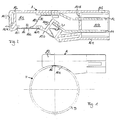
- connection assembly A is used in a continuous-flow heater H for heating a medium, such as the washing water for a dishwasher, which has a flow tube D made of a good heat-conducting but corrosion-resistant material with an essentially circular cross section and one which is not heating conductor shown further comprises an electrical resistance material.
- the heating conductor forming a heating loop is helically wound around the flow tube D in such a way that it extends approximately over the entire axial length of the flow tube D.
- the two connection ends of the heating conductor, also not shown, which are arranged one behind the other in the circumferential direction, are located in the vicinity of one end of the flow tube D, whereas the outermost point of the loop is arranged at the other end of the tube D.
- heating conductor Between the heating conductor and the outer surface of the flow tube D there is also provided an electrically insulating, but good heat-conducting layer or film, which is also not shown and which electrically insulates the flow tube D and thus the medium to be heated from the heating conductor.
- the heating conductor is applied to the insulating layer in thick-film technology.
- the connection module A has a cuboid housing 10, which forms a carrier unit and which is made of a heat-resistant and electrically insulating material, preferably of a plastic having such properties.
- the housing 10 has on its lower left outside, i.e. on the outside coming into contact with the heating conductor or the flow tube D in the assembled state, a circular segment-shaped contact section 10a, the contour of which corresponds to or is complementary to the outer contour of the flow tube D, as can be seen in particular from FIG. 1.
- the housing 10 is provided with a first and a second cavity 10b and 10c, which are separated from each other by a vertical wall 10d which extends from the lower outer wall 10e to the upper outer wall 10f. It should also be noted that the remaining outer contours of the housing 10 of the connection module A can be designed in accordance with the further requirements.
- the first cavity 10b forms a connection section for connecting the connection assembly A to a power source, not shown, whereas the second cavity 10c is a contacting section for contacting the connection ends of the heating conductor.
- the first cavity 10b which is open to the right, two flat plug contacts or plug tabs 12, 14 are arranged one above the other, onto each of which a connecting line to the power source can be pushed.
- the two plug contacts 12, 14 have a width that is much larger than the height of the contacts 12, 14.
- the axial length is of the two plug contacts 12, 14 in the first cavity 10b is shorter than the axial length of the first cavity 10b.
- the two plug contacts 12, 14 penetrate the vertical wall 10d and extend into the second cavity 10c.
- the upper plug contact 12 is attached to the inside of the upper housing wall 10f by a suitable fastening means, such as a rivet.
- the lower plug contact 14 is attached to a wall extension 10g projecting from the contact section 10a of the housing 10 into the interior of the second cavity 10c, for example likewise by means of a rivet.
- a receptacle for a contact element 16 is provided to the left of the wall extension 10g.
- the receptacle is formed by two lugs 10h, 10i, of which one lug 10h extends from the wall extension 10g to the left and the other from the left end 10j of the housing 10 to the right, in each case parallel to the upper housing wall 10f.
- the two lugs 10h, 10i do not protrude beyond the contour of the contact section 10a of the housing 10, but protrude into the second cavity 10c.
- a contact element or a first contacting element 16 is provided on their downward or outward-pointing lower nose surfaces, which is pulled into the pockets 10i, 10h and held there by a tensile force as a result of the spring force of a spring strip 18 explained in more detail below.
- the spring strip 18 having the shape of an inverted letter "Z".
- One or the lower end of the spring strip 18 is fastened to the contact element by means of a solder material, preferably in the form of a solder point, whereas the other or upper end on the inward-facing side of the upper plug contact 12, for example by means of the upper plug contact on the upper housing wall 10f fastening rivet is attached.
- the solder material used to attach the lower end of the spring strip 18 to the contact element 16 is selected such that when a predetermined temperature range, preferably a predetermined limit temperature, the solder material becomes soft and the spring strip 18 can detach from the contact element 16.
- the spring strip 18 is preloaded such that it pivots into the interior of the second cavity 10c when it is not attached to the contact element 16. If the solder material between the lower end of the spring strip 18 and the contact element 16 becomes soft as a result of reaching the predetermined temperature, this lower end of the spring strip 18 can detach from the contact element 16 and thus interrupt the current supply to the heating conductor.
- the lower plug contact 14 is attached to the end of the wall extension 10g which projects furthest into the second cavity 10c.
- a contact spring or a second contact element 21 is attached, which has the shape of a letter "M" rotated by 90 ° to the left.
- the axial length of the contact spring 21, i.e. dimension the length of the contact spring 21 in the direction of the contact section 10a such that it protrudes downward over the arcuate contour of the contact section 10a FIG. 1 shows the dimension of the protrusion, based on the flow tube D).
- connection module A If the connection module A is placed on the flow tube D, the contact spring 21 is moved inwards, i.e. moved into the interior of the second cavity 10c. As a result of their spring characteristics, the lower end of the contact spring 21 is biased against the associated connection end of the heating conductor. At this lower end, the contact spring 21 can be provided with a widening which allows reliable contacting with the connection end of the heating conductor.
- the plug contacts 12, 14, the contact element 16 and the contact spring 21 are made of a material with good electrical conductivity, preferably copper or a copper alloy. Furthermore, there is electrically conductive contact between the plug contacts 12, 14 and the contact element 16 or the contact spring 21, so that a current from the current source via the plug contact 12, the spring strip 18 and the contact element 16 on the one hand and the plug contact 14 and the contact spring 21 on the other hand can flow to or from the heating conductor.
- connection module A To attach the connection module A to the flow pipe D or to the heating conductor, the connection module A is placed on the flow pipe D. As a result, both the contact element 16 and the contact spring 21 pushed into the interior of the second cavity 10c of the housing 10. As a result of the elastic design or elastic attachment of the contact element 16 and the contact spring 21, these then bear against the respective connection ends of the heating conductor under pre-tension.
- the connection assembly A can be attached to the flow tube D by means of clips or clamps or the like, for example, wherein the chamber 10k provided on the left front end of the housing 10 can be used.
- connection assembly A can be removed from the flow tube D without loosening the clamps or the like and can be exchanged for a new connection assembly.
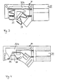
- FIGS. 3 and 4 show two embodiments for a measuring unit M, both of which are constructed in a similar manner to the connection module A shown in FIGS. 1 and 2. Therefore, only the differences between the measuring units M and the connection module A will be discussed below received. It should also be noted that the same reference numerals have been used for the two measuring units M in FIGS. 3 and 4 for geometrically identical or similar and for functionally identical or functionally similar components.
- the measuring unit M shown in FIG. 3 differs from the connection module A in that a temperature measuring element 32 in the form of an NTC pill is fitted in the contacting section 30b of the housing 30 instead of the first contacting element 16.
- a temperature measuring element 32 in the form of an NTC pill is fitted in the contacting section 30b of the housing 30 instead of the first contacting element 16.
- FIG 4 shows the second embodiment for the measuring unit M, in which instead of the first contact element and the second contact element a glass-encapsulated NTC sensor 34 with a copper sleeve is provided.
- This temperature measuring element 34 is also elastically pretensioned in the direction of contact to the flow tube D to the contact surface on the flow tube D.
- the measuring unit M can be connected in one piece to the carrier unit 10. There is also the possibility that the measuring unit M is connected to the carrier unit 10 by a screwing process, by a clip-in process, etc.
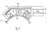
- connection module A shows a further embodiment of the connection module A according to the invention.
- the overload protection device 20 has a movement element 42 in the form of a ceramic rod, which is in contact with the first contacting element 16 at one end 42a when the overload protection device 20 is not triggered.
- the movement element 42 is received in a solder pot 44 in such a way that the movement element 42 is only partially immersed in the solder pot 44.
- the length of the movement element 42 which extends essentially perpendicular to the central longitudinal axis of the heating device H and thus also essentially perpendicular to the first contacting element 16, is dimensioned such that in normal operation, ie in the trouble-free operation of the heating device, the first contacting element 16 with the Corresponding connection element 12 of the connection section 10b is in an electrically conductive connection and the solder pot 44 bears against the heating device, the first contacting element 16 being able to be pressed against the connection element 12 of the connection section 10b with contact pressure.
- the solder heats up in the solder pot 44, so that the movement element 42 as a result of the force of gravity acting on the movement element 42 and a spring tension possibly impressed on the first contacting element 16 the moving element 42 is further immersed in the solder pot 44, as shown in FIG. 5.
- This enables the first contacting element 16 to separate from the electrical contact with the connection element 12 of the connection section 10b.
- the length of the movement path for the movement element 42 is dimensioned such that a spark train is not possible. If necessary, the movement element 42 dips into the solder pot 44 to such an extent that it also detaches from the contacting element 16, as shown in FIG. 5.
Landscapes
- Chemical & Material Sciences (AREA)
- Engineering & Computer Science (AREA)
- Combustion & Propulsion (AREA)
- Resistance Heating (AREA)
Applications Claiming Priority (2)
| Application Number | Priority Date | Filing Date | Title |
|---|---|---|---|
| DE10313861 | 2003-03-21 | ||
| DE2003113861 DE10313861A1 (de) | 2003-03-21 | 2003-03-21 | Vormontierte Anschlussbaugruppe |
Publications (1)
| Publication Number | Publication Date |
|---|---|
| EP1460668A1 true EP1460668A1 (fr) | 2004-09-22 |
Family
ID=32798135
Family Applications (1)
| Application Number | Title | Priority Date | Filing Date |
|---|---|---|---|
| EP04006424A Withdrawn EP1460668A1 (fr) | 2003-03-21 | 2004-03-17 | Groupe de connection préassemblé |
Country Status (2)
| Country | Link |
|---|---|
| EP (1) | EP1460668A1 (fr) |
| DE (1) | DE10313861A1 (fr) |
Citations (5)
| Publication number | Priority date | Publication date | Assignee | Title |
|---|---|---|---|---|
| US4307370A (en) * | 1978-06-15 | 1981-12-22 | Inter Control Hermann Kohler Elektrik Gmbh & Co. Kg | Heat sensitive circuit breaker employing meltable material |
| US5434388A (en) * | 1992-10-07 | 1995-07-18 | E.G.O. Elektro-Gerate Blanc U. Fischer | Electrical heater for media, particularly flow heater |
| EP0727799A2 (fr) * | 1995-02-18 | 1996-08-21 | E.G.O. Elektro-Geräte Blanc und Fischer GmbH & Co. KG | Protection contre suréchauffement d'un dispositif de chauffage électrique |
| GB2315366A (en) * | 1996-07-12 | 1998-01-28 | Otter Controls Ltd | Thermal controls for liquid heating vessels |
| US6250259B1 (en) * | 1998-11-17 | 2001-06-26 | Braun Gmbh | Flow-through heater for heating water |
-
2003
- 2003-03-21 DE DE2003113861 patent/DE10313861A1/de not_active Withdrawn
-
2004
- 2004-03-17 EP EP04006424A patent/EP1460668A1/fr not_active Withdrawn
Patent Citations (5)
| Publication number | Priority date | Publication date | Assignee | Title |
|---|---|---|---|---|
| US4307370A (en) * | 1978-06-15 | 1981-12-22 | Inter Control Hermann Kohler Elektrik Gmbh & Co. Kg | Heat sensitive circuit breaker employing meltable material |
| US5434388A (en) * | 1992-10-07 | 1995-07-18 | E.G.O. Elektro-Gerate Blanc U. Fischer | Electrical heater for media, particularly flow heater |
| EP0727799A2 (fr) * | 1995-02-18 | 1996-08-21 | E.G.O. Elektro-Geräte Blanc und Fischer GmbH & Co. KG | Protection contre suréchauffement d'un dispositif de chauffage électrique |
| GB2315366A (en) * | 1996-07-12 | 1998-01-28 | Otter Controls Ltd | Thermal controls for liquid heating vessels |
| US6250259B1 (en) * | 1998-11-17 | 2001-06-26 | Braun Gmbh | Flow-through heater for heating water |
Also Published As
| Publication number | Publication date |
|---|---|
| DE10313861A1 (de) | 2004-09-30 |
Similar Documents
| Publication | Publication Date | Title |
|---|---|---|
| EP2846344B1 (fr) | Commutateur thermique | |
| EP1152639B1 (fr) | Unité de chauffage électrique, particulièrement destiné à des milieux liquides | |
| DE19941190B4 (de) | Wärmeschutzsicherung | |
| EP3208812B1 (fr) | Élément de protection contre les surtensions | |
| EP0591755A1 (fr) | Radiateur électrique pour fluides notamment pour dispositifs de chauffage en continu | |
| DE102008022794A1 (de) | Elektrisches Schutzbauelement mit Kurzschlusseinrichtung | |
| EP0951040B2 (fr) | Interrupteur à commande thermique | |
| DE10044081A1 (de) | Überlastschutz | |
| EP1849172A2 (fr) | Dispositif pour lancer un element chauffant dans une automobile | |
| DE102008036672B3 (de) | Elektrische Schmelzsicherung | |
| DE102015110417A1 (de) | Kontaktelement und damit ausgestattete Stromschiene oder Leiterplatte | |
| EP0951041B1 (fr) | Interrupteur à commande thermique | |
| DE69505884T2 (de) | Geräte mit Widerstandselemeten und Temperaturschutzvorrichtung zum Gebrauch dafür | |
| EP0806783A2 (fr) | Contact électrique | |
| EP2506281B1 (fr) | Commutateur thermodépendant avec résistance protectrice | |
| EP1460668A1 (fr) | Groupe de connection préassemblé | |
| DE102004015394A1 (de) | Schalter mit isolierter Positioniertasche für Heizwiderstand | |
| EP1810308B1 (fr) | Declencheur thermique | |
| DE60005713T2 (de) | Sicherheitsvorrichtung zur temperaturüberwachung für elektrische anlage mit verbindungen | |
| DE69129468T2 (de) | Elektrischer rohrheizkörper mit einer temperaturkontrolleinrichtung | |
| DE19953954B4 (de) | Anschlußklemme | |
| DE2531291B2 (de) | Elektrischer Schichtwiderstand mit Schmelzsicherung für stehenden Einbau in gedruckte Schaltungen | |
| WO2013139573A1 (fr) | Système de contact et appareil de coupure électrique | |
| EP0557753A2 (fr) | Dispositif de protection d'un appareil | |
| DE19620340C1 (de) | Überspannungs - Schutzstecker |
Legal Events
| Date | Code | Title | Description |
|---|---|---|---|
| PUAI | Public reference made under article 153(3) epc to a published international application that has entered the european phase |
Free format text: ORIGINAL CODE: 0009012 |
|
| AK | Designated contracting states |
Kind code of ref document: A1 Designated state(s): AT BE BG CH CY CZ DE DK EE ES FI FR GB GR HU IE IT LI LU MC NL PL PT RO SE SI SK TR |
|
| AX | Request for extension of the european patent |
Extension state: AL LT LV MK |
|
| RAP1 | Party data changed (applicant data changed or rights of an application transferred) |
Owner name: BLECKMANN GMBH & CO. KG |
|
| RIN1 | Information on inventor provided before grant (corrected) |
Inventor name: DE VRIES, GERHARDUS Inventor name: ZINNER, GEROLD |
|
| 17P | Request for examination filed |
Effective date: 20050322 |
|
| D17P | Request for examination filed (deleted) | ||
| AKX | Designation fees paid | ||
| REG | Reference to a national code |
Ref country code: DE Ref legal event code: 8566 |
|
| STAA | Information on the status of an ep patent application or granted ep patent |
Free format text: STATUS: THE APPLICATION IS DEEMED TO BE WITHDRAWN |
|
| 18D | Application deemed to be withdrawn |
Effective date: 20050322 |