EP1460772A2 - Système de télécommunication à spectre étalé à bandes multiples et à modes multiples - Google Patents
Système de télécommunication à spectre étalé à bandes multiples et à modes multiples Download PDFInfo
- Publication number
- EP1460772A2 EP1460772A2 EP04013982A EP04013982A EP1460772A2 EP 1460772 A2 EP1460772 A2 EP 1460772A2 EP 04013982 A EP04013982 A EP 04013982A EP 04013982 A EP04013982 A EP 04013982A EP 1460772 A2 EP1460772 A2 EP 1460772A2
- Authority
- EP
- European Patent Office
- Prior art keywords
- spread spectrum
- frequency
- frequency band
- carrier frequency
- access network
- Prior art date
- Legal status (The legal status is an assumption and is not a legal conclusion. Google has not performed a legal analysis and makes no representation as to the accuracy of the status listed.)
- Withdrawn
Links
Images










Classifications
-
- H—ELECTRICITY
- H04—ELECTRIC COMMUNICATION TECHNIQUE
- H04K—SECRET COMMUNICATION; JAMMING OF COMMUNICATION
- H04K1/00—Secret communication
-
- H—ELECTRICITY
- H04—ELECTRIC COMMUNICATION TECHNIQUE
- H04B—TRANSMISSION
- H04B1/00—Details of transmission systems, not covered by a single one of groups H04B3/00 - H04B13/00; Details of transmission systems not characterised by the medium used for transmission
- H04B1/38—Transceivers, i.e. devices in which transmitter and receiver form a structural unit and in which at least one part is used for functions of transmitting and receiving
- H04B1/40—Circuits
- H04B1/403—Circuits using the same oscillator for generating both the transmitter frequency and the receiver local oscillator frequency
- H04B1/406—Circuits using the same oscillator for generating both the transmitter frequency and the receiver local oscillator frequency with more than one transmission mode, e.g. analog and digital modes
-
- H—ELECTRICITY
- H04—ELECTRIC COMMUNICATION TECHNIQUE
- H04B—TRANSMISSION
- H04B1/00—Details of transmission systems, not covered by a single one of groups H04B3/00 - H04B13/00; Details of transmission systems not characterised by the medium used for transmission
- H04B1/005—Details of transmission systems, not covered by a single one of groups H04B3/00 - H04B13/00; Details of transmission systems not characterised by the medium used for transmission adapting radio receivers, transmitters andtransceivers for operation on two or more bands, i.e. frequency ranges
-
- H—ELECTRICITY
- H04—ELECTRIC COMMUNICATION TECHNIQUE
- H04B—TRANSMISSION
- H04B1/00—Details of transmission systems, not covered by a single one of groups H04B3/00 - H04B13/00; Details of transmission systems not characterised by the medium used for transmission
- H04B1/005—Details of transmission systems, not covered by a single one of groups H04B3/00 - H04B13/00; Details of transmission systems not characterised by the medium used for transmission adapting radio receivers, transmitters andtransceivers for operation on two or more bands, i.e. frequency ranges
- H04B1/0053—Details of transmission systems, not covered by a single one of groups H04B3/00 - H04B13/00; Details of transmission systems not characterised by the medium used for transmission adapting radio receivers, transmitters andtransceivers for operation on two or more bands, i.e. frequency ranges with common antenna for more than one band
- H04B1/0057—Details of transmission systems, not covered by a single one of groups H04B3/00 - H04B13/00; Details of transmission systems not characterised by the medium used for transmission adapting radio receivers, transmitters andtransceivers for operation on two or more bands, i.e. frequency ranges with common antenna for more than one band using diplexing or multiplexing filters for selecting the desired band
-
- H—ELECTRICITY
- H04—ELECTRIC COMMUNICATION TECHNIQUE
- H04B—TRANSMISSION
- H04B1/00—Details of transmission systems, not covered by a single one of groups H04B3/00 - H04B13/00; Details of transmission systems not characterised by the medium used for transmission
- H04B1/005—Details of transmission systems, not covered by a single one of groups H04B3/00 - H04B13/00; Details of transmission systems not characterised by the medium used for transmission adapting radio receivers, transmitters andtransceivers for operation on two or more bands, i.e. frequency ranges
- H04B1/0053—Details of transmission systems, not covered by a single one of groups H04B3/00 - H04B13/00; Details of transmission systems not characterised by the medium used for transmission adapting radio receivers, transmitters andtransceivers for operation on two or more bands, i.e. frequency ranges with common antenna for more than one band
- H04B1/006—Details of transmission systems, not covered by a single one of groups H04B3/00 - H04B13/00; Details of transmission systems not characterised by the medium used for transmission adapting radio receivers, transmitters andtransceivers for operation on two or more bands, i.e. frequency ranges with common antenna for more than one band using switches for selecting the desired band
-
- H—ELECTRICITY
- H04—ELECTRIC COMMUNICATION TECHNIQUE
- H04B—TRANSMISSION
- H04B1/00—Details of transmission systems, not covered by a single one of groups H04B3/00 - H04B13/00; Details of transmission systems not characterised by the medium used for transmission
- H04B1/06—Receivers
- H04B1/10—Means associated with receiver for limiting or suppressing noise or interference
-
- H—ELECTRICITY
- H04—ELECTRIC COMMUNICATION TECHNIQUE
- H04B—TRANSMISSION
- H04B1/00—Details of transmission systems, not covered by a single one of groups H04B3/00 - H04B13/00; Details of transmission systems not characterised by the medium used for transmission
- H04B1/69—Spread spectrum techniques
-
- H—ELECTRICITY
- H04—ELECTRIC COMMUNICATION TECHNIQUE
- H04B—TRANSMISSION
- H04B1/00—Details of transmission systems, not covered by a single one of groups H04B3/00 - H04B13/00; Details of transmission systems not characterised by the medium used for transmission
- H04B1/69—Spread spectrum techniques
- H04B1/707—Spread spectrum techniques using direct sequence modulation
-
- H—ELECTRICITY
- H04—ELECTRIC COMMUNICATION TECHNIQUE
- H04B—TRANSMISSION
- H04B7/00—Radio transmission systems, i.e. using radiation field
- H04B7/24—Radio transmission systems, i.e. using radiation field for communication between two or more posts
- H04B7/26—Radio transmission systems, i.e. using radiation field for communication between two or more posts at least one of which is mobile
- H04B7/2628—Radio transmission systems, i.e. using radiation field for communication between two or more posts at least one of which is mobile using code-division multiple access [CDMA] or spread spectrum multiple access [SSMA]
- H04B7/2634—Radio transmission systems, i.e. using radiation field for communication between two or more posts at least one of which is mobile using code-division multiple access [CDMA] or spread spectrum multiple access [SSMA] for channel frequency control
-
- H—ELECTRICITY
- H04—ELECTRIC COMMUNICATION TECHNIQUE
- H04J—MULTIPLEX COMMUNICATION
- H04J13/00—Code division multiplex systems
-
- H—ELECTRICITY
- H04—ELECTRIC COMMUNICATION TECHNIQUE
- H04L—TRANSMISSION OF DIGITAL INFORMATION, e.g. TELEGRAPHIC COMMUNICATION
- H04L1/00—Arrangements for detecting or preventing errors in the information received
- H04L1/0001—Systems modifying transmission characteristics according to link quality, e.g. power backoff
-
- H—ELECTRICITY
- H04—ELECTRIC COMMUNICATION TECHNIQUE
- H04L—TRANSMISSION OF DIGITAL INFORMATION, e.g. TELEGRAPHIC COMMUNICATION
- H04L27/00—Modulated-carrier systems
- H04L27/02—Amplitude-modulated carrier systems, e.g. using on-off keying; Single sideband or vestigial sideband modulation
- H04L27/04—Modulator circuits; Transmitter circuits
-
- H—ELECTRICITY
- H04—ELECTRIC COMMUNICATION TECHNIQUE
- H04L—TRANSMISSION OF DIGITAL INFORMATION, e.g. TELEGRAPHIC COMMUNICATION
- H04L27/00—Modulated-carrier systems
- H04L27/10—Frequency-modulated carrier systems, i.e. using frequency-shift keying
- H04L27/12—Modulator circuits; Transmitter circuits
-
- H—ELECTRICITY
- H04—ELECTRIC COMMUNICATION TECHNIQUE
- H04L—TRANSMISSION OF DIGITAL INFORMATION, e.g. TELEGRAPHIC COMMUNICATION
- H04L27/00—Modulated-carrier systems
- H04L27/26—Systems using multi-frequency codes
- H04L27/28—Systems using multi-frequency codes with simultaneous transmission of different frequencies each representing one code element
-
- H—ELECTRICITY
- H04—ELECTRIC COMMUNICATION TECHNIQUE
- H04B—TRANSMISSION
- H04B2201/00—Indexing scheme relating to details of transmission systems not covered by a single group of H04B3/00 - H04B13/00
- H04B2201/69—Orthogonal indexing scheme relating to spread spectrum techniques in general
- H04B2201/707—Orthogonal indexing scheme relating to spread spectrum techniques in general relating to direct sequence modulation
- H04B2201/70707—Efficiency-related aspects
- H04B2201/7071—Efficiency-related aspects with dynamic control of receiver resources
-
- H—ELECTRICITY
- H04—ELECTRIC COMMUNICATION TECHNIQUE
- H04L—TRANSMISSION OF DIGITAL INFORMATION, e.g. TELEGRAPHIC COMMUNICATION
- H04L1/00—Arrangements for detecting or preventing errors in the information received
- H04L1/0001—Systems modifying transmission characteristics according to link quality, e.g. power backoff
- H04L1/0002—Systems modifying transmission characteristics according to link quality, e.g. power backoff by adapting the transmission rate
-
- H—ELECTRICITY
- H04—ELECTRIC COMMUNICATION TECHNIQUE
- H04W—WIRELESS COMMUNICATION NETWORKS
- H04W88/00—Devices specially adapted for wireless communication networks, e.g. terminals, base stations or access point devices
- H04W88/02—Terminal devices
- H04W88/06—Terminal devices adapted for operation in multiple networks or having at least two operational modes, e.g. multi-mode terminals
Definitions
- This invention relates to spread-spectrum communication and, more particularly, to a communication system using multiple communication modes over multiple frequency bands.
- FDMA frequency division multiple access
- TDMA time division multiple access
- CDMA code division multiple access
- Examples of communication protocols include IS-45, IS-95, DCS1900 (otherwise known as GSM), DECT (Digital European Cordless Telephone), and AMPS.
- microcells are similar to a cell in a traditional cellular system, except much smaller. Where a traditional cell may cover an area of several square miles, a microcell may only be a few hundred feet in diameter. By limiting transmit power, more microcells, and thus more users, may be co-located in a geographic area.
- Prior art does not teach a method for operation of a single telephone which has the ability to function both as a narrowband frequency, time, and/or code division multiplexed cellular phone, as well as a microcellular telephone utilizing time, frequency, or code division multiplexing, where the cellular and microcellular functions either share the same frequency bands of operation or are offset from each other.
- the prior art teach such a system where the microcellular mode may employ a paging unit independent of the unit's telephone functionality.
- analog voice is described as a system where an analog voice system directly modulates a radio frequency (RF) carrier or intermediate frequency (IF) signal
- digital voice is described as a system where the signal is first digitized, and possibly compressed through any number of methods common and well known in the art, and whose digital signal is then used for RF carrier or IF modulation.
- a narrow band modulation typically uses amplitude modulation (AM) or frequency modulation (FM), and has a bandwidth between 3 kHz and 30 kHz.
- the spread-spectrum signal which is generated and transmitted has a spreading bandwidth which exceeds the bandwidth of the data stream.
- Some examples of such other users are microwave communication users (such as the Operational Fixed Services (“OFS") using microwave communication towers) and cellular communication users (such as those using cellular telephones).
- OFS services are critical to controlling, among other things, the nation's electric power grid, which makes the possibility of inadvertent OFS disruption extremely serious. Accordingly, it would be advantageous to avoid or minimize interference with microwave and cellular communication users.
- the transmitted signal may be subject to various forms of frequency-selective fading, which may cause the signal to fade or drop out over a localized range of frequencies.
- frequency-selective fading may cause the signal to fade or drop out over a localized range of frequencies.
- spread-spectrum signals are distributed over a wider range of frequencies than narrowband signals, they may also be subject to frequency-selective fading over a portion of their spreading bandwidth. Accordingly, it would be advantageous to mitigate the effect of frequency-selective fading.
- Spread-spectrum modulation in more than one frequency band can be difficult due to the wide separation between frequency bands. For example, operation in the 900 megahertz and 1800 megahertz bands could require a synthesizer capable of covering approximately 1,000 megahertz in frequency spectrum. However, in hand-held equipment such as telephones, it is undesirable to use more than one synthesizer, or even more than one oscillator, due to increased cost, weight, and related considerations. Accordingly, it would be advantageous to provide a spread-spectrum system in which a single, relatively narrow, synthesizer would serve more than one operating frequency band.
- the invention provides in one aspect a transmitter and receiver capable of operating in a plurality of frequency bands and/or in a plurality of modes, making use of either narrowband or spread-spectrum communication techniques.
- the invention may be embodied as a cellular or cordless telephone which utilizes frequency division multiplexing, time division multiplexing, code division multiplexing, or various combinations thereof.
- the invention possesses both cellular and microcellular functionality, wherein transmission and/or reception may occur using either narrowband or spread-spectrum signals in conjunction with either FDMA, TDMA, or CDMA techniques, or any combination thereof.
- a system in accordance with the present invention may have two or more modes, such as a cellular mode and a microcellular mode, or such as a spread-spectrum mode and a narrowband mode, and the various modes may occupy common frequency bands, overlapping frequency bands, or distinct, offset frequency bands.
- modes such as a cellular mode and a microcellular mode, or such as a spread-spectrum mode and a narrowband mode, and the various modes may occupy common frequency bands, overlapping frequency bands, or distinct, offset frequency bands.
- Another aspect of the invention provides a technique for spread-spectrum communication which reduces interference from microwave and cellular communication users, especially when transmitting in a communication band generally used by those users.
- said embodiment provides a spread-spectrum technique having a spreading bandwidth of about 10 MHz or less, in combination with a known center frequency.
- the known center frequency may be within a microwave communication band or a cellular communication band.
- Another aspect of the invention provides a technique for spread-spectrum communication which uses more than one frequency band, particularly unlicensed frequency bands, including the 902--928 MHz, 1850--1990 MHz, and 2.4--2.4835 GHz frequency bands, and including the 1910--1930 MHz frequency band or other future unlicensed frequency bands.
- the frequency band onto which spread-spectrum signals are encoded may be changed upon a change in environment or other control trigger, such as establishment or de-establishment of communication with a private access network.
- the invention may be embodied as a transmitter generally comprising a switch, a tunable-frequency synthesizer, one or more modulators, a dual-band power amplifier (where the dual modes occupy distinct frequency bands) or a single-band power amplifier (where the dual modes occupy single, contiguous, or closely placed distinct bands), and an adjustable bandpass filter.
- the switch may be used to select either narrowband or spread-spectrum modulation, or may be used to select one of a plurality of frequency bands for transmission. If narrowband mode is selected, a narrowband modulator modulates an input signal, combines it with a carrier frequency generated by the tunable frequency synthesizer, and provides an output to the power amplifier and the adjustable bandpass filter for transmission.
- the input signal is provided to a spread-spectrum modulator for generating a spread-spectrum signal.
- the spread-spectrum signal is combined with a carrier frequency generated by the tunable frequency synthesizer and provided to the power amplifier and the adjustable bandpass filter for transmission.
- the adjustable bandpass filter may be tuned, and the power amplifier switched, where distinct, offset frequencies are employed for the two operating modes.
- the invention may also be embodied as a receiver generally comprising a switch, a tunable-frequency synthesizer, a tunable bandpass filter, a preamplifier, a frequency converter, an IF amplifier, and one or more demodulators.
- the receiver generally operates in reverse fashion from the transmitter, whereby the mode select switch is used to select between narrowband or spread-spectrum reception. If in narrowband mode, the adjustable bandpass filter may be adjusted to a narrow bandwidth for passing a received narrowband signal, while in a spread-spectrum mode the adjustable bandpass filter may be adjusted to a wide bandwidth for passing a received spread-spectrum signal.
- the bandpass filter also is tunable, where different frequencies are utilized for distinct modes, and the preamplifier may also be switch selected or tuned to the appropriate band where the dual modes employ distinct, separated frequency band.
- the received signal is converted to an IF signal using a local oscillator signal from the tunable-frequency synthesizer, and the IF signal is demodulated by either the spread-spectrum demodulator or the narrowband demodulator depending on the chosen mode.
- the invention further provides in another aspect a dual-band spread-spectrum modulator which uses a single, relatively narrow, synthesizer to serve two operating frequency bands.
- the synthesizer may operate in a high-side injection mode, while in the higher frequency range, the synthesizer may operate in a low-side injection mode.
- the lower frequency range may comprise about 1850 to 1990 megahertz, while the higher frequency range may comprise about 2400 to 2483.5 megahertz.
- Modern and proposed cellular telephone systems currently utilize high power, frequency, time, and/or code division multiplexed narrowband radio frequency communication techniques in conjunction with large cells to establish and maintain telephone communications. With the growing popularity of these systems, increased user capacity is required within a geographical area.
- One approach to providing increased capacity is microcells, which utilize comparatively much smaller cells as well as low power radio frequency techniques.
- Microcells potentially may be located in public access areas, airports, restaurants, shopping malls, banks, service stations, etc., as well as commercial or office facilities (utilizing wireless PBX, centrex, or key systems), and residential sites.
- a microcell user thus, could utilize the same handset at home, in the office, or at most other public places where he or she typically would need access to telephone communications, in a cost effective way, and maintain a single telephone number. Public operational and access charges to the user could then be much lower, likely on the order of pay phone charges per call, not per minute.
- a disadvantage of microcellular systems is their potential lack of incoming call accessibility. Potentially, one cannot place a call into the system to the remote user. Studies have been performed, however, that estimate that up to 80% of all calls made in traditional cellular systems are from the user outbound from the microcell user, and not inbound to the user. Even with no inbound access to the wireless microcell user, a potentially large market exists which has little need for incoming access, where users would be willing to surrender incoming call access for the savings of a microcellular pager in the microcell handheld unit, which can provide for a level of incoming access to the user in the public environment.
- microcells Another disadvantage of microcells is practical handoff capabilities from cell to cell. Since the cells in a microcell system are small, the system becomes impractical to use from a moving vehicle since the user potentially could be passing through cells every few seconds, making handoffs impractical. Microcellular systems may be designed such that there is no handoff capability between cells, which would provide for a wireless pay phone type of system. Since microcells are so small, system use in remote areas would be impractical due to the number of cell installations necessary to provide complete coverage.
- the present invention provides, in one embodiment, a dual-mode transmitter and receiver which achieves advantages of both systems, i.e. the range and mobility of traditional cellular, and the low cost of microcellular.
- the dual-mode transmitter and receiver include a dual-mode cordless telephone which has as its first mode operational capabilities which allow cellular functionality, and a second mode which allows for microcellular operation.
- Functionality in the first, or cellular, mode includes a relatively high power cellular telephone employing analog or digital voice techniques in conjunction with frequency, and/or time division traditional narrowband radio techniques.
- Functionality in the second, or microcellular, mode includes a low power microcellular telephone using digital voice techniques in conjunction with frequency, time and/or code division spread spectrum radio techniques, where the cellular and microcellular functions either share the same frequency bands, or are offset from each other.
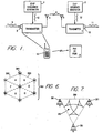
- Figure 1 shows a block diagram of a spread-spectrum communication transmitter and receiver.
- a spread-spectrum transmitter 1 comprises an input port 2 for input data 3, a chip sequence transmitter generator 4, and a transmitting antenna 5 for transmitting a spread-spectrum signal 6.
- a spread-spectrum receiver 7 comprises a receiver antenna 8, a chip sequence receiver generator 9, and an output port 10 for output data 11.
- a chip sequence 12 may be identically generated by both the transmitter generator 4 and the receiver generator 9, and appears essentially random to others not knowing the spreading code upon which it is based.
- the spread-spectrum signal 6 may have a spreading bandwidth which exceeds the bandwidth of the input data 3.
- the spread-spectrum signal 6 may also be modulated onto a communication channel having a center frequency, with the center frequency and the spreading bandwidth substantially defining a communication channel.
- the communication channel may also have a known signal dropoff for energy outside the limits of the channel.
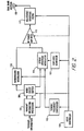
- a dual-mode transmitter in accordance with various aspects of the present invention is shown comprising an antenna 109, a mode controller 103, a mode select switch 104, transmitter-information processing means 101, a tunable-frequency synthesizer 105, a chip-code generator 107, a spread-spectrum modulator 111, a narrowband modulator 113, a power amplifier 115, and an adjustable bandpass filter 117.
- the transmitter-information means may be embodied as an information device 101.
- the information device 101 may include source encoders such as Golay encoders, error correction coding, analog-to-digital converters, etc.
- the spread-spectrum modulator 111 is coupled to the information device 101 through mode select switch 104, the tunable-frequency synthesizer 105 and the chip-code generator 107.
- the narrowband modulator 113 is coupled to the information device 101 through mode select switch 104, and the tunable-frequency synthesizer 105.
- the power amplifier 115 is coupled to the mode controller 103, the spread-spectrum modulator 111 and the narrowband modulator 113.
- the adjustable, tunable, bandpass filter 117 is coupled to the antenna 109, the power amplifier 115 and the mode controller 103.
- Narrowband or spread-spectrum modulation is selected using the mode controller 103.
- the information device 101 processes the input information signal, while the tunable-frequency synthesizer 105 generates a carrier signal, and the chip-code generator 107 generates a chip-code signal.
- the mode controller 103 controls a mode select switch 104 which directs the processed information signal to the narrowband modulator 113 or the spread-spectrum modulator 111.
- the spread-spectrum modulator 111 modulates the carrier with the processed information signal and the chip-code signal as a spread-spectrum signal, when the mode select switch 104 has been selected for spread-spectrum modulation.
- the narrowband modulator 113 modulates the carrier with the processed information signal as a narrowband modulated signal, when the mode select switch 104 is selected for narrowband modulation.
- the power amplifier 115 When the mode controller 103 is set to narrowband modulation, the power amplifier 115 amplifies the narrowband modulated signal. Where the dual modes function in distinct frequency bands, the power amplifier 115 may either be wideband enough to function in both bands, or may be adjustable to function in the band pertaining to the mode in operation, with mode controller 103 controlling its operation accordingly. When the mode controller 103 is set to spread-spectrum modulation, the power amplifier 115 amplifies the spread-spectrum signal. Similarly, with a narrowband modulation setting of the mode controller 103, the adjustable bandpass filter 117 has a bandwidth adjusted to a narrow bandwidth and corresponding frequency for passing the narrowband modulated signal. With a spread-spectrum setting of the mode controller 103, the adjustable bandpass filter 117 has a bandwidth adjusted to a wide bandwidth and corresponding frequency for passing the spread-spectrum signal.
- the present invention also includes an embodiment as a dual-mode receiver.
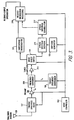
- the dual-mode receiver may comprise a mode controller 103, a tunable-frequency synthesizer 105, a chip-code generator 107, an antenna 109, an adjustable bandpass filter 117, a preamplifier 205, a frequency converter 209, an IF amplifier 211, a mode select switch 104, a spread-spectrum despreader 215, a spread-spectrum demodulator 217, a narrowband demodulator 213, and receiver-information processing means.
- the receiver-information means is embodied as a receiver-information processing device 219.
- the adjustable bandpass filter 117 is coupled to the antenna 201 and to the mode controller 103.
- the preamplifier 205 is coupled to the adjustable bandpass filter 117 and to the mode controller 103.
- the frequency converter 209 is coupled to the preamplifier 205 and the tunable-frequency synthesizer 105.
- the IF amplifier 211 is coupled to the frequency converter 209.
- the spread-spectrum despreader 215 is coupled to the chip-code generator 107 and through the mode select switch 104 to the IF amplifier 211.
- the spread-spectrum demodulator 217 is coupled to the spread-spectrum despreader 215.
- the narrowband demodulator 213 is coupled through the mode controller 103 to the IF amplifier 211.
- the mode controller 103 is used to select reception of narrowband or spread-spectrum modulation.
- the tunable-frequency synthesizer 105 generates a local oscillator signal
- the chip-code generator 107 generates a reference chip-code signal for comparison with the received chip code signal.
- the adjustable bandpass filter 117 When the mode controller 103 is set to narrowband modulation, the adjustable bandpass filter 117 is adjusted to a narrow bandwidth and corresponding frequency for passing the narrowband modulated signal. With a spread-spectrum setting of the mode controller 103, the adjustable bandpass filter 117 is adjusted to a wide bandwidth and corresponding frequency for passing the spread-spectrum signal.
- the preamplifier 205 amplifies the filtered narrowband modulated signal when the mode controller 103 is set to the narrowband modulation setting, and amplifies the filtered spread-spectrum signal when the mode controller is set to the spread-spectrum modulation setting and is switch selectable to the appropriate band for each mode where the dual mode occupy non-contiguous or widely separated frequency bands.
- the frequency converter 209 converts using the local oscillator signal, the filtered narrowband modulated signal and the filtered spread-spectrum signal to an IF signal.
- Figures 2 and 3 illustrate the implementation of a dual-band, dual-mode transmitter and receiver, respectively, for use in any narrowband application with capability to switch to a separate frequency band while employing spread spectrum modulation/demodulation in the alternate operating band.
- Fig. 2 Operation of the dual-band transmitter of Fig. 2 is as follows.
- input information may be filtered, analog-to-digital (A/D) converted if required, as determined by the mode switch control, and applied to either a narrowband or spread spectrum modulation process.
- Narrowband modulation is employed in a narrowband mode and spread spectrum modulation employed in a spread-spectrum mode. In either mode, the modulated carrier is applied to the dual-band RF power amplifier 115.
- the tunable frequency synthesizer 105 which provides the proper carrier for either conventional narrowband or spread spectrum mode, is controlled by the mode switch controller 103, outputting only one of possibly many required transmit carrier frequencies for modulation at any one time.
- the proper modulated carrier signal is applied to an adjustable, tunable bandpass filter 117 and then to the antenna 109.
- the pass band and frequency of the adjustable bandpass filter 117 is selected by the mode controller 103. This is necessary to meet transmission spurious signal level control standards.
- a single, dual-band antenna 109 then acts as a transducer to convert the electrical RF signal from the power amplifier 115 and adjustable bandpass filter 117 to an electromagnetic signal for propagation to the receiver.
- the mode controller 103 also controls the operation of a reference code generated by chip-code generator 107.
- the reference code is used as a spectrum-spreading function in the spread spectrum mode.
- the chip-code generator 107 would not operate in the conventional narrowband mode.
- This transmitter configuration is applicable to any desired dual mode system in which one mode is used in a conventional narrowband system, such is cellular telephones, while a second mode is employed for communicating with a spread spectrum system.
- Receiver operation of the receiver in Fig. 3 is as follows.
- a received signal is converted by the antenna 109 from an electromagnetic signal to an electrical signal.
- the antenna 109 may or may not be common to the transmitter.
- the received signal is then applied to an adjustable bandpass filter 117, which may or may not be common to the transmitter, and which is controller by the mode controller 103.
- the adjustable bandpass filter 203 selects the proper conventional narrowband or spread spectrum operating signal and passes it through a preamplifier 205, whose output is applied to a frequency converter 209.
- the other input to the frequency converter 209 is a local oscillator signal generated by a tunable frequency synthesizer 105 whose frequency in turn is controlled by the mode controller 103.
- the input signal is converted to an intermediate frequency (IF), which may be the same for either conventional narrowband or for spread spectrum signals.
- IF intermediate frequency
- the receiver is assumed to be the superheterodyne type, and is illustrated as a single conversion receiver, but may also be implemented by a dual or multi-conversion superheterodyne receiver without a change in the overall system's operation.
- An output signal from the frequency synthesizer 105 is multiplied with the amplified input signal from the preamplifier 205 selected by the input filter, in frequency converter 209 to produce the intermediate frequency signal.
- a tuned, fixed frequency IF amplifier 211 amplifies the received signal and applies it to a mode select switch 104 whose output is coupled to either the conventional narrowband signal demodulator 213 or the spread-spectrum signal despreader 215.
- the despreader 215 uses a reference code provided by the chip-code generator 107 to facilitate proper spread spectrum signal selection and despreading. This reference code is controlled by the mode controller 103, and may be common to the transmitter shown in Fig. 2.
- the spread-spectrum despreader 215 despreads, using the reference chip-code signal, the IF signal as a digitally modulated signal.
- the spread-spectrum demodulator 217 demodulates the digitally modulated signal as a digitally demodulated signal.
- the narrowband demodulator 213 demodulates the filtered narrowband modulated signal as a demodulated signal.
- the receiver-information device 219 processes the demodulated signal as an information signal.
- Spread spectrum signals after being despread, are demodulated by a spread-spectrum demodulator 217, separate from the narrowband demodulator 213. This is necessary because of the difference in conventional signal information modulation of the carrier is typically analog FM, while spread spectrum signals may employ digital modulation and may be digital-to-analog (D/A) converted prior to processing. If the narrowband technique used employs digital modulation, a second narrowband D/A demodulator, similar to the spread spectrum demodulator, may be employed, or the spread spectrum demodulator may be eliminated and D/A demodulation, which may be identical for both narrowband and spread spectrum modulation, may be included as a function of the received information processor.
- a second narrowband D/A demodulator similar to the spread spectrum demodulator, may be employed, or the spread spectrum demodulator may be eliminated and D/A demodulation, which may be identical for both narrowband and spread spectrum modulation, may be included as a function of the received information processor.
- spread-spectrum demodulator 217 output signals are processed, using receiver-information device 219, by filtering, digital-to-analog conversion, and amplification, as necessary, to convert it to a form that is usable to the information output destination. Processing is selected by the mode switch control 103.
- more than two modes can be supported by the same general receiver configuration of Fig. 3. This includes operation at multiple frequencies, use of multiple codes, multiple modulation formats, or time-sequential selection of operating mode.
- One embodiment of the invention includes a telephone whose first mode comprises analog voice techniques and traditional cellular frequency division multiplexed operation employing, but not limited to, narrowband radio frequency modulation techniques, such as FM, and whose second mode comprises microcellular operation including, but not limited to, digital voice commanding and/or compression techniques coupled with spread spectrum radio frequency modulation, and/or time and/or frequency division multiplexing techniques, where the cellular and microcellular modes occupy common frequency bands.
- the microcellular mode also may include a paging function, which may utilize narrowband or spread spectrum technologies, and occupy frequency bands common to the cellular and microcellular modes, or may be offset from both or either, and may be independent of the unit's telephone functionality.
- Another embodiment of the invention includes a telephone whose first mode comprises cellular frequency division multiplexed operation employing, but not limited to, narrowband radio frequency modulation techniques, such as FM, coupled with digital voice commanding and/or compression and/or time division multiplexing techniques, and whose second mode comprises microcellular operation including, but not limited to, digital voice compendium and/or compression techniques coupled with spread spectrum radio frequency modulation, and/or time and/or frequency division multiplexing techniques, where the cellular and microcellular modes occupy common or distinct frequency bands.
- the microcellular mode may also include a paging function, which may utilize narrowband or spread spectrum technologies, and may occupy frequency bands common to the cellular and microcellular modes, or may be offset from both or either, and may be independent of the unit's telephone functionality.
- a spread-spectrum signal 6 may have a spreading bandwidth which exceeds the bandwidth of the input data 3.
- the spread-spectrum signal 6 may also be modulated onto a communication channel having a center frequency, with the center frequency and the spreading bandwidth substantially defining a communication channel, and the communication channel may have a known signal dropoff for energy outside the limits of the channel. It has been found by the inventors that a particular set of selected values for the spreading bandwidth and the center frequency provide a substantial and surprising advantage when using spread-spectrum techniques for wireless communication.
- a spreading bandwidth of about 10 megahertz (MHz) or less offers several advantages in spread-spectrum wireless communication. These advantages include:
- interference avoidance is a function of both geography and frequency selection.
- microwave communication is directed over a beampath between a microwave transmitter and receiver.
- microwave stations provide critical services such as, for example, controlling the nation's electric power grid, the possibility of inadvertent disruption of such services extremely serious.
- government regulations typically require that microwave stations such as licensed OFS receivers cannot be required to tolerate more than a set level (e.g., 1 dB) of interference in their areas of operation. Users of the microwave frequency bands within the geographic area of licensed microwave stations therefore cannot operate in a zone which would cause more than 1 dB of interference to the microwave station. This zone may be referred to as an exclusion zone.
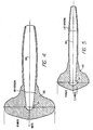
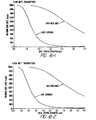
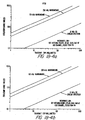
- Figures 4 and 5 show examples of exclusion zones for a specific traditional narrowband communication technique as compared to a specific type of spread spectrum communication technique.
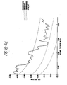
- Figure 4 compares the size of exclusion zones 331 and 332 around a microwave beampath 330 under a theoretical freespace loss model.
- the exclusion zone 332 for narrowband communication may be far larger than the exclusion zone 331 for spread spectrum communication.
- the exclusion zones 331 and 332 extend farthest in the direction of the beampath 330. With respect to other directions, the exclusion zones 331 and 332 extend relatively farther out at 90 degrees to the beampath 330, but are relatively closer, for example, in the direction opposite the beampath 330 and at various other angles as depicted in Fig. 4.
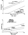
- Fig. 5 compares the size of exclusion.zones 341 and 342 around a microwave beampath 340 under a HATA loss model (median city suburban assumption).
- the present invention provides in one embodiment means for avoiding or minimizing interference with existing OFS links by selection of a particular frequency bandwidth for spread spectrum communication.
- this aspect of the present invention provides for a spread spectrum communication bandwidth that is 10 MHz or less in size.
- the present invention in one embodiment allows for selection of a 10 MHz or smaller band for spread spectrum communication so as to avoid the beampath of existing fixed microwave users or, in the worst case, to potentially interfere with only a single microwave communication user.
- the spread spectrum communication signal can interfere with at most the one known 10 MHz link.
- the spread spectrum transmitter 1 can be geographically located so as to minimize or avoid interference with that existing OFS link.
- a spread spectrum signal for communication Another way in which aspects of the present invention minimize interference with microwave communication users is by using a spread spectrum signal for communication.
- a spread-spectrum signal with its noise-like characteristics creates much less interference than a narrowband signal of comparable power.
- Approximately 83% of all OFS links use analog microwave systems which are highly susceptible to narrowband interference.
- the maximum allowable interference to a microwave receiver is commonly defined by the TSB10E standard as only a 1 dB rise in the receiver's noise threshold.
- a 10 MHz bandwidth spread spectrum signal may result in 1/100 (20 dB) less interference to an OFS receiver compared with a similar power 100 KHz bandwidth narrowband signal.
- the difference in interference is illustrated, for example, in Figs. 4 and 5.
- Figure 4 compares the exclusion zone 332 (assuming a 2 GHz microwave transmitter having a directional antenna at a height of 200 feet) of a 100 KHz narrowband signal with the exclusion zone 331 of a 10 MHz spread spectrum signal using a theoretical freespace loss model.
- the narrowband exclusion zone is 30 to 100 times larger than the spread spectrum exclusion zone.
- Figure 5 shows a similar comparison using a HATA loss model (median city suburban assumption).
- a further advantage of using a 10 MHz or smaller spread spectrum communication bandwidths is that it provides an easy migration path into the existing bands of OFS users if the OFS users can be relocated to another band.
- a spread spectrum system for communicating over a 10 MHz or smaller frequency band may be part of a cellular network.
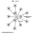
- the system may comprise a plurality of base stations 381 arranged in an approximately triangular grid 383 covering a service area, as shown in Fig. 6. Regions surrounded by three base stations 381 may comprise triangular cells 380.
- Each base station 381 may consist of six transmitters, each separately driving a 60° sector antenna.
- conformal mount, flat antennas mounted on the sides of buildings may be used in some areas where obtaining zoning for tower mounted antennas is difficult or economically undesirable.
- the frequency of each transmit sector can be different if necessary to minimize interference with existing OFS and PCS services.
- the data transmission rate may be independently set from cell to cell; that is, different sectors of a base station may transmit at different rates.
- a triangular service cell 380 is shown in Figure 7.
- Three base stations 381 having transmitters form the corners of the triangular service cell 380.
- the base stations 381 send high speed data using appropriate 60° antennas and may also use different spreading codes and/or different frequencies: Because different frequencies may be used, the described system allows for OFS frequency avoidance on a cell sector by cell sector basis.
- block interleaving and convolutional encoding may also be used to further mitigate fading and interference effects.
- An additional low rate base state/sector identifier data stream, unique to each transmitter, is employed to facilitate mobile unit location determination and data transmission query processing.
- the data on the outbound transmission in each triangular cell 380 may be different. Because each transmitter can also use a different spreading code, at a receiver 382 the signals can be separated and processed independently prior to data system combining. As shown in Fig. 7, the receiver 382 within a triangular cell 380 may be in a position to receive signals from at least three base stations 381. The receiver 382 independently despreads the three signals, performs soft decision data demodulation, and combines the data streams prior to convolutional decoding. Code based, variable delays may be introduced to synchronize data streams prior to combining.
- the base stations 381 may be synchronized using a global positioning system. By including base station position in the data stream, a user can determine his or her location to an accuracy of about 30 feet by measuring pseudorange to each of the three transmitters located at the base stations 381. The user can also obtain timing information within an accuracy of about 30 to 100 nanoseconds.
- the above described system employing triple transmission and spread spectrum communication has several important advantages.
- the system significantly reduces sensitivity to signal shadowing effects caused by buildings, hills, and similar obstacles.
- the system mitigates multipath fading effects and enhances error correction coding performance.
- a signal may be transmitted at a different frequency by one of the other two base stations 381 of the triangular cell 380.
- the system architecture reduces required transmit power and, consequently, reduces the potential for OFS interference.
- Low power transmitters e.g., as low as 100 mW
- the maximum data transmission rate is determined primarily by mutual interference considerations, while at wider separations of base stations 381, the data transmission rate is limited by noise. Even in areas near an OFS user on the same frequency, a triangular grid of transmitters 1 to 2 km apart may provide 600 kbit/s raw data rate at a bit rate error of 10 -6 .
- a compact receiver may be capable of combining multiple simultaneous 1.5 Mbit/s transmissions in a single contiguous 10 MHz band of shared spectrum. The receiver may have the option of selecting any of the available transmission frequencies based on local propagation characteristics and received S/(1+N). A user experiencing good quality reception may request a higher data rate if total traffic warrants.
- the system for transmitting spread spectrum signals over a 10 MHz bandwidth may employ time division multiplexing or duplexing in order to separate users.
- Time separation avoids interference problems, as the interference in any single time slot is simply that created by a single user.
- multiple users could share the same 10 MHz bandwidth while creating the interference of only a single continuous user.
- the aggregate interference per cell typically rises proportionally with the number of users leading to interference problems with OFS and other users sharing the electromagnetic spectrum.
- Time division multiplexing or duplexing may be combined with frequency division multiplexing or duplexing in order to increase the number of separate users.
- Another aspect of the invention relates to a technique for spread-spectrum communication which uses more than one frequency band, particularly frequency bands including the 902--928 MHz, 1850--1990 MHz, and 2.4--2.4835 GHz frequency bands.
- the spread-spectrum signal 6 may be modulated onto a communication channel.
- the communication channel may be selected from frequencies in one of a plurality of frequency bands, including the 902--928 MHz, 1850--1990 MHz, and 2.4--2.4835 GHz frequency bands, and including the 1910--1930 MHz frequency band or other future unlicensed frequency bands, or other designated frequency bands.
- a spreading bandwidth of 10 MHz may be used, or a different spreading bandwidth which may be more or less than 10 MHz.
- a different spreading bandwidth may be used from time to time; a different spreading bandwidth may be used for communication in different frequency bands, or for different uses.
- the invention provides for changing the frequency band onto which the spread-spectrum signal 6 is encoded upon a change in environment or other control trigger.
- the 902--928 MHz and 2.4--2.4835 GHz bands may be used for private access spread-spectrum communication, such as with a PBX, PABX, residential telephone, key system, Centrex system, or other related system
- the 1850--1990 MHz band may be used for public access spread-spectrum communication, such as public telephone access.
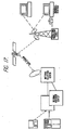
- a spread-spectrum transmitter 1 may be embodied in a handset 13 and may dynamically switch from one frequency band to another based on whether it is able to access a local PBX or PABX 14 via spread-spectrum communication.
- the handset 13 may be capable of switching between the 1850--2200 MHz band and the 2400--2485 MHz band, or between two sub-bands within those bands.
- a related system such as a residential telephone, key system, or Centrex system may be readily substituted.
- the transmitter 1 may dynamically switch from one frequency band to another based on local propagation characteristics and received S/(1+N).
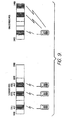
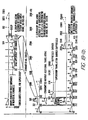
- Figure 8 shows one possible scheme for dividing the 1850--1990 MHz and 2400--2485 MHz bands into sub-bands of 10 MHz or 5MHz each.
- a first bandwidth 400 comprising frequencies from 1850--1930 MHz may be divided into sub-bands 402 of 10 MHz or 5 MHz each.
- the first bandwidth 400 is divided into sub-bands 402 of 10 MHz, then eight channels could be provided, while if divided into sub-bands 402 of 5 MHz, then sixteen channels could be provided.
- a second bandwidth 405 comprising frequencies from 2400--2480 MHz may be divided into sub-bands 406 of 10 MHz or 5 MHz each.
- a dual mode phone 410 provides access to a select one of the plurality of sub-bands 402 in the first bandwidth 400, and may be switched to provide access to a select one of the plurality of sub-bands 406 in the second bandwidth 405.
- the dual mode phone 410 While transmitting in a sub-band 402 within the first bandwidth 400, which comprises licensed frequency band to which OFS users would have access, the dual mode phone 410 may transmit using spread spectrum communication taking advantage of CDMA and/or TDMA methods in order to minimize interference with OFS microwave users. If no OFS user is present, the dual mode phone 410 may of course transmit using conventional narrowband techniques. While transmitting in a sub-band 406 within the second bandwidth 405, which comprises unlicensed frequencies available to PCS systems such as PBX, Centrex or other systems, the dual mode phone 410 may transmit using spread spectrum communication taking advantage of CDMA and/or TDMA methods in order to minimize interference with existing users, if any, or may transmit using conventional narrowband techniques. Thus, the same dual mode phone 410 may access a cellular system, for example, in a first bandwidth 400 but, by operation of a switch, may access a private access network such as a PBX or Centrex in a second bandwidth 405.
- a cellular system for example, in a
- Figure 9 shows a similar scheme for communicating in either one of two different frequency bands.
- Fig. 10 shows a dual-mode spread-spectrum modulator with two frequency bands.
- the dual-band spread-spectrum modulator uses a single, relatively narrow, synthesizer to serve two operating frequency bands.
- the synthesizer may operate in a high-side injection mode, while in the higher frequency range, the synthesizer may operate in a low-side injection mode.
- the lower frequency range may comprise about 1850 to 1990 megahertz, while the higher frequency range may comprise about 2400 to 2483.5 megahertz.
- a first frequency source 401 may generate a first frequency f1 402, while a second frequency source 403 may generate a second frequency f2 404.
- the first frequency f1 402 and the second frequency f2 404 may be coupled to a multiplier 405, which may generate a bimodal signal 406 with a frequency distribution over two.frequency ranges fL 407 and fH 408.
- the other frequency e.g., f1 may be chosen between about 300 and 440 megahertz.
- the bimodal signal 406 may be coupled to a binary encoder 409, for encoding a data stream 410.
- the data stream 410 comprising a sequence of data bits 411, may be coupled to the binary encoder 409, which may generate a first frequency, e.g., fL 407, when a data bit 411 in the data stream 410 is a "0" bit, and may generate a second frequency, e.g., fH 408, when a data bit 411 in the data stream 410 is a "1" bit.
- the present invention also provides for monitoring a frequency in each band (or transmitting to a frequency in each band) at once, because both (f1 + f2) and (f1 - f2) can be stepped down to the same intermediate frequency with a single local oscillator.
- the intermediate frequency is 260 MHz and the local oscillator is set to 2180 MHz
- the present invention allows operation at both 1920 MHz and 2440 MHz.
- the local oscillator is set 10 MHz greater
- the present invention then allows operation at both 1930 MHz and 2450 MHz, i.e., two frequencies each 10 MHz greater.
- the present invention allows reception or transmission on either frequency (or both) in the pair.
- Figure 11 shows a programmable frequency generator
- a reference frequency signal 501 may be coupled to a multiplier 502.
- the multiplier 502 may generate a signal f(s) 503, which may be coupled to a voltage-controlled oscillator (VCO) 504.
- VCO voltage-controlled oscillator
- the VCO 504 may be coupled to an output node 505, which provides an output frequency signal 506, and may also be coupled in a feedback configuration to the multiplier 502 by way of a programmable divide-by-N counter 507.
- the programmable divide-by-N counter 508 may be programmed by a set of control lines 509. In one embodiment, the divide-by-N range of the programmable divide-by-N counter 507 comprises 23 steps, from 205 to 234.
- Figure 12 is an alternative embodiment of a transmitter using a single frequency synthesizer for communicating over a plurality of frequency bands.
- an incoming data stream 601 to be modulated is provided to a spread spectrum encoder 602, which encodes the data stream 601 and outputs a'spread spectrum signal 605.
- the spread spectrum encoder 602 may encode the data stream 601 by modulating it with a PN code, or by employing an M-ary spread spectrum technique.
- the spread spectrum signal 605 is connected to a modulator 609.
- a carrier signal having a frequency f1 is generated from a signal source 603 and is also connected to modulator 609.
- Modulator 609 outputs a modulated spread spectrum signal 607.
- the modulated spread spectrum signal 607 is connected to another modulator 610.
- a frequency synthesizer 606 (e.g., such as shown in Fig. 11) generates a programmable frequency signal 608, which is also connected to the modulator 610.
- the programmable frequency signal 608 has a center frequency of fn, which may be programmed by control lines 509 such as shown, for example, in Fig. 11.
- Modulator 610 outputs a bimodal signal 611 having frequency components at frequencies f1 + fn and f1 - fn.
- the bimodal signal 611 is connected to a wideband amplifier 615.
- the wideband amplifier 615 is controlled by a band select signal 616, which causes the wideband amplifier 615 to perform at an operating point tailored for either the frequency f1 + fn or the frequency f1 - fn.
- An output of the wideband amplifier 615 is connected to two bandpass filters 619 and 620.
- One bandpass filter 619 has a center filtering frequency of f1 + fn
- the other bandpass filter 620 has a center filtering frequency of f1 - fn.
- the first bandpass filter 619 passes the portion of the amplified signal having frequency components at f1 + fn while attenuating the frequency components at f1 - fn
- the second bandpass filter 620 passes the portion of the amplified signal having frequency components at frequency f1 - fn while attenuating the frequency components at frequency f1 + fn.
- Bandpass filter 619 outputs an output signal 622 having a frequency f1 + fn
- bandpass filter 620 outputs an output signal 623 having a frequency f1 - fn.
- the Fig. 12 transmitter allows generation and transmission, using a single frequency synthesizer 606, of a signal in either or both of two frequency bands, wherein the frequency f1 + fn lies in one frequency band and the frequency f1 - fn lies in the other frequency band.
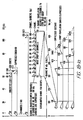
- Figure 15 is a diagram of frequency bands and sub-bands illustrating frequency pairs that may be-generated for a selected f1 and fn.
- a pair of frequency bands F H and F L are each divided into a plurality of sub-bands 750.
- the higher frequency band F H is divided into sub-bands SBH1, SBH2,...SBHN
- the lower frequency band F L is divided into sub-bands SBL1, SHL2,...SBLN.
- the sub-bands SBH1...SBHN and SBL1...SBLN are paired, with the highest of the sub-bands SBH1 in the high frequency band F H paired with the lowest of the sub-bands SBL1 in the low frequency band F L , the second highest of the sub-bands SBH2 in the high frequency band F H paired with the second lowest of the sub-bands SBL2 in the low frequency band F L , and so on, until the lowest of the sub-bands SBHN in the high frequency band F H is paired with the highest of the sub-bands SBLN in the low frequency band F L , thereby resulting in frequency pairs PAIR-1, PAIR-2,...PAIR-N.
- the high frequency band F H may comprise all or a portion of the band ranging from 1850 MHZ to 1990 MHZ, while the low frequency band F L may comprise all or a portion of the band ranging from 2.4 MHZ to 2.485 MHZ.
- the sub-bands SBH1...SBHN and SBL1...SBLN need not be contiguous within each of the main frequency bands F L and F H .
- the programmable frequency synthesizer 606 is programmed to select a frequency fn, preferably selected from one of a discrete group of N frequencies corresponding to the frequency pairs PAIR-1, PAIR-2,...PAIR-N.
- the largest selected fn allows operation over the frequency sub-band pair denoted PAIR-1, while the smallest selected fn allows operation over the frequency sub-band pair denoted PAIR-N, with the frequency selections for fn between the smallest and largest values of fn corresponding to frequency pairs PAIR-2 through PAIR-(N-1).
- the transmitter of Fig. 12 can be operated over a different pair of frequency sub-bands 750.
- Fig. 12 embodiment is described with the frequency f1 greater than frequency fn, it is also possible to have frequency fn be greater than frequency f1.
- the relative frequency difference between the higher frequency signal at a frequency fn + f1 and the lower frequency signal at a frequency fn - f1 will be a constant 2 ⁇ f1 as the frequency fn is varied according to control lines 509 or other programming means.
- Figure 13 is another embodiment of a transmitter using a single frequency synthesizer for allowing communication over a plurality of frequency bands.
- a data stream 651 is encoded by a spread spectrum encoder 652 in a similar manner to Fig. 12.
- a spread spectrum signal 655 output from the spread spectrum encoder 652 is modulated with a carrier signal 654 from a signal source 653 by modulator 659.
- the carrier signal 654 has a frequency f1.
- the modulator output 657 is connected to another modulator 660.
- a frequency synthesizer 656 (e.g., such as the one shown in Fig. 11) generates a programmable frequency signal 658, which is also connected to the modulator 660.
- the programmable frequency signal 658 has a center frequency of fn, which may be programmed by control lines 509 such as, for example, shown in Fig. 11.
- Modulator 660 outputs a bimodal signal 611 having frequency components at frequencies f1 + fn and f1 - fn.
- the bimodal signal 661 is connected to two narrowband power amplifiers 670 and 671.
- One narrowband power amplifier 670 is configured to operate at a frequency of f1 + fn, while the other narrowband power amplifier 671 is configured to operate at a frequency f1 - fn.
- Outputs from each of the narrowband power amplifiers 670 and 671 are provided to an analog multiplexer 675 (or a set of switches), which selects one of the two outputs from amplifiers 670 and 671 in response to a band select signal 676.
- the multiplexer 675 may be configured so that it selects one or both of the amplifier outputs, thereby allowing operation over a single frequency band or two frequency bands, and in either case using a single frequency synthesizer 656.
- the Fig. 13 transmitter operates over paired frequency sub-bands SBH1...SBHN and SBL1...SBLN (see Fig. 15) in a manner similar to the Fig. 12 transmitter, depending on the frequency fn selected for the programmable frequency signal 658.
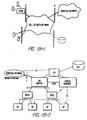
- FIG. 14 is a block diagram of a receiver for receiving and demodulating signals that may be sent over two frequency bands.
- a transmitted signal 703 is received by an antenna 700 and provided to a switch 709.
- the switch 709 connects to a first bandpass filter 714 having a center filtering frequency of f IF + fn, while in another position B, the switch 709 connects to a second bandpass filter 715 having a center filtering frequency of f IF - fn.
- frequency f IF is selected as frequency f1 used in the transmitter.
- Outputs from each of the bandpass filters 714 and 715 are connected to another switch 710.
- the switch 710 In a first position A, the switch 710 connects to the first bandpass filter 714, while in another position B, the switch 710 connects to the second bandpass filter 715.
- Switches 709 and 710 are controlled by a band select signal 719.
- the Fig. 14 receiver is configured to detect signals sent over a frequency band centered at f IF + fn
- the switches 709 and 710 are set in position B
- the receiver is configured to detect signals sent over a frequency band centered at f IF - fn. While two switches 709 and 710 are shown in Fig. 14, the same result may be achieved by using only a single switch 709 or 710. A variety of other selection means could also be utilized.
- the output from switch 710 is connected to a multiplier 720.
- a frequency synthesizer 721 generates a programmable frequency signal 722 having a frequency fn.
- the programmable frequency signal 722 is also connected to the multiplier 720.
- the frequency fn is selected to match the desired frequency sub-band pair PAIR-1, PAIR-2,... or PAIR-N, and therefore can monitor either of the two sub-bands 750 comprising the pair, depending on the setting of the band select signal.
- the Fig. 14 receiver can be adjusted to monitor two other frequency sub-bands 750.
- the sub-bands 750 that can be monitored by changing frequency fn have the same pattern as shown in Fig.
- the highest sub-band SBH1 in the high frequency band F H is paired with the lowest sub-band SBL1 in the low frequency band F L
- the lowest sub-band SBHN in the high frequency band F H is paired with the highest sub-band SBLN of the low frequency band FL.
- the Fig. 14 receiver can be modified to simultaneously monitor two frequency bands, i.e., the frequency bands centered at frequencies f IF + fn and f IF - fn.
- Multiplier 720 outputs a downconverted signal 725.
- the downconverted signal 725 is provided to an IF/demodulation block 730, which demodulates the downconverted signal 725 to recover the original information modulated thereon.
- the demodulation block 730 operates at the frequency f IF (i.e., f1), and may comprise a frequency source for generating a frequency f1, and/or a spread spectrum decoder and demodulator.
- the frequency fn in the dual-band receiver of Fig. 14 may be selected as larger than the frequency f1, in which case the bandpass filter 714 may be configured to have a center filtering frequency of fn + f IF , and bandpass filter 715 may be configured to have a center filtering frequency of fn - f IF .
- the frequency sub-bands to be monitored would be separated by a fixed 2 ⁇ f IF as the frequency fn is varied among its programmable frequency values.
- data information which is encoded for transmission
- data could comprise data, voice (encoded digitally or otherwise) error-correcting codes, control information, or other signals, and that this would be within the scope and spirit of the invention.
- Omnipoint Corporation, Oracle Data Publishing, Inc., and McCaw Cellular COmmunications, Inc. propose an innovative system that would provide a high speed, high volume information "superhighway" to address the public's needs -- the Data BroadCast Service ("DBCS").
- DBCS Data BroadCast Service
- This service would enable many important applications to be delivered at a small fraction of the cost of fiber, satellite, or landline distribution, sustainable by private funding sources, and with operations commencing within 24 months.
- DBCS is a broadcast rather than a landline system, it offers many advantages for portable applications that a national fiber optic, satellite, or wireline systems cannot.
- DBCS In order to provide these significant public benefits, DBCS relies upon advanced technology direct sequence spread spectrum devices and associated network technology. These technological advances were developed by Omnipoint, one of the DBCS principals. Since 1987, Omnipoint has been conducting laboratory research and computer modeling, and it began limited field trials in 1990 under its own experimental licenses to validate a DBCS network that would allow:
- DBCS Petitioners have designed DBCS as a comprehensive answer to information providers' data transmission and management needs.
- DBCS responds to widespread public demand for inexpensive, high speed, high volume nationwide digital data delivery.
- DBCS is an enabling technology that will permit nearly ubiquitous access to up-to-the-minute information and allow economic delivery of a rich variety of new information-based services designed to promote productivity and efficiency. The service will add a new dimension to personal computing and personal communications.
- DBCS Data Broadcast Service
- Mbit/s Megabits per second
- Petitioners represent the combined spread spectrum, data processing, and wireless communications strengths of Omnipoint, Oracle, and McCaw. Drawing from the collective resources of these industry leaders, Petitioners designed DBCS as a complete Information Age solution to information providers' needs for wide area, high speed, or high volume data delivery.
- the proposed service will allow inexpensive, ubiquitous access to a multitude of informarion sources and enable economic delivery of many needed new information-based services, including several contemplated for the proposed national fiber optic data network.
- Petitioners' efforts to pioneer this innovative new service warrant grant of a preference in the licensing of DBCS providers. 1 1 Petitioners believe that DBCS falls within the realm of services currently being considered as PCSs and that the general licensing and service rules adopted for PCSs can be appropriately modified to reflect DBCS concerns.
- Petitioners are requesting a waiver of the pioneer's preference requirement to file an associated petition for rulemaking. See Pioneer's Preference Reconsideration Order , FCC 92-57 at ⁇ 18 (rel. February 26. 1992). In the event that Petitioners' waiver request is denied, Petitioners will file a petition for rulemaking within the prescribed 30 day period.
- Petitioners are a high technology venture formed to advance a comprehensive solution for providing accessible, functional, timely data on a highly cost-effective basis.
- the venture represents the collective strengths and resources of three industry leaders. It combines Omnipoint's knowledge of spread spectrum and network design, Oracle's experience in data management, and McCaw's understanding of wireless communications. Accordingly, Petitioners hold unique qualifications to fulfill DBCS's potential for improving productivity, increasing access to information, and increasing the utility of information.
- Omnipoint is the country's leading manufacturer of true direct sequence handheld spread spectrum technology. With almost 300 man-years of experience in the design and development of spread spectrum systems, Omnipoint was the first company to develop handheld spread spectrum phones, to develop a palm sized spread spectrum modem, to test spread spectrum in microcells, to test spread spectrum phones with AIN features, to operate in conjunction with cable TV networks, to operate spread spectrum phones in the unlicensed bands, and, in late 1991, to demonstrate spread spectrum phones in the 1850-1990 MHz band. Omnipoint's advanced technology gallium arsenide integrated receiver, which allows Omnipoint's techniques to be used anywhere from 800 MHz to 2.5 GHz, is the basis of the only wireless spread spectrum network system capable of handling voice, data, and video in portable products.
- Oracle is the nation's largest provider of database software and services, and America's third largest software firm overall, with projected revenues of over one billion dollars in its current year.
- Oracle's relational database management system (“RDBMS”) is the standard for relational database products worldwide, commanding a majority of the RDBMS market.
- Oracle's RDBMS currently functions on over 80 computer platform including personal computers, workstations, minicomputers, and mainframes.
- the company's expertise in developing and managing database software that performs across a wide number of platforms brings to the venture the experience necessary to manage the extensive information that will be transmitted over the DBCS network for system managers, information providers, and information users.
- Oracle also has a large national network of sales offices and support personnel, including many technical assistance representatives, that could form an integral part of a customer support network.
- McCaw is the nation's leading provider of wireless personal communications services. McCaw and its affiliate, LIN Broadcasting Corporation, have ownership positions in over 100 cellular markets across the country with nearly 100 million potential customers, or "POPs.” The company has been at the forefront of joint cellular industry initiatives to maximize the potential of cellular radio through seamless, national wireless services. For example, McCaw has been a driving force in the formation of the Cellular One®, the North American Cellular Network, and the national Data Over Cellular project announced in April of this year. McCaw and its affiliate, LIN Broadcasting Corporation, also have extensive experience in managing mass communications cable television and broadcast television systems, as well as an extensive national telecommunications network billing and administrative infrastructure.
- DBCS is a bold response to current problems in how information is used and disseminated in today's society.
- the computer has become an indispensable technology in the information user's quest to process data efficiently, the functionality of computers for both businesses and consumers is limited by the availability of needed data and the utility of the information that is provided to the computer.
- the Petitioners By creating a data broadcast network, the Petitioners have effectively isolated the characteristics of delivery that users need so that information can be more accessible and productively used.
- DBCS involves a complete rethinking of data transmission fundamentals. Petitioners designed DBCS as a one-way data path that would be reliable enough to obviate the need for error and flow control signals, thus freeing point-to-multipoint data transfer from the constraints of expensive, circuit-based operations. By enhancing the availability and utility of information, DBCS will provide significant productivity and efficiency benefits for both businesses and consumers, as well as promoting information flow to the information disenfranchised.
- DBCS offers a complete and inexpensive solution to information age data distribution problems for a wide variety of new data services.
- the DBCS network configuration allows point-to-multipoint distribution at a very low incremental cost per information receiver.
- the high speed of the DBCS network is, in itself, a distribution solution necessary for certain time sensitive services.
- Such services include, for example, news, weather, and financial information distribution services.
- Some of these services are available today, but as text-only offerings for premium, "high-end" users, because the lack of a suitable transmission vehicle drives up delivery costs.
- DBCS could inexpensively transmit a single-spaced ASCII page in less than 3/100ths of a second and thus permit information providers to include, for example, graphical weather maps or newsworthy photographs.
- Most highly time sensitive data networks require capacity on demand even for text-only services, and thus rely on permanent networks of leased lines, satellite/FM sideband transmission, or VSAT technology. Not only are the initial fixed costs of these services prohibitive, there also are high recurring costs.
- satellite-based technologies typically rely on line of sight transmission, time sensitive data may not be available to all users.
- DBCS also offers a high volume "pipeline" -- 60 to 75 gigabytes per day using compression techniques ⁇ making feasible services relying on economic delivery of large quantities of one-way electronic data.
- Such services could include, for example, the delivery of the entire daily output of governmental information, the distribution of internal and public business documents, maintenance of specialized multimedia documentation at remote sites, the distribution of books, periodicals, and self-published manuscripts, downloading of data from databases, color graphics applications, remote publication of specialized documentation that must be regularly updated, transmission of data secured using high level encryption routines, and de-archiving from centralized electronic storage banks.
- These services are not ordinarily available because today's solution to high volume data transfer needs is circuit oriented, requiring inefficient use of two-way access lines. Since the fixed and recurring costs of these lines grows with the data rate, users must either pay high charges for circuit use or live with extremely slow throughput rates.
- the DBCS network in a very simplistic sense, can be viewed as a centralized information clearinghouse delivering data to users throughout the nation over a low cost, high speed broadcast superhighway.
- Information providers e . g ., news wire services, database services, and publishers -- forward data by various means to a central collection point. This data is rapidly collated and packaged with other sources' data, and distributed throughout the network for dissemination to end users. End users, in turn, receive the information via radio broadcasts and manipulate the information in privately beneficial ways.
- DBCS can be broken down functionally into four components: (1) information transmission to the clearinghouse; (2) distribution and control of information transmission within the network; (3) information transmission from the network to end users; and (4) end user control of transmitted information. Each of these elements is described below.
- Petitioners' have structured the DBCS network to allow information providers the greatest practical degree of flexibility. For example, virtually any electronic information source can interface with the network to provide data for broadcast. Petitioners intend to support links that include specialized gateways (e . g ., electronic mail systems or intracorporate networks); dial-up access via modem ( e . g ., incidental users); and leased data lines from information providers needing regularly scheduled broadcast time slots (e . g ., an agricultural weather service or a legal database). Information providers will be required to transmit, or maintain at the central site, a data bank containing the logical addresses of the users or groups for whom the data is targeted. Because the system is very flexible, end user billing arrangements and special data handling routines at the end user's receiver also can be structured as needed.
- gateways e . g ., electronic mail systems or intracorporate networks
- modem e . g ., incidental users
- leased data lines from information providers needing regularly scheduled broadcast time slots (e . g .
- Petitioners anticipate that DBCS local transmitters will provide wide area coverage not only in major metropolitan areas, but in all but the most remote rural regions. 5 And, using Omnipoint's unique direct sequence spread spectrum technology and the characteristics of one-way broadcast transmission ( e . g ., DBCS is a predictable interferer since there are no uncontrolled remote transmitters), these local transmitters will be capable of co-existing with the current OFS microwave users.
- DBCS receivers capable of constructive signal summing, and with the absence of capacity constraints limiting the size of DBCS cells
- Petitioners have enormous flexibility in transmitter effective radiated power ("ERP"). Thus, Petitioners arc able to use extremely high power ( e .
- DBCS is a highly efficient proposed use of spectrum. 5 Users in remote areas, however, are not precluded from accessing DBCS. Since the nationwide satellite simulcast is always available in lieu of the locally retransmitted broadcast, any user can access the DBCS network through the use of a VSAT terminal. Importantly, in those regions of the country where broadcast transmission is uneconomic; i . e ., low population density agricultural regions, VSAT use is economic and line of sight is always available. In fact, rural agricultural users are among the biggest consumers of VSATs. VSAT recipients of DBCS will still benefit from the wide variety of services available and the convenience of DBCS software.
- Intranetwork distribution and control of information Utilizing the raw data, logical addresses, and options requested by the information provider, the DBCS carrier prepares the information for transmission over the wireless network.
- the information provider's data will be addressed and the address information encrypted to ensure providers with control over access by the end user. 6
- Each provider's data are assembled into a stream relying on defined priorities for delivery; i . e ., a news source may require an extremely high priority, while a documentation update may be deferred for nighttime or another, non-busy, time for transmission.
- the data stream will then be compressed and packetized, and forward error detection codes will be added to ensure data integrity. Importantly, all of these tasks are automated and can be accomplished with negligible time lag.
- the packet stream will be uplinked to a satellite with national coverage for retransmission to the individual local transmitters that comprise Petitioners' ubiquitous broadcast network. 7 6 Information providers will also have the option of having their data encrypted. 7 Although VSAT disuibution is uneconomic for all individual end users, since Petitioners spread the transmission nerwork costs over a wide user base. VSAT discribution within the network is highly economic.
- a VSAT receives the satellite data stream and rebroadcasts the information terrestrially using a nondestructive spread spectrum technique. Due to the design of Petitioners' spread spectrum network, DBCS transmissions will penetrate interior and exterior walls to provide high quality indoor reception. Each user's receiver monitors the incoming stream from the local transmitter, becoming active only for data destined for that particular address (thus conserving battery power in portable systems). Any packets addressed to the receiver will be separated from the broadcast stream and decoded to verify error free transmission. The data will then be reassembled from the packets and passed to the DBCS Electronic LibrarianTM resident in the user's computer.
- DBCS is designed as a mass communications technology, important design goals included making DBCS receivers small and extremely low cost, while offering data rates fast enough to multiplex a wide variety of services.
- Omnipoint's spread spectrum devices and custom chip technology DBCS receivers should be small enough to fit even within handheld devices, making DBCS a viable transmission system for portable computer users as well as users at fixed locations.
- Omnipoint's technology also obviates the need for complex, costly, and power consumptive adaptive equalizers necessary to overcome delay spread induced inter-symbol interference, and thus production DBCS receivers should function in a mobile environment and cost less than $100.00. This is well within the reach of domestic computer users.
- the end user's DBCS system will include, in addition to the receiver unit, customized Electronic LibrarianTM software for the user's computer to process and store information passed to the computer by the DBCS receiver.
- the DBCS Electronic LibrarianTM generally will be a background task in the processor that will decide what actions should be performed on the data it receives. In the simplest case, the data will be stored and the user alerted to its presence. Using a DBCS application program, the user could then, among other things, preview the information, read the information once, delete the information, or republish the information locally with varying charges.
- the DBCS Electronic LibrarianTM might automatically perform an index update, modifying information in a search tree resident on the user's computer. 10
- the DBCS Electronic LibrarianTM also could pass the data through an end user-defined filter to screen for information that triggers software alarms. For example, a user could subscribe to a general news wire service and request to be notified about articles using certain key words like "telecommunications" or "PCS.”
- DBCS is not merely a conduit for information, but rather a comprehensive data management system for information providers, and a central source for the very wide variety of information services needing speed, capacity, and reliability.
- Petitioners have requested a transmission bandwidth of 10 MHz for DBCS implementation. 11 This bandwidth, which is consistent with the current OFS channelization policies, allows for robust multiple signal combining and ultimately provides for up to 1.5 Mbit/s wireless data broadcasting rates. In comparison, narrower bandwidth systems would cause significantly greater interference to an incumbent OFS user and would therefore require exclusion zones that would make DBCS impractical. For example, a 500 kHz system operating outside the OFS beam path at just 100 milliwatts would still require up to a 35 mile exclusion zone. Omnipoint's system at 100 milliwatts requires only a 5 mile exclusion zone assuming worst case free space propagation and the requirement not to raise the OFS noise floor by more than 1 dB.
- PN pseudo-noise
- Petitioners have incorporated a number of technical advances into two innovations that make DBCS possible.
- Omnipoint's development of extremely high performance direct sequence spread spectrum receivers has opened the door to creating a consumer-oriented, reliable, wide area, and high speed data broadcast network.
- Second, the combination of several advanced technologies allow DBCS to be integrated with existing spectrum licensees operating OFS microwave stations, permitting DBCS to be implemented without displacing other valuable spectrum uses. Petitioners submit that these innovations warrant a pioneer's preference.
- Petitioners' DBCS system is unlike any service implemented or proposed to date.
- DBCS provides wide area distribution of one-way data at nominal data rates of up to 1.5 Mbit/s to low cost, low power receivers -- a substantial technical achievement.
- Omnipoint's spread spectrum system provides several major pioneering innovations that enable such an extraordinarily high data rate to be delivered to low cost stationary and mobile receivers:
- DBCS point-to-multipoint radio services
- VSAT Digital Electronic Messaging Service
- no other radio based technology provides the cost and coverage characteristics of DBCS.
- DBCS provides not only "a substantial cost reduction” for consumers, but also high speed and high volume transfer capability -- an “increased ability to perform an existing work requirement.”
- DBCS is "a different use of the spectrum than previously available” within the meaning of the Pioneer's Preference Order .
- DBCS represents an enormous advance in the "speed or quality of information transfer” that "significantly reduce[s] costs to the public,' and thus should be given "careful consideration [for a pioneer's preference]." 21 21 Id .
- Petitioners After considerable laboratory investigation, computer modelling, and field testing under Omnipoint's experimental license, Petitioners already have made substantial progress in validating a DBCS system capable of coexistence with existing OFS users. The final phase of Petitioners' testing will culminate in the near future when a prototype data broadcast system is implemented in Colorado Springs, Colorado. Petitioners have a high degree of confidence that these tests will prove out DBCS technology, since, as shown in Exhibit A, extensive work already has been done to demonstrate DBCS's sharing ability.
- DBCS's ability to coexist in the current OFS band is the result of low power direct sequence spread spectrum equipment specially developed by Omnipoint to take advantage of the following characteristics of DBCS:
- DBCS has the potential to expand greatly the information service options available in the U.S. market.
- DBCS is inherently nationwide in scope and cannot viably be offered on a smaller scale.
- the fundamental concept behind DBCS is centralized collection and national distribution of information.
- full CONUS satellite delivery to individual transmitters is the only suitable intranetwork transport system.
- Creating a network of T-1 circuits to individual transmitters spaced, in places, at less than 5 miles, would be prohibitively expensive and provide lower reliability.
- DBCS's technical foundation relies on a national transmission system and DBCS providers should be issued nationwide licenses.
- DBCS is characterized economically by high initial infrastructure costs, high fixed overhead costs, and virtually nonexistent incremental costs for additional subscribers. This is true for both the broadcaster and the information provider, and has a direct impact on the Petitioners' ability to attract providers to the service. In other words, in order to recover fixed costs, Petitioners must amortize the large infrastructure and overhead costs over an extremely large customer base. Although the same theory is true to some extent for all radio services, the extreme disparity between fixed and variable costs for DBCS compels national licensing.
- DBCS end users' data needs are not categorically confined to localities or regions, but arc nationwide.
- the ability to access data from local providers in fact, generally represents market segments where the impact of DBCS will not be felt as significantly, since as the cost of distribution decreases, and the available means of distribution increases, the closer the information source gets to the end user.
- DBCS will only achieve its highest potential benefits for users if the network allows data users to access information on a nonspecific geographic basis.
- Petitioners are sensitive to the Commission's predisposition to only award national pioneer preferences where fully justified and under conditions that ensure competitive entry.
- DBCS can and should be considered a national service.
- the direct sequence spread spectrum innovations associated with DBCS will permit multiple competing licensees utilizing the same 10 MHz spectrum, if carefully coordinated, or if the Commission determines an additional 10 MHz band should be allocated to DBCS. Accordingly, Petitioners respectfully request a national pioneer preference for DBCS.
- DBCS is not simply a big business service. Since broadcasting is unmatched as a medium of mass communication, new small business, educational, and consumer users can be added at a minimal incremental cost to the DBCS provider. DBCS receivers are targeted to cost under $100.00, making DBCS a technology accessible to the majority of America. The DBCS user base can easily be extended from beyond the business world to consumers, educational users, rural users, and governmental users without additional infrastructure costs. Indeed, it is these "information poor" users that may gain the most from DBCS deployment, since serving these consumer markets can be accomplished on a highly cost-effective basis relative to these users' ability to pay. In contrast, today database subscribership is peaking, and industry analysts have concluded that such services are reaching maximal market penetration under the current data transmission infrastructure.
- Petitioners' unique DBCS network architecture in addition to providing low-cost ubiquitous coverage, allows information vendors controlled end user access. Since access to data can be regulated, the pricing of information itself can be structured to increase the availability of the information to a wider consumer base. For example, a news wire service could charge a premium for minute by minute coverage, but offer an hour by hour service to the general public and schools. Because the data has already been archived, offering the secondary service costs the information provider virtually nothing, can be provided at a nominal charge, and thus promotes increased availability of useful data for the public as a whole. Similarly, since the services provided can be user-specific, information providers could create preferential pricing policies for public institutions like libraries, schools, or government institutions. Thus, DBCS is an enabling technology that promotes data transmission for the vast portions of the population that are information disenfranchised.
- the Commission In adopting its pioneer preference policies, the Commission has sought to encourage innovation, promote efficient use of spectrum, and hasten the advent of important new wireless services to the public. In choosing "tentative selectees" for such preferences, the Commission also has focused upon the technical feasibility of bringing the concept into reality and the extent to which the requestors have committed substantial resources toward that objective. On all counts, the DBCS service and its proponents meet these strict criteria.
- DBCS will bring the exciting potential of innovative, direct sequence spread spectrum technology to the public. Spectrum efficiency would be maximized to an unprecedented level by allowing new data broadcast service providers to use a modest 10 MHz of spectrum on a shared basis with incumbent 1850-1990 MHz licensees. The resulting service would provide for the first time a digital data superhighway that spans the country and extends the capabilities of advanced computing to all segments of society.
- Petitioners' principals have already invested substantial resources and expertise in evolving the concept into reality. Work already undertaken confirms the basic feasibility of the system. Tests about to be undertaken will soon verify its full capabilities. Indeed, three major corporations with well recognized capabilities (Omnipoint, Oracle, and McCaw) have combined their technological, marketing, and economic strengths to ensure that the allocation of spectrum will be promptly followed by the deployment of a viable and important new service.
Landscapes
- Engineering & Computer Science (AREA)
- Computer Networks & Wireless Communication (AREA)
- Signal Processing (AREA)
- Quality & Reliability (AREA)
- Mobile Radio Communication Systems (AREA)
- Radio Relay Systems (AREA)
- Surface Acoustic Wave Elements And Circuit Networks Thereof (AREA)
- Transceivers (AREA)
- Transmitters (AREA)
- Input Circuits Of Receivers And Coupling Of Receivers And Audio Equipment (AREA)
Applications Claiming Priority (11)
| Application Number | Priority Date | Filing Date | Title |
|---|---|---|---|
| US08/293,671 US5887020A (en) | 1991-05-13 | 1994-08-18 | Multi-band, multi-mode spread-spectrum communication system |
| US293671 | 1994-08-18 | ||
| PCT/US1994/012464 WO1995012925A1 (fr) | 1993-11-01 | 1994-10-31 | Unite bimode sans fil a deux bandes de frequences a etalement de spectre |
| WOPCT/US94/12464 | 1994-10-31 | ||
| US485987 | 1995-06-07 | ||
| US08/485,987 US5796772A (en) | 1991-05-13 | 1995-06-07 | Multi-band, multi-mode spread-spectrum communication system |
| US08/482,292 US5694414A (en) | 1991-05-13 | 1995-06-07 | Multi-band, multi-mode spread-spectrum communication system |
| US08/483,514 US5790587A (en) | 1991-05-13 | 1995-06-07 | Multi-band, multi-mode spread-spectrum communication system |
| US482514 | 1995-06-07 | ||
| US482292 | 1995-06-07 | ||
| EP95931528A EP0776557B1 (fr) | 1994-08-18 | 1995-08-15 | Système de télécommunication a spectre étalé à bandes multiples et à modes multiples |
Related Parent Applications (2)
| Application Number | Title | Priority Date | Filing Date |
|---|---|---|---|
| EP95931528A Division EP0776557B1 (fr) | 1994-08-18 | 1995-08-15 | Système de télécommunication a spectre étalé à bandes multiples et à modes multiples |
| EP95931528.4 Division | 1996-02-29 |
Publications (2)
| Publication Number | Publication Date |
|---|---|
| EP1460772A2 true EP1460772A2 (fr) | 2004-09-22 |
| EP1460772A3 EP1460772A3 (fr) | 2004-10-13 |
Family
ID=27501601
Family Applications (2)
| Application Number | Title | Priority Date | Filing Date |
|---|---|---|---|
| EP04013982A Withdrawn EP1460772A3 (fr) | 1994-08-18 | 1995-08-15 | Système de télécommunication à spectre étalé à bandes multiples et à modes multiples |
| EP95931528A Expired - Lifetime EP0776557B1 (fr) | 1994-08-18 | 1995-08-15 | Système de télécommunication a spectre étalé à bandes multiples et à modes multiples |
Family Applications After (1)
| Application Number | Title | Priority Date | Filing Date |
|---|---|---|---|
| EP95931528A Expired - Lifetime EP0776557B1 (fr) | 1994-08-18 | 1995-08-15 | Système de télécommunication a spectre étalé à bandes multiples et à modes multiples |
Country Status (8)
| Country | Link |
|---|---|
| EP (2) | EP1460772A3 (fr) |
| JP (4) | JPH10504698A (fr) |
| KR (1) | KR970705879A (fr) |
| AT (1) | ATE326793T1 (fr) |
| CA (1) | CA2197332A1 (fr) |
| DE (1) | DE69534991T2 (fr) |
| IL (1) | IL114924A (fr) |
| WO (1) | WO1996006490A1 (fr) |
Families Citing this family (47)
| Publication number | Priority date | Publication date | Assignee | Title |
|---|---|---|---|---|
| US5901352A (en) * | 1997-02-20 | 1999-05-04 | St-Pierre; Sylvain | System for controlling multiple networks and associated services |
| WO1998055015A1 (fr) * | 1997-06-05 | 1998-12-10 | Harmen Jacob Palsma | Dispositif servant a faciliter un diagnostic medical |
| GB2335335A (en) * | 1998-03-13 | 1999-09-15 | Northern Telecom Ltd | Carrying speech-band signals over power lines |
| FI112741B (fi) | 1998-11-26 | 2003-12-31 | Nokia Corp | Menetelmä ja järjestely RF-signaalien lähettämiseksi ja vastaanottamiseksi tiedonsiirtojärjestelmien erilaisissa radiorajapinnoissa |
| KR100335631B1 (ko) * | 2000-06-14 | 2002-05-08 | 박종섭 | Imt-2000 시스템에서의 광대역/협대역 겸용 기지국송/수신 안테나 점검 장치 및 그 방법 |
| DE60009095T2 (de) | 2000-12-07 | 2004-08-19 | Motorola, Inc., Schaumburg | Mehrzweigiger Kommunikationsempfänger |
| JP4287604B2 (ja) | 2001-08-27 | 2009-07-01 | 富士通株式会社 | 移動体通信システム並びに無線基地局,無線装置及び移動端末 |
| US7440398B2 (en) | 2004-11-29 | 2008-10-21 | Honeywell International Inc. | Fault tolerant communication apparatus |
| US8326037B1 (en) | 2005-11-23 | 2012-12-04 | Matrox Electronic Systems, Ltd. | Methods and apparatus for locating an object in an image |
| JP4717668B2 (ja) | 2006-03-10 | 2011-07-06 | 株式会社エヌ・ティ・ティ・ドコモ | 送信装置及び送信方法 |
| KR100787224B1 (ko) | 2006-05-11 | 2007-12-21 | 삼성전자주식회사 | 채널 변경이 가능한 무선 통신 단말기 및 그 채널 변경방법 |
| US8856003B2 (en) | 2008-04-30 | 2014-10-07 | Motorola Solutions, Inc. | Method for dual channel monitoring on a radio device |
| US11294136B2 (en) | 2008-08-29 | 2022-04-05 | Corning Optical Communications LLC | High density and bandwidth fiber optic apparatuses and related equipment and methods |
| US8452148B2 (en) | 2008-08-29 | 2013-05-28 | Corning Cable Systems Llc | Independently translatable modules and fiber optic equipment trays in fiber optic equipment |
| US9075216B2 (en) | 2009-05-21 | 2015-07-07 | Corning Cable Systems Llc | Fiber optic housings configured to accommodate fiber optic modules/cassettes and fiber optic panels, and related components and methods |
| WO2010148336A1 (fr) | 2009-06-19 | 2010-12-23 | Corning Cable Systems Llc | Appareils à fibres optiques à large bande et à densité élevée et équipement et procédés associés |
| WO2011004525A1 (fr) | 2009-07-10 | 2011-01-13 | パナソニック株式会社 | Dispositif sans fil multibande |
| US8593828B2 (en) | 2010-02-04 | 2013-11-26 | Corning Cable Systems Llc | Communications equipment housings, assemblies, and related alignment features and methods |
| US8913866B2 (en) | 2010-03-26 | 2014-12-16 | Corning Cable Systems Llc | Movable adapter panel |
| AU2011265751B2 (en) | 2010-04-16 | 2015-09-10 | Corning Optical Communications LLC | Sealing and strain relief device for data cables |
| US9519118B2 (en) | 2010-04-30 | 2016-12-13 | Corning Optical Communications LLC | Removable fiber management sections for fiber optic housings, and related components and methods |
| US9075217B2 (en) | 2010-04-30 | 2015-07-07 | Corning Cable Systems Llc | Apparatuses and related components and methods for expanding capacity of fiber optic housings |
| US8879881B2 (en) | 2010-04-30 | 2014-11-04 | Corning Cable Systems Llc | Rotatable routing guide and assembly |
| WO2011143234A1 (fr) | 2010-05-11 | 2011-11-17 | Thomson Licensing | Procédé et appareil permettant la coexistence de systèmes ayant des largeurs de bande différentes dans un espace de télévision libre |
| US9279951B2 (en) | 2010-10-27 | 2016-03-08 | Corning Cable Systems Llc | Fiber optic module for limited space applications having a partially sealed module sub-assembly |
| US9116324B2 (en) | 2010-10-29 | 2015-08-25 | Corning Cable Systems Llc | Stacked fiber optic modules and fiber optic equipment configured to support stacked fiber optic modules |
| CA2819235C (fr) | 2010-11-30 | 2018-01-16 | Corning Cable Systems Llc | Support de corps de fibre et dispositif de reduction des tensions |
| WO2012106510A2 (fr) | 2011-02-02 | 2012-08-09 | Corning Cable Systems Llc | Ensembles de connecteurs de fibres optiques denses et connecteurs associés et câbles appropriés pour établir des connexions optiques pour des fonds de panier optiques dans des râteliers d'équipement |
| IL211663A (en) | 2011-03-10 | 2015-03-31 | Elta Systems Ltd | Device and method for dynamically distributing spectrum in satellite communications |
| US9008485B2 (en) | 2011-05-09 | 2015-04-14 | Corning Cable Systems Llc | Attachment mechanisms employed to attach a rear housing section to a fiber optic housing, and related assemblies and methods |
| WO2013003303A1 (fr) | 2011-06-30 | 2013-01-03 | Corning Cable Systems Llc | Ensembles d'équipement à fibres optiques utilisant des boîtiers hors dimensions de largeur u, et procédés associés |
| US8953924B2 (en) | 2011-09-02 | 2015-02-10 | Corning Cable Systems Llc | Removable strain relief brackets for securing fiber optic cables and/or optical fibers to fiber optic equipment, and related assemblies and methods |
| US9038832B2 (en) | 2011-11-30 | 2015-05-26 | Corning Cable Systems Llc | Adapter panel support assembly |
| US9250409B2 (en) | 2012-07-02 | 2016-02-02 | Corning Cable Systems Llc | Fiber-optic-module trays and drawers for fiber-optic equipment |
| US9042702B2 (en) | 2012-09-18 | 2015-05-26 | Corning Cable Systems Llc | Platforms and systems for fiber optic cable attachment |
| ES2551077T3 (es) | 2012-10-26 | 2015-11-16 | Ccs Technology, Inc. | Unidad de gestión de fibra óptica y dispositivo de distribución de fibra óptica |
| JP6201331B2 (ja) * | 2013-02-15 | 2017-09-27 | オムロン株式会社 | 同期シリアルインタフェース回路 |
| US8985862B2 (en) | 2013-02-28 | 2015-03-24 | Corning Cable Systems Llc | High-density multi-fiber adapter housings |
| DE102013105999A1 (de) * | 2013-06-10 | 2014-12-24 | Epcos Ag | Mobilfunkgerät mit gemeinsam genutztem Filter, Verfahren zum Betrieb des Mobilfunkgeräts und Verwendung eines Filters |
| JP6288099B2 (ja) | 2013-09-26 | 2018-03-07 | 株式会社村田製作所 | 高周波パワーアンプ、高周波フロントエンド回路、無線通信装置 |
| EP3537614A1 (fr) * | 2013-12-12 | 2019-09-11 | Huawei Technologies Co., Ltd. | Procédé et dispositif de réception de signaux à large bande, unité de traitement par radiofréquences et antenne à large bande |
| US10564248B1 (en) * | 2014-10-24 | 2020-02-18 | United States Of America As Represented By The Administrator Of National Aeronautics And Space Administration | Tunable multi-tone multi-band high-frequency synthesizer for space-borne beacon transmitter for atmospheric radio wave propagation studies |
| KR102057448B1 (ko) | 2018-12-28 | 2019-12-20 | (주)웨이버스 | 3차원 입체 격자 기반 지리정보체계 데이터 변환 시스템 |
| CN111669815B (zh) * | 2020-05-19 | 2022-07-08 | 中国联合网络通信集团有限公司 | 大气波导干扰的抑制方法及装置 |
| EP4195733A1 (fr) | 2021-12-07 | 2023-06-14 | Rohde & Schwarz GmbH & Co. KG | Dispositif de radiocommunication cognitive et son procédé de fonctionnement |
| US12289697B1 (en) | 2022-10-07 | 2025-04-29 | Rockwell Collins, Inc. | Tactical multi-rat sidelink |
| CN115685268B (zh) * | 2023-01-03 | 2023-03-31 | 成都奇芯微电子有限公司 | 基于低轨mcsk调制的数据解调判决方法 |
Citations (1)
| Publication number | Priority date | Publication date | Assignee | Title |
|---|---|---|---|---|
| US5291516A (en) | 1991-05-13 | 1994-03-01 | Omnipoint Data Company, Inc. | Dual mode transmitter and receiver |
Family Cites Families (10)
| Publication number | Priority date | Publication date | Assignee | Title |
|---|---|---|---|---|
| US4797677A (en) * | 1982-10-29 | 1989-01-10 | Istac, Incorporated | Method and apparatus for deriving pseudo range from earth-orbiting satellites |
| US5020093A (en) * | 1989-06-23 | 1991-05-28 | Motorola, Inc. | Cellular telephone operable on different cellular telephone systems |
| US5260988A (en) * | 1992-02-06 | 1993-11-09 | Motorola, Inc. | Apparatus and method for alternative radiotelephone system selection |
| JP2840496B2 (ja) * | 1992-02-26 | 1998-12-24 | 三洋電機株式会社 | デュアルバンド無線通信装置 |
| FI925472L (fi) * | 1992-12-01 | 1994-06-02 | Nokia Mobile Phones Ltd | Tiedonsiirtomenetelmä sekä -järjestelmä |
| US5299228A (en) * | 1992-12-28 | 1994-03-29 | Motorola, Inc. | Method and apparatus of reducing power consumption in a CDMA communication unit |
| US5438329A (en) * | 1993-06-04 | 1995-08-01 | M & Fc Holding Company, Inc. | Duplex bi-directional multi-mode remote instrument reading and telemetry system |
| IL111471A (en) * | 1993-11-01 | 1998-06-15 | Omnipoint Corp | A two-wheeler wireless unit with two extended spectrum frequencies |
| DE4338721A1 (de) * | 1993-11-12 | 1995-05-18 | Philips Patentverwaltung | Mehrband-Funkgerät |
| US5550895A (en) * | 1993-12-02 | 1996-08-27 | Lucent Technologies Inc. | Bimodal portable telephone |
-
1995
- 1995-08-14 IL IL11492495A patent/IL114924A/xx not_active IP Right Cessation
- 1995-08-15 WO PCT/US1995/010387 patent/WO1996006490A1/fr not_active Ceased
- 1995-08-15 CA CA002197332A patent/CA2197332A1/fr not_active Abandoned
- 1995-08-15 AT AT95931528T patent/ATE326793T1/de not_active IP Right Cessation
- 1995-08-15 EP EP04013982A patent/EP1460772A3/fr not_active Withdrawn
- 1995-08-15 JP JP8508171A patent/JPH10504698A/ja active Pending
- 1995-08-15 DE DE69534991T patent/DE69534991T2/de not_active Expired - Lifetime
- 1995-08-15 EP EP95931528A patent/EP0776557B1/fr not_active Expired - Lifetime
-
1997
- 1997-02-17 KR KR1019970701027A patent/KR970705879A/ko not_active Withdrawn
-
2004
- 2004-06-02 JP JP2004164733A patent/JP2004312766A/ja active Pending
-
2006
- 2006-10-18 JP JP2006283774A patent/JP2007116702A/ja active Pending
-
2008
- 2008-03-17 JP JP2008067712A patent/JP2008193721A/ja active Pending
Patent Citations (1)
| Publication number | Priority date | Publication date | Assignee | Title |
|---|---|---|---|---|
| US5291516A (en) | 1991-05-13 | 1994-03-01 | Omnipoint Data Company, Inc. | Dual mode transmitter and receiver |
Also Published As
| Publication number | Publication date |
|---|---|
| JP2007116702A (ja) | 2007-05-10 |
| KR970705879A (ko) | 1997-10-09 |
| DE69534991T2 (de) | 2007-05-10 |
| WO1996006490A1 (fr) | 1996-02-29 |
| EP0776557B1 (fr) | 2006-05-17 |
| JP2004312766A (ja) | 2004-11-04 |
| JP2008193721A (ja) | 2008-08-21 |
| JPH10504698A (ja) | 1998-05-06 |
| DE69534991D1 (de) | 2006-06-22 |
| EP0776557A1 (fr) | 1997-06-04 |
| CA2197332A1 (fr) | 1996-02-29 |
| IL114924A0 (en) | 1995-12-08 |
| IL114924A (en) | 2000-02-17 |
| ATE326793T1 (de) | 2006-06-15 |
| EP1460772A3 (fr) | 2004-10-13 |
| EP0776557A4 (fr) | 1998-11-25 |
Similar Documents
| Publication | Publication Date | Title |
|---|---|---|
| EP1460772A2 (fr) | Système de télécommunication à spectre étalé à bandes multiples et à modes multiples | |
| CN1146126C (zh) | 双频带收发机 | |
| US10177890B2 (en) | Spectrum allocation system and method for multi-band wireless RF data communications | |
| JP5161411B2 (ja) | 無線通信システムにおける可変出力制御の方法及び装置 | |
| EP1294211B1 (fr) | Architecture pour un réseau de communication mobile avec module de facturation des resources partagées | |
| US7962093B2 (en) | Methods and apparatuses for integration of broadcast transmission with access infrastructure of a public network for mobile communications | |
| US7986724B2 (en) | Digital audio/video broadcast on cellular systems | |
| CA2102914A1 (fr) | Emetteur et recepteur bimode | |
| AU2002251391A1 (en) | Mobile communications network, method and apparatuses | |
| EP1285511A2 (fr) | Systemes et procedes de communications radio | |
| Stavroulakis | Wireless Local Loops | |
| EP1461971B1 (fr) | Reseau d'acces pour telecommunications mobiles et procede de developpement de couverture radio | |
| Allen | Survey of Rural Information Infrastructure Technologies. | |
| Egan | Wireless Data Communications | |
| US20040133807A1 (en) | System, method and software application for secure communication | |
| Solomon | Software defined radio: a system engineering view of platform architecture and market diffusion | |
| Kenpankho | Development of broadband wireless access systems in millimeter wave band | |
| JP2002084256A (ja) | 基地局、移動局、無線データ通信システム、無線データ通信網構築方法およびコンピュータ読み取り可能な記録媒体 |
Legal Events
| Date | Code | Title | Description |
|---|---|---|---|
| PUAI | Public reference made under article 153(3) epc to a published international application that has entered the european phase |
Free format text: ORIGINAL CODE: 0009012 |
|
| PUAL | Search report despatched |
Free format text: ORIGINAL CODE: 0009013 |
|
| AC | Divisional application: reference to earlier application |
Ref document number: 0776557 Country of ref document: EP Kind code of ref document: P |
|
| AK | Designated contracting states |
Kind code of ref document: A2 Designated state(s): AT BE CH DE DK ES FR GB GR IE IT LI LU MC NL PT SE |
|
| AK | Designated contracting states |
Kind code of ref document: A3 Designated state(s): AT BE CH DE DK ES FR GB GR IE IT LI LU MC NL PT SE |
|
| 17P | Request for examination filed |
Effective date: 20050324 |
|
| AKX | Designation fees paid |
Designated state(s): AT BE CH DE DK ES FR GB GR IE IT LI LU MC NL PT SE |
|
| 17Q | First examination report despatched |
Effective date: 20091203 |
|
| STAA | Information on the status of an ep patent application or granted ep patent |
Free format text: STATUS: THE APPLICATION IS DEEMED TO BE WITHDRAWN |
|
| 18D | Application deemed to be withdrawn |
Effective date: 20110301 |