EP1461129B1 - Mit gelenken ausgestatteter fahrer für ein spielzeugfahrzeug - Google Patents
Mit gelenken ausgestatteter fahrer für ein spielzeugfahrzeug Download PDFInfo
- Publication number
- EP1461129B1 EP1461129B1 EP02802440A EP02802440A EP1461129B1 EP 1461129 B1 EP1461129 B1 EP 1461129B1 EP 02802440 A EP02802440 A EP 02802440A EP 02802440 A EP02802440 A EP 02802440A EP 1461129 B1 EP1461129 B1 EP 1461129B1
- Authority
- EP
- European Patent Office
- Prior art keywords
- toy
- handlebar
- torso
- upper leg
- hip
- Prior art date
- Legal status (The legal status is an assumption and is not a legal conclusion. Google has not performed a legal analysis and makes no representation as to the accuracy of the status listed.)
- Expired - Lifetime
Links
- 210000002414 leg Anatomy 0.000 claims abstract description 14
- 210000000629 knee joint Anatomy 0.000 claims abstract description 11
- 210000004394 hip joint Anatomy 0.000 claims abstract description 8
- 210000001624 hip Anatomy 0.000 claims description 9
- 210000003414 extremity Anatomy 0.000 claims description 2
- 238000010276 construction Methods 0.000 description 4
- 210000001503 joint Anatomy 0.000 description 2
- 230000004044 response Effects 0.000 description 2
- 230000005540 biological transmission Effects 0.000 description 1
- 230000005484 gravity Effects 0.000 description 1
- 230000008676 import Effects 0.000 description 1
- 230000003993 interaction Effects 0.000 description 1
- 230000007246 mechanism Effects 0.000 description 1
- 230000003278 mimic effect Effects 0.000 description 1
- 230000004048 modification Effects 0.000 description 1
- 238000012986 modification Methods 0.000 description 1
Images


Classifications
-
- A—HUMAN NECESSITIES
- A63—SPORTS; GAMES; AMUSEMENTS
- A63H—TOYS, e.g. TOPS, DOLLS, HOOPS OR BUILDING BLOCKS
- A63H17/00—Toy vehicles, e.g. with self-drive; ; Cranes, winches or the like; Accessories therefor
- A63H17/21—Toy vehicles, e.g. with self-drive; ; Cranes, winches or the like; Accessories therefor shaped as motorcycles with or without figures
-
- A—HUMAN NECESSITIES
- A63—SPORTS; GAMES; AMUSEMENTS
- A63H—TOYS, e.g. TOPS, DOLLS, HOOPS OR BUILDING BLOCKS
- A63H17/00—Toy vehicles, e.g. with self-drive; ; Cranes, winches or the like; Accessories therefor
- A63H17/25—Other wheeled vehicles with moving figures
-
- A—HUMAN NECESSITIES
- A63—SPORTS; GAMES; AMUSEMENTS
- A63H—TOYS, e.g. TOPS, DOLLS, HOOPS OR BUILDING BLOCKS
- A63H17/00—Toy vehicles, e.g. with self-drive; ; Cranes, winches or the like; Accessories therefor
- A63H17/22—Scooters with driver figure propelled by their wheels or by movement of the figure
Definitions
- This invention generally relates to an articulated figure used in combination with a remote-controlled toy vehicle, and more particularly to an articulated rider figure for use with a remote-controlled toy motorcycle.
- Remote-controlled vehicles are generally known. Specifically, two-wheeled remote-controlled toys are generally known.
- U.S. Patent No. 6,095,891 discloses a two-wheeled wireless controlled toy motorcycle with improved stability in which a four-bar steering mechanism and a weighted gyroscopic flywheel are used to enhance the stability of the vehicle.
- Articulated toy figures are also generally known as is their use on a toy vehicle. It would be advantageous to use an articulated rider figure in conjunction with a ridden toy vehicle like a motorcycle, particularly, to simulate the performance of freestyle tricks by the rider where the rider leaves its seat on the vehicle when the vehicle is driven over jumps and bumps.
- Patent document GB-A-2338908 discloses such a combination of toy vehicle and articulated toy figure.
- the present invention is a combination toy including a toy vehicle, with a propulsion motor for self movement and a handlebar with distal ends and an articulated toy figure with a torso and a plurality of limbs including at least a pair of arms with ends engaged with the distal ends of the handlebar while the figure is in a seated position on the toy vehicle.
- At least one spring is operably coupled with at least one of the handlebar and the arms to bias the toy figure back to the seated position on the toy vehicle when the figure is bounced up from the seated position during movement of the toy vehicle.
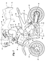
- Fig. 1 is an left elevational view of a toy in accordance with a preferred embodiment of the present invention with an articulated rider figure in a sitting position and a raised position parallel to a motorcycle portion (in phantom);
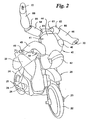
- Fig. 2 is a perspective view of the right, front side of the toy in Fig. 1 with the articulated rider figure in a raised position from the motorcycle portion;
- Fig. 3 is a front elevational view of the figure of the toy in Fig. 1;
- Fig. 4 is a left elevational view of the figure of the toy in Fig. 1;
- Fig. 5 is a front elevational view of the handlebar assembly of the toy in Fig. 1.
- the combination 10 comprises a toy vehicle portion 20 in the form of a motorcycle and an articulated rider portion 40.
- the motorcycle 20 is of conventional construction, wireless (e.g. radio) remotely controlled and comprises a main body 32, a front wheel 22 freely rotatable about a front axle 23, a back wheel 24 rotatable about a back axle 25 and operatively connected to and powered by a drive motor 34 (in phantom), and a skid plate 26 with right and left skid plate attachment points 28, 30.
- the skid plate 26 aids in keeping the vehicle 10 upright and traveling on its front and back wheels 22, 24 by allowing the vehicle 10 to lean over partially but not so far as to cause the front and back wheels 22, 24 to leave the ground.
- a motorized actuator steering movement of 36 controls the front wheel 22.
- a battery power supply 38 and a control circuit 39 with radio receiver are provided in the vehicle 20 for remotely controlled propulsion and steering.
- main body 32 of the present invention consists of a pair of mated half-shells, it is within the spirit and scope of the present invention that the main body 32 be some other monocoque construction or a separate frame/separate body construction. "Main body” is intended to cover both a monocoque construction in which the body also functions as a chassis bearing loads on the vehicle as well as a conventional chassis supporting a separately mounted body.
- the rider portion 40 is an articulated figure 41 with a handlebar assembly 50 (Fig. 5).
- the figure 41 comprises a head member 42; a torso member 44; left and right arm members 46, 48; left and right upper leg members 62, 64; left and right lower leg members 66, 68; and left and right boot attachment points 70, 72.
- the head member 42 is in engagement with the top of the torso member 44.
- the torso member 44 has a front side, a rear side, and two opposing lateral sides between the front and rear sides.
- the left and right arm members 46, 48 are rotatably engaged with the handlebar assembly 50 at their distal ends and rotatably engaged with the torso member 44 at their proximal ends, allowing hands and shoulders of the figure 41 to rotate about generally parallel horizontal, transverse axes and the figure to lift from the motorcycle portion 20 and consistently return to a seated position after the motorcycle portion 20 has landed from a jump.
- the left and right upper leg members 62, 64 are connected to the torso portion 44 with a pair of hinges, effectively acting as hip joints 61, allowing free rotation of the left and right upper leg members 62, 64 with respect to the torso member 44 about two horizontal axes.
- a first horizontal axis extends generally through the front and rear sides and the second horizontal axis extends generally through the lateral sides of the torso member 44.
- Left and right hip springs 82, 84 are connected between the torso member 44 and the left and right upper leg members 62, 64, respectively.
- the left and right lower leg members 66, 68 are attached to the left and right upper leg members 62, 64 with ball joints, providing free rotation of the left and right lower leg members 66, 68 with respect to the left and right upper leg members 62, 64.
- the ball joints effectively act as knee joints 65.
- the presence of the knee joints 65 allows for free rotation of the leg members 62, 64, 66, 68, limited only by the interaction of adjacent stop surfaces 74, 76, 78, 80 (Fig.
- the knee joints 65 are generally rotatable only about a third axis which extends generally horizontal and parallel to the second horizontal axis when the rider 40 is seated on the upright motorcycle 20.
- the hip joints 61 between the torso 44 and the upper leg members 62, 64 and the knee joints 65 between the upper leg members 62, 64 and the lower leg members 66, 68 are sufficiently lax to permit rotation, when moved by an external force, from an initial position to a displaced position and to return to the initial position upon cessation of the external force, thereby simulating possible leg movements of a human being.
- the hip springs 82, 84 act to bias the upper leg members 62, 64 toward the initial position after having been moved from the initial position.
- FIG 41 is described as having two hip springs 82, 84, it is within the spirit and scope of the present invention for only one upper leg member 62 to have one hip spring 82 and for the two legs to be connected together by a single spring proximal the hip joint of each upper leg.
- the left and right boot attachment points 70, 72 are the left and right boot attachment points 70, 72, which allow for optional engagement with the left and right skid plate attachment points 28, 30.
- the boot attachment points 70, 72 can be removably engaged (slidably or snap, depending upon the design) with the skid plate attachment points 28, 30, at the option of the user, to maintain the feet of the rider portion 40 locked to the skid plate 26 and prohibit the rider portion 40 from freely moving, thereby enabling the vehicle 10 to act as a normal remotely controlled toy motorcycle in a first mode of play.
- the attachment does not prevent all movement of the rider portion 40 on the motorcycle portion 20.
- Disengaging the boot attachment points 70, 72 from the skid plate attachment points 28, 30 allows the rider portion 40 to move freely in response to jumps and bumps which the vehicle 20 is controlled over by the user, thereby simulating free style stunts in a second mode of play.
- the handlebar assembly 50 comprises a cross member or handlebar 51; left and right grips 52, 54; a shaft 56; and left and right springs 58, 60.
- the cross member 51 is generally U-shaped, larger in width than in height, with the distal ends of the cross member 51 turned outwardly to define opposing lateral sides of the cross member 51.
- the handlebar assembly 50 is configured to generally mimic a conventional motorcycle handlebar in appearance.
- the base 51a of the cross member 51 is rigidly engaged with the motorcycle portion 20.
- the outwardly turned distal ends of the cross member 51 are hollow to accommodate the shaft 56 extending therethrough, generally parallel to the base of the cross member 51 and extending outwardly from the ends of the cross member 51.
- the left and right grips 52, 54 are engaged with the ends of the shaft 56 such that they conceal the ends of the shaft 56 protruding from the ends of the cross member 51.
- the grips 52, 54 and the shaft 56 are rotatable within the ends of the cross member 51.
- the grips 52, 54 are removably engaged by hands 49 at the distal ends of the arm members 46, 48 of the rider portion 40.
- the grips 52, 54 provide the rotatable connection of the hands 49 with the handlebar 50.
- the left and right springs 58, 60 are held within the grips 52, 54 in engagement with the shaft 56 and anchored against the ends of the cross member 51.
- the springs 58, 60 are torsional and facilitate the rider portion 40 to lift up from the motorcycle portion 20 and rotate partially about the cross member 51 in response to jumps and bumps (Figs. 1 and 2). More particularly, the torsional springs 58, 60 are under maximum torsional load when the figure 41 is seated on the motorcycle portion 20 and unload or relax as the figure 41 elevates off the motorcycle portion 20. Once the vehicle 10 completes its maneuvers, gravity overcomes the force of the torsional springs 58, 60, and the rider portion 40 falls back into a seated position on the motorcycle portion 20, reloading the torsional springs 58, 60. The springs 58, 60 are not strong enough to maintain the rider portion 40 in a rotated position. Either hand 49 can be removed from the handlebar assembly 50 to simulate one-handed stunts as the vehicle 10 is driven over bumps and jumps.
- the handlebar assembly 50 has one torsional spring 58 and one rotatable grip 52 that is engaged by the torsional spring 58 and one hand 49.
- the one hand 49 cannot be removed from the handlebar assembly 50.
- the remaining hand 49 is in optional engagement with the handlebar assembly 50 and can be removed from the handlebar assembly 50 to simulate one-handed stunts as the vehicle 10 is driven over bumps and jumps.
- the handlebar assembly 50 has no shaft 56. Instead, the grips 52, 54 are independently rotatably engaged with the handlebar assembly 50. At least one of the grips 52, 54 has at least one of the torsional springs 58, 60 engaged between the at least one grip 52, 54 and another, fixed portion of the handlebar assembly 50 so that the at least one of the grips 52, 54 is spring-biased to return the figure 41 toward the original position after having been moved.
- fixed grips 52, 54 are engaged with the handlebar assembly 50, and the figure 41 is rotatable about the grips 52, 54 at hands 86, 88.
- the torsional springs 58, 60 are engaged between the hands 86, 88 and the fixed grips 52, 54 so as to bias the figure 41 toward the original position.
- FIG. 1 In yet another embodiment not separately shown, there are separate no grips 52, 54.
- the figure 41 is rotatably engaged directly with the handlebar assembly 50, the hands 49 simply being rotatable about the outer ends of handlebar assembly 50.
- the torsional springs 58, 60 are engaged between the hands 49 of the figure 41 and the handlebar assembly 50, so as to bias the figure 41 toward the original position.
- the arms 46, 48 of the figure 41 are rotatably engaged with the handlebar assembly 50, the figure 41 not having separate distinct hands 49.
- the vehicle 20 is used with a hand operated remote control unit (not depicted) having a pair of manual controls and control and radio transmission circuitry, which is conventional.
- One manual control activates a drive motor 34, which causes rotation of the back wheel 24 about the back axle 25.
- the other manual control activates a steering actuator 35 which causes rotation of the front wheel 22.
Landscapes
- Toys (AREA)
Claims (13)
- Ein Kombinationsspielzeug (10), welches versehen ist miteinem Spielzeugfahrzeug (20) mit wenigstens einem Antriebsmotor (34) zur Eigenbewegung und einer Lenkstange (50) mit distalen Enden,einer mit Gelenken versehenen Spielzeugfigur (41) mit wenigstens einem Rumpf (44) und mehreren Gliedern einschliesslich wenigstens eines Armpaares (46, 48) mit Enden, die mit den distalen Enden der Lenkstange (50) in Eingriff sind, während die Figur (41) sich in einer sitzenden Position auf dem Fahrzeug (20) befindet, dadurch gekennzeichnet, dass es weiterhin umfasstwenigstens eine Feder (58), die wirksam mit wenigstens einem der distalen Enden der Lenkstange (50) und den Armen (46, 48) verbunden ist, um die Spielzeugfigur (41) zurück in Richtung auf die sitzende Position auf dem Fahrzeug (20) zu beaufschlagen, wenn die Figur (41) während der Bewegung des Fahrzeuges (20) aus der sitzenden Position hochschnellt.
- Kombinationsspielzeug nach Anspruch 1, bei welchem der Rumpf (44) eine Vorderseite, eine Rückseite und zwei einander gegenüberliegende laterale Seiten zwischen Vorderseite und Rückseite aufweist und die mit Gelenken versehene Figur (41) weiterhin versehen ist miteinem Paar mit Gelenken versehener Beine, die rotierbar mit dem Rumpf (44) an einem Paar Hüftgelenken (61) in Eingriff sind, wobei jedes Hüftgelenk (61) um zwei horizontale Achsen rotierbar ist, von denen eine erste horizontale Achse sich generell durch Vorder- und Rückseite und eine zweite horizontale Achse sich generell durch die lateralen Seiten des Rumpfes (44) erstreckt, und jedes Bein einen Unterschenkelteil (66, 68) und einen Oberschenkelteil (62, 64) aufweist und der Unterschenkelteil (66, 68) mit dem Oberschenkelteil (62, 64) an einem Kniegelenk (65) rotierbar in Eingriff ist und das Kniegelenk (65) um eine dritte horizontale Achse rotierbar ist, welche sich generell parallel zur zweiten horizontalen Achse erstreckt, und das Kniegelenk (65) einen Anschlag (74, 76, 78, 80) aufweist, um eine vorwärts gerichtete Uberstreckung des Unterschenkels (66, 68) in Bezug auf den Oberschenkel (62, 64) am Kniegelenk (65) zu verhindern, und Hüft- und Kniegelenke (62, 65) ausreichend locker sind, um jedem Bein eine Rotation bei Anheben aus einer Ausgangsposition zu einer höheren, verschobenen Position und die Rückkehr in die Ausgangsposition, wenn das Bein wieder frei ist, zu ermöglichen, wodurch die mit Gelenken versehene Figur (41) im wesentlichen mögliche Beinbewegungen eines Menschen simuliert, undwenigstens einer Hüftfeder (82), die zwischen wenigstens einem der Oberschenkelteile (62) und dem Rumpf (44) verbunden ist, um den wenigstens einen Oberschenkel (62) so zu beaufschlagen, dass er in die Ausgangsposition zurückkehrt, nachdem er aus der Ausgangsposition weg bewegt worden war.
- Kombinationsspielzeug nach Anspruch 1, bei welchem die Lenkstange (50) eine Anordnung darstellt, die versehen ist miteinem Lenkstangenelement (50) mit den einander gegenüberliegenden distalen Enden,einer Stange (56), die rotierbar mit dem Lenkstangenelement (50) in Eingriff ist, wobei die Stange (56) entlang einer horizontalen Achse und um diese rotierbar orientiert ist, die sich generell durch die distalen Enden des Lenkstangenelementes (50) erstreckt,einem Griff (52, 54), der mit jedem Ende der Stange (56) in Eingriff und damit rotierbar ist, Wobeidie wenigstens eine Feder (58, 60) eine Torsionsfeder ist, die wirksam zwischen dem wenigstens einen rotierbar in Eingriff befindlichen Griff (52, 54) und dem Lenkstangenelement (50) verbunden ist, um so die Stange (56) und die Griffe (52, 54) in Richtung auf eine Ausgangsposition nach Rotation der Stange (56) zu beaufschlagen.
- Ein Kombinationsspielzeug nach Anspruch 3, bei welchem die Stange (56) und die Lenkstange (50) Anschlagelemente aufweisen, um die Rotation der Stange (56) gegenüber der Lenkstangenanordnung (50) zu begrenzen.
- Ein Kombinationsspielzeug nach Anspruch 2, bei welchem die mit Gelenken versehene Spielzeugfigur (41) weiterhin versehen ist mit wenigstens einer anderen Hüftfeder (84), die zwischen einem verbleibenden Oberschenkelteil der Oberschenkelteile (64) und dem Rumpf (44) verbunden ist derart, dass das verbleibende Oberschenkelteil (84) in Richtung auf seine Ausgangsposition beaufschlagt ist, nachdem es aus der Ausgangsposition weg bewegt worden war.
- Kombinationsspielzeug nach Anspruch 2, bei welchem die wenigstens eine Hüftfeder (82) wenigstens das eine Oberschenkelteil (62) um wenigstens die zweite horizontale Achse beaufschlagt.
- Kombinationsspielzeug nach Anspruch 6, bei welchem die wenigstens eine Hüftfeder (82) wenigstens das eine Oberschenkelteil (62) um wenigstens die erste horizontale Achse beaufschlagt.
- Kombinationsspielzeug nach Anspruch 2, bei welchem die wenigstens eine Hüftfeder (82) wenigstens das eine Oberschenkelteil (62) um wenigstens die erste horizontale Achse beaufschlagt.
- Kombinationsspielzeug nach Anspruch 2, bei welchem die Unterschenkelteile (66, 68) distale Enden aufweisen, die mit dem Fahrzeug (20) entfernbar in Eingriff bringbar sind.
- Kombinationsspielzeug nach Anspruch 1, bei welchem das Fahrzeug (20) ein zweirädriges ferngesteuertes Motorrad ist.
- Kombinationsspielzeug nach Anspruch 1, bei welchem die Arme (46, 48) rotierbar mit dem Rumpf (44) in Eingriff sind.
- Kombinationsspielzeug nach Anspruch 1, bei welchem die Arme (46, 48) Armteile (46, 48) mit rotierbar angebrachten Handelementen (49) sind, die so ausgebildet sind, dass sie die distalen Enden der Lenkstangen (50) ergreifen.
- Kombinationsspielzeug nach Anspruch 12, bei welchem wenigstens eines der Handteile (49) ausgebildet ist, um eines der distalen Enden der Lenkstange (50) lösbar zu ergreifen.
Applications Claiming Priority (5)
| Application Number | Priority Date | Filing Date | Title |
|---|---|---|---|
| US33988501P | 2001-10-31 | 2001-10-31 | |
| US339885P | 2001-10-31 | ||
| US37190802P | 2002-04-11 | 2002-04-11 | |
| US371908P | 2002-04-11 | ||
| PCT/US2002/032287 WO2003037467A1 (en) | 2001-10-31 | 2002-10-10 | Articulated rider for a toy vehicle |
Publications (2)
| Publication Number | Publication Date |
|---|---|
| EP1461129A1 EP1461129A1 (de) | 2004-09-29 |
| EP1461129B1 true EP1461129B1 (de) | 2005-04-20 |
Family
ID=26991859
Family Applications (1)
| Application Number | Title | Priority Date | Filing Date |
|---|---|---|---|
| EP02802440A Expired - Lifetime EP1461129B1 (de) | 2001-10-31 | 2002-10-10 | Mit gelenken ausgestatteter fahrer für ein spielzeugfahrzeug |
Country Status (11)
| Country | Link |
|---|---|
| US (1) | US6729933B2 (de) |
| EP (1) | EP1461129B1 (de) |
| KR (1) | KR20040052253A (de) |
| CN (1) | CN1274380C (de) |
| AT (1) | ATE293484T1 (de) |
| CA (1) | CA2464103A1 (de) |
| DE (1) | DE60203823T2 (de) |
| ES (1) | ES2242099T3 (de) |
| MX (1) | MXPA04004053A (de) |
| TW (1) | TW200303228A (de) |
| WO (1) | WO2003037467A1 (de) |
Families Citing this family (15)
| Publication number | Priority date | Publication date | Assignee | Title |
|---|---|---|---|---|
| JP4024250B2 (ja) * | 2002-12-20 | 2007-12-19 | 株式会社ニッコー | 無線操縦式二輪車玩具 |
| US20050022751A1 (en) * | 2003-05-02 | 2005-02-03 | Nelson Roland D. | Interactive Animal |
| AU2003242440A1 (en) * | 2003-05-23 | 2004-12-13 | Nikko Co., Ltd. | Radio-controlled toy two-wheeled vehicle |
| JP3102994U (ja) * | 2004-01-26 | 2004-07-22 | 株式会社トミー | 二輪走行玩具 |
| US7503828B2 (en) * | 2004-10-26 | 2009-03-17 | Mattel, Inc. | Remote-controlled motorcycle and method of counter-steering |
| USD559332S1 (en) | 2005-01-07 | 2008-01-08 | Mattel, Inc. | Toy motorcycle |
| US7624835B2 (en) | 2006-03-31 | 2009-12-01 | Honda Motor Company, Ltd. | Protective cover for the underside of a vehicle |
| US7654881B2 (en) | 2006-06-12 | 2010-02-02 | Mattel, Inc. | Action figure with movable appendages |
| GB0611690D0 (en) * | 2006-06-14 | 2006-07-26 | Carterbench Product Dev Ltd | Toy vehicle |
| DE212008000063U1 (de) | 2007-10-03 | 2010-07-01 | Mattel, Inc. (n.d.Ges.d. Staates Delaware), El Segundo | Miniaturspielzeug für das Halten einer Puppe auf einem Fahrrad |
| US7985117B2 (en) * | 2007-10-03 | 2011-07-26 | Mattel, Inc. | Toy vehicle for supporting a doll on a vehicle |
| US7942719B2 (en) | 2007-10-03 | 2011-05-17 | Mattel, Inc. | Miniature toy for supporting doll on a bicycle |
| US8162715B2 (en) | 2008-04-16 | 2012-04-24 | Mattel, Inc. | Remote-controlled toy vehicle |
| US8306512B2 (en) | 2009-07-09 | 2012-11-06 | Cubic Corporation | Transit account management with text messaging |
| GB2487217A (en) * | 2011-01-13 | 2012-07-18 | Hasbro Inc | Toy power source |
Family Cites Families (26)
| Publication number | Priority date | Publication date | Assignee | Title |
|---|---|---|---|---|
| US1692714A (en) | 1926-11-12 | 1928-11-20 | Clare A Wetzell | Projecting figure wheel toy |
| GB479430A (en) * | 1936-07-29 | 1938-01-31 | Hubert Charles Henry Townend | Improvements in or relating to means for the balancing and controlling of toy bicycles |
| US2175845A (en) | 1939-01-21 | 1939-10-10 | Marx & Co Louis | Vehicle and figure toy |
| US2250215A (en) | 1940-10-25 | 1941-07-22 | Unique Art Mfg Co Inc | Aerial effect toy |
| DE836156C (de) * | 1950-01-30 | 1952-04-10 | Hans Mangold | Laufwerkbetriebenes Spielfahrzeug |
| US2814908A (en) | 1955-06-21 | 1957-12-03 | Ernst Max | Toy motor cycle with mounting and dismounting cyclist |
| US3546814A (en) | 1969-02-24 | 1970-12-15 | Federico Melendez | Robot driver of a two-wheel motorcycle |
| US3650067A (en) | 1969-11-24 | 1972-03-21 | G L J Toy Co Inc | Gyroscope toy |
| US3886682A (en) | 1974-02-01 | 1975-06-03 | Ideal Toy Corp | Toy vehicle and launcher |
| JPS55156799U (de) * | 1979-04-27 | 1980-11-11 | ||
| JPS5613971A (en) | 1979-07-13 | 1981-02-10 | Kuniaki Miyazawa | Model twoowheeled automobile which is capable of remoteecontrol |
| US4267663A (en) | 1979-10-25 | 1981-05-19 | Sin Nagahara | Radio-controlled steering device for toy motorcycles |
| US4290228A (en) | 1980-02-13 | 1981-09-22 | Adolph E. Goldfarb | Toy vehicles with automatic banking |
| US4342175A (en) | 1980-07-21 | 1982-08-03 | Entex Industries, Inc. | Radio controlled motorcycle |
| US4355482A (en) * | 1980-11-26 | 1982-10-26 | Mattel, Inc. | Skating doll |
| US4363186A (en) | 1981-02-12 | 1982-12-14 | Adolph E. Goldfarb | Toy motorcycle and launcher |
| US4526554A (en) | 1981-02-12 | 1985-07-02 | Adolph E. Goldfarb | Toy motorcycle and launcher apparatus |
| JPS6041280Y2 (ja) * | 1982-09-25 | 1985-12-14 | 新正工業株式会社 | オ−トバイ玩具 |
| US4563164A (en) | 1984-03-21 | 1986-01-07 | Asahi Corporation | Two wheeled toy vehicle |
| JPH0649346Y2 (ja) | 1989-02-01 | 1994-12-14 | 株式会社グリーン | 無線操縦式二輪車玩具 |
| US5069649A (en) * | 1990-11-19 | 1991-12-03 | Wu Hai M | Toy police car with a retractable helicopter |
| US5368516A (en) | 1993-10-21 | 1994-11-29 | Bang Zoom Design Inc. | Radio controlled two-wheeled toy motorcycle |
| US6074271A (en) | 1997-08-26 | 2000-06-13 | Derrah; Steven | Radio controlled skateboard with robot |
| GB9813952D0 (en) * | 1998-06-30 | 1998-08-26 | Bromham Christopher | Track racing game |
| US6095891A (en) | 1998-11-18 | 2000-08-01 | Bang Zoom Design, Ltd. | Remote control toy vehicle with improved stability |
| US6095892A (en) | 1998-12-17 | 2000-08-01 | Moe; Courtney A. | Motorcycle race track with moving rider figurines |
-
2002
- 2002-10-10 US US10/268,508 patent/US6729933B2/en not_active Expired - Fee Related
- 2002-10-10 EP EP02802440A patent/EP1461129B1/de not_active Expired - Lifetime
- 2002-10-10 ES ES02802440T patent/ES2242099T3/es not_active Expired - Lifetime
- 2002-10-10 AT AT02802440T patent/ATE293484T1/de not_active IP Right Cessation
- 2002-10-10 WO PCT/US2002/032287 patent/WO2003037467A1/en not_active Ceased
- 2002-10-10 KR KR10-2004-7006116A patent/KR20040052253A/ko not_active Withdrawn
- 2002-10-10 CA CA002464103A patent/CA2464103A1/en not_active Abandoned
- 2002-10-10 CN CNB028215141A patent/CN1274380C/zh not_active Expired - Fee Related
- 2002-10-10 MX MXPA04004053A patent/MXPA04004053A/es unknown
- 2002-10-10 DE DE60203823T patent/DE60203823T2/de not_active Expired - Lifetime
- 2002-10-31 TW TW091132329A patent/TW200303228A/zh unknown
Also Published As
| Publication number | Publication date |
|---|---|
| ES2242099T3 (es) | 2005-11-01 |
| KR20040052253A (ko) | 2004-06-22 |
| DE60203823T2 (de) | 2006-01-26 |
| CA2464103A1 (en) | 2003-05-08 |
| CN1274380C (zh) | 2006-09-13 |
| CN1578694A (zh) | 2005-02-09 |
| MXPA04004053A (es) | 2004-09-06 |
| DE60203823D1 (de) | 2005-05-25 |
| US6729933B2 (en) | 2004-05-04 |
| WO2003037467A1 (en) | 2003-05-08 |
| US20030082989A1 (en) | 2003-05-01 |
| HK1070012A1 (en) | 2005-06-10 |
| TW200303228A (en) | 2003-09-01 |
| EP1461129A1 (de) | 2004-09-29 |
| ATE293484T1 (de) | 2005-05-15 |
Similar Documents
| Publication | Publication Date | Title |
|---|---|---|
| US6729933B2 (en) | Articulated rider for a toy vehicle | |
| EP1251916B1 (de) | Fernbedientes skateboard mit einer auf bewegung reagierenden puppe | |
| US6074271A (en) | Radio controlled skateboard with robot | |
| US6682394B2 (en) | Radio controlled two wheeled vehicle | |
| US5328193A (en) | Scooting and coasting golf cart tricycle | |
| US7503828B2 (en) | Remote-controlled motorcycle and method of counter-steering | |
| US7226062B1 (en) | Recreational wheelie vehicle | |
| US7837209B2 (en) | Tri-axial control device | |
| US4824415A (en) | Doll with remote controlled supporting accessory | |
| CN102167113A (zh) | 可摇摆电动童车 | |
| US7291053B2 (en) | Radio-controlled toy two-wheeled vehicle | |
| US6616501B2 (en) | Trim adjustment feature for toy vehicles | |
| US20020086609A1 (en) | Toy action figures with manipulating stem and selectably articulatable joints | |
| CN201254251Y (zh) | 重心自转型滑板车 | |
| US20060278455A1 (en) | Modular ride-on vehicle | |
| US20070096410A1 (en) | Tri Control Platform Device | |
| CN221316519U (zh) | 一种多功能玩具车 | |
| HK1070012B (en) | Articulated rider for a toy vehicle | |
| JP3103657U (ja) | キックボード | |
| US20160362157A1 (en) | Body motion powered ride-on vehicle | |
| HK1124006B (en) | Remote-controlled motorcycle and method of counter-steering | |
| CN102285409A (zh) | 一种脚踏童车 |
Legal Events
| Date | Code | Title | Description |
|---|---|---|---|
| PUAI | Public reference made under article 153(3) epc to a published international application that has entered the european phase |
Free format text: ORIGINAL CODE: 0009012 |
|
| GRAP | Despatch of communication of intention to grant a patent |
Free format text: ORIGINAL CODE: EPIDOSNIGR1 |
|
| 17P | Request for examination filed |
Effective date: 20040429 |
|
| AK | Designated contracting states |
Kind code of ref document: A1 Designated state(s): AT BE BG CH CY CZ DE DK EE ES FI FR GB GR IE IT LI LU MC NL PT SE SK TR |
|
| AX | Request for extension of the european patent |
Extension state: AL LT LV MK RO SI |
|
| GRAS | Grant fee paid |
Free format text: ORIGINAL CODE: EPIDOSNIGR3 |
|
| GRAA | (expected) grant |
Free format text: ORIGINAL CODE: 0009210 |
|
| AK | Designated contracting states |
Kind code of ref document: B1 Designated state(s): AT BE BG CH CY CZ DE DK EE ES FI FR GB GR IE IT LI LU MC NL PT SE SK TR |
|
| PG25 | Lapsed in a contracting state [announced via postgrant information from national office to epo] |
Ref country code: TR Free format text: LAPSE BECAUSE OF FAILURE TO SUBMIT A TRANSLATION OF THE DESCRIPTION OR TO PAY THE FEE WITHIN THE PRESCRIBED TIME-LIMIT Effective date: 20050420 Ref country code: SK Free format text: LAPSE BECAUSE OF FAILURE TO SUBMIT A TRANSLATION OF THE DESCRIPTION OR TO PAY THE FEE WITHIN THE PRESCRIBED TIME-LIMIT Effective date: 20050420 Ref country code: AT Free format text: LAPSE BECAUSE OF FAILURE TO SUBMIT A TRANSLATION OF THE DESCRIPTION OR TO PAY THE FEE WITHIN THE PRESCRIBED TIME-LIMIT Effective date: 20050420 Ref country code: BE Free format text: LAPSE BECAUSE OF FAILURE TO SUBMIT A TRANSLATION OF THE DESCRIPTION OR TO PAY THE FEE WITHIN THE PRESCRIBED TIME-LIMIT Effective date: 20050420 Ref country code: EE Free format text: LAPSE BECAUSE OF FAILURE TO SUBMIT A TRANSLATION OF THE DESCRIPTION OR TO PAY THE FEE WITHIN THE PRESCRIBED TIME-LIMIT Effective date: 20050420 Ref country code: CH Free format text: LAPSE BECAUSE OF FAILURE TO SUBMIT A TRANSLATION OF THE DESCRIPTION OR TO PAY THE FEE WITHIN THE PRESCRIBED TIME-LIMIT Effective date: 20050420 Ref country code: LI Free format text: LAPSE BECAUSE OF FAILURE TO SUBMIT A TRANSLATION OF THE DESCRIPTION OR TO PAY THE FEE WITHIN THE PRESCRIBED TIME-LIMIT Effective date: 20050420 Ref country code: NL Free format text: LAPSE BECAUSE OF FAILURE TO SUBMIT A TRANSLATION OF THE DESCRIPTION OR TO PAY THE FEE WITHIN THE PRESCRIBED TIME-LIMIT Effective date: 20050420 Ref country code: FI Free format text: LAPSE BECAUSE OF FAILURE TO SUBMIT A TRANSLATION OF THE DESCRIPTION OR TO PAY THE FEE WITHIN THE PRESCRIBED TIME-LIMIT Effective date: 20050420 Ref country code: CZ Free format text: LAPSE BECAUSE OF FAILURE TO SUBMIT A TRANSLATION OF THE DESCRIPTION OR TO PAY THE FEE WITHIN THE PRESCRIBED TIME-LIMIT Effective date: 20050420 |
|
| REG | Reference to a national code |
Ref country code: GB Ref legal event code: FG4D |
|
| REG | Reference to a national code |
Ref country code: CH Ref legal event code: EP |
|
| REG | Reference to a national code |
Ref country code: IE Ref legal event code: FG4D |
|
| REF | Corresponds to: |
Ref document number: 60203823 Country of ref document: DE Date of ref document: 20050525 Kind code of ref document: P |
|
| PG25 | Lapsed in a contracting state [announced via postgrant information from national office to epo] |
Ref country code: GR Free format text: LAPSE BECAUSE OF FAILURE TO SUBMIT A TRANSLATION OF THE DESCRIPTION OR TO PAY THE FEE WITHIN THE PRESCRIBED TIME-LIMIT Effective date: 20050720 Ref country code: SE Free format text: LAPSE BECAUSE OF FAILURE TO SUBMIT A TRANSLATION OF THE DESCRIPTION OR TO PAY THE FEE WITHIN THE PRESCRIBED TIME-LIMIT Effective date: 20050720 Ref country code: DK Free format text: LAPSE BECAUSE OF FAILURE TO SUBMIT A TRANSLATION OF THE DESCRIPTION OR TO PAY THE FEE WITHIN THE PRESCRIBED TIME-LIMIT Effective date: 20050720 Ref country code: BG Free format text: LAPSE BECAUSE OF FAILURE TO SUBMIT A TRANSLATION OF THE DESCRIPTION OR TO PAY THE FEE WITHIN THE PRESCRIBED TIME-LIMIT Effective date: 20050720 |
|
| PG25 | Lapsed in a contracting state [announced via postgrant information from national office to epo] |
Ref country code: PT Free format text: LAPSE BECAUSE OF FAILURE TO SUBMIT A TRANSLATION OF THE DESCRIPTION OR TO PAY THE FEE WITHIN THE PRESCRIBED TIME-LIMIT Effective date: 20050920 |
|
| PG25 | Lapsed in a contracting state [announced via postgrant information from national office to epo] |
Ref country code: IE Free format text: LAPSE BECAUSE OF NON-PAYMENT OF DUE FEES Effective date: 20051010 Ref country code: CY Free format text: LAPSE BECAUSE OF FAILURE TO SUBMIT A TRANSLATION OF THE DESCRIPTION OR TO PAY THE FEE WITHIN THE PRESCRIBED TIME-LIMIT Effective date: 20051010 |
|
| PG25 | Lapsed in a contracting state [announced via postgrant information from national office to epo] |
Ref country code: MC Free format text: LAPSE BECAUSE OF NON-PAYMENT OF DUE FEES Effective date: 20051031 Ref country code: LU Free format text: LAPSE BECAUSE OF NON-PAYMENT OF DUE FEES Effective date: 20051031 |
|
| REG | Reference to a national code |
Ref country code: CH Ref legal event code: PL |
|
| NLV1 | Nl: lapsed or annulled due to failure to fulfill the requirements of art. 29p and 29m of the patents act | ||
| REG | Reference to a national code |
Ref country code: ES Ref legal event code: FG2A Ref document number: 2242099 Country of ref document: ES Kind code of ref document: T3 |
|
| PLBE | No opposition filed within time limit |
Free format text: ORIGINAL CODE: 0009261 |
|
| STAA | Information on the status of an ep patent application or granted ep patent |
Free format text: STATUS: NO OPPOSITION FILED WITHIN TIME LIMIT |
|
| ET | Fr: translation filed | ||
| 26N | No opposition filed |
Effective date: 20060123 |
|
| REG | Reference to a national code |
Ref country code: IE Ref legal event code: MM4A |
|
| PGFP | Annual fee paid to national office [announced via postgrant information from national office to epo] |
Ref country code: DE Payment date: 20091028 Year of fee payment: 8 Ref country code: ES Payment date: 20091026 Year of fee payment: 8 |
|
| PGFP | Annual fee paid to national office [announced via postgrant information from national office to epo] |
Ref country code: FR Payment date: 20091029 Year of fee payment: 8 Ref country code: GB Payment date: 20091026 Year of fee payment: 8 Ref country code: IT Payment date: 20091026 Year of fee payment: 8 |
|
| GBPC | Gb: european patent ceased through non-payment of renewal fee |
Effective date: 20101010 |
|
| PG25 | Lapsed in a contracting state [announced via postgrant information from national office to epo] |
Ref country code: FR Free format text: LAPSE BECAUSE OF NON-PAYMENT OF DUE FEES Effective date: 20101102 |
|
| REG | Reference to a national code |
Ref country code: FR Ref legal event code: ST Effective date: 20110630 |
|
| PG25 | Lapsed in a contracting state [announced via postgrant information from national office to epo] |
Ref country code: GB Free format text: LAPSE BECAUSE OF NON-PAYMENT OF DUE FEES Effective date: 20101010 |
|
| REG | Reference to a national code |
Ref country code: DE Ref legal event code: R119 Ref document number: 60203823 Country of ref document: DE Effective date: 20110502 |
|
| REG | Reference to a national code |
Ref country code: ES Ref legal event code: FD2A Effective date: 20111118 |
|
| PG25 | Lapsed in a contracting state [announced via postgrant information from national office to epo] |
Ref country code: IT Free format text: LAPSE BECAUSE OF NON-PAYMENT OF DUE FEES Effective date: 20101010 |
|
| PG25 | Lapsed in a contracting state [announced via postgrant information from national office to epo] |
Ref country code: ES Free format text: LAPSE BECAUSE OF NON-PAYMENT OF DUE FEES Effective date: 20101011 |
|
| PG25 | Lapsed in a contracting state [announced via postgrant information from national office to epo] |
Ref country code: DE Free format text: LAPSE BECAUSE OF NON-PAYMENT OF DUE FEES Effective date: 20110502 |