EP1462144A1 - Hydrocephalus-Ableitvorrichtung mit Endoskop-Plazierungsmöglichkeit - Google Patents
Hydrocephalus-Ableitvorrichtung mit Endoskop-Plazierungsmöglichkeit Download PDFInfo
- Publication number
- EP1462144A1 EP1462144A1 EP04251799A EP04251799A EP1462144A1 EP 1462144 A1 EP1462144 A1 EP 1462144A1 EP 04251799 A EP04251799 A EP 04251799A EP 04251799 A EP04251799 A EP 04251799A EP 1462144 A1 EP1462144 A1 EP 1462144A1
- Authority
- EP
- European Patent Office
- Prior art keywords
- catheter
- inflow catheter
- connector
- fluid
- retaining ring
- Prior art date
- Legal status (The legal status is an assumption and is not a legal conclusion. Google has not performed a legal analysis and makes no representation as to the accuracy of the status listed.)
- Granted
Links
- 208000003906 hydrocephalus Diseases 0.000 title description 5
- 239000012530 fluid Substances 0.000 claims abstract description 56
- 230000007246 mechanism Effects 0.000 claims abstract description 39
- 230000002093 peripheral effect Effects 0.000 claims description 9
- 238000004891 communication Methods 0.000 claims description 5
- 229920001296 polysiloxane Polymers 0.000 claims description 4
- 230000001105 regulatory effect Effects 0.000 claims description 4
- 238000000034 method Methods 0.000 abstract description 8
- 239000000853 adhesive Substances 0.000 abstract description 4
- 230000001070 adhesive effect Effects 0.000 abstract description 4
- 230000008569 process Effects 0.000 abstract description 4
- 238000002324 minimally invasive surgery Methods 0.000 abstract description 3
- 230000002861 ventricular Effects 0.000 description 15
- 210000001175 cerebrospinal fluid Anatomy 0.000 description 9
- 238000005086 pumping Methods 0.000 description 8
- 230000037361 pathway Effects 0.000 description 7
- 238000002513 implantation Methods 0.000 description 4
- 238000002347 injection Methods 0.000 description 4
- 239000007924 injection Substances 0.000 description 4
- 210000004556 brain Anatomy 0.000 description 3
- 239000000463 material Substances 0.000 description 3
- 238000001356 surgical procedure Methods 0.000 description 3
- 238000012800 visualization Methods 0.000 description 3
- 239000004677 Nylon Substances 0.000 description 2
- 230000000151 anti-reflux effect Effects 0.000 description 2
- 230000008901 benefit Effects 0.000 description 2
- 230000006835 compression Effects 0.000 description 2
- 238000007906 compression Methods 0.000 description 2
- 238000002591 computed tomography Methods 0.000 description 2
- 230000001276 controlling effect Effects 0.000 description 2
- 238000011010 flushing procedure Methods 0.000 description 2
- 238000003384 imaging method Methods 0.000 description 2
- 230000004048 modification Effects 0.000 description 2
- 238000012986 modification Methods 0.000 description 2
- 229920001778 nylon Polymers 0.000 description 2
- 238000005192 partition Methods 0.000 description 2
- 210000004761 scalp Anatomy 0.000 description 2
- 238000004513 sizing Methods 0.000 description 2
- 210000003625 skull Anatomy 0.000 description 2
- 208000002667 Subdural Hematoma Diseases 0.000 description 1
- 229910001069 Ti alloy Inorganic materials 0.000 description 1
- RTAQQCXQSZGOHL-UHFFFAOYSA-N Titanium Chemical compound [Ti] RTAQQCXQSZGOHL-UHFFFAOYSA-N 0.000 description 1
- 210000001015 abdomen Anatomy 0.000 description 1
- 230000009471 action Effects 0.000 description 1
- 239000000560 biocompatible material Substances 0.000 description 1
- 230000017531 blood circulation Effects 0.000 description 1
- 210000001124 body fluid Anatomy 0.000 description 1
- 210000005013 brain tissue Anatomy 0.000 description 1
- 210000004289 cerebral ventricle Anatomy 0.000 description 1
- 230000000694 effects Effects 0.000 description 1
- 238000002674 endoscopic surgery Methods 0.000 description 1
- 230000002706 hydrostatic effect Effects 0.000 description 1
- 230000001771 impaired effect Effects 0.000 description 1
- 238000007917 intracranial administration Methods 0.000 description 1
- 229920002529 medical grade silicone Polymers 0.000 description 1
- 239000000203 mixture Substances 0.000 description 1
- 230000004962 physiological condition Effects 0.000 description 1
- 230000000284 resting effect Effects 0.000 description 1
- 238000000926 separation method Methods 0.000 description 1
- 238000011477 surgical intervention Methods 0.000 description 1
- 230000008685 targeting Effects 0.000 description 1
- 229910052719 titanium Inorganic materials 0.000 description 1
- 239000010936 titanium Substances 0.000 description 1
- 238000012546 transfer Methods 0.000 description 1
- 230000002792 vascular Effects 0.000 description 1
Images




Classifications
-
- A—HUMAN NECESSITIES
- A61—MEDICAL OR VETERINARY SCIENCE; HYGIENE
- A61M—DEVICES FOR INTRODUCING MEDIA INTO, OR ONTO, THE BODY; DEVICES FOR TRANSDUCING BODY MEDIA OR FOR TAKING MEDIA FROM THE BODY; DEVICES FOR PRODUCING OR ENDING SLEEP OR STUPOR
- A61M27/00—Drainage appliance for wounds or the like, i.e. wound drains, implanted drains
- A61M27/002—Implant devices for drainage of body fluids from one part of the body to another
- A61M27/006—Cerebrospinal drainage; Accessories therefor, e.g. valves
Definitions
- the present invention relates to medical devices for directing bodily fluids from one region of a patient to another region. More specifically, this invention relates to a shunt system having endoscopic placement features that allow its minimally invasive placement within a patient, and apparatus to facilitate such endoscopic placement.
- Hydrocephalus is a condition afflicting patients who are unable to regulate cerebrospinal fluid flow through their body's own natural pathways.
- cerebrospinal fluid is normally absorbed by the body's venous system.
- the cerebrospinal fluid is not absorbed in this manner, but instead accumulates in the ventricles of the patient's brain. If left untreated, the increasing volume of fluid elevates the patient's intracranial pressure and can lead to serious medical conditions such as subdural hematoma, compression of the brain tissue, and impaired blood flow.
- the treatment of hydrocephalus has conventionally involved draining the excess fluid away from the ventricles and rerouting the cerebrospinal fluid to another area of the patient's body, such as the abdomen or vascular system.
- a drainage system commonly referred to as a shunt, is often used to carry out the transfer of fluid.
- a shunt In order to install the shunt, typically a scalp incision is made and a small hole is drilled in the skull.
- the proximal end of the shunt which usually includes a proximal, or ventricular, catheter, is installed in the ventricular cavity of the patient's brain.
- the distal end of the shunt which includes a distal, or drainage, catheter, is installed in that portion of the patient's body where the excess fluid is to be reintroduced.
- a pump or valve can be placed between the proximal and distal catheters. If the pump or valve is not equipped with anti-siphon features and such features are desirable, a siphon control device can be separately included. The siphon control device can be positioned within the fluidic pathway, usually between the shunt valve and the drainage catheter.
- the siphon control device avoids overdrainage caused by the siphoning effect of hydrostatic pressure in the distal shunt catheter, which can be created by the elevation of the proximal catheter inlet with respect to the distal catheter outlet, i.e., when the patient sits or stands.
- proximal and distal catheters i.e., proximal and distal catheters, shunt valve, anti-siphon device, tubing, etc.
- proximal catheters i.e., proximal and distal catheters, shunt valve, anti-siphon device, tubing, etc.
- the proximal catheter is inserted directly into the ventricle cavity, after which the shunt valve and a pre-attached distal catheter are then implanted near the surface of the skull at an approximately 90° angle with respect to the proximal catheter.
- the proximal catheter is then attached by means of suturing surgical tubing to an inlet port on the shunt valve, thereby forming a right angle with respect to the shunt valve.
- the present invention provides a shunt system for controlling the flow of fluid from one region of a patient to a different region of the patient's body.
- the shunt system includes endoscopic placement features so that the system can be placed endoscopically for implantation in a minimally invasive surgery.
- a single, fluid flow control device having flow control characteristics previously obtainable only by connecting in series two or more shunt system components.
- the shunt system can be assembled quickly and easily, without the need for suturing. The present assembly process minimizes the possibility of any unintended fluid leakage from the device, and preferably requires no adhesive to secure any of the components forming the shunt system to one another.
- the shunt system comprises a shunt device contained within a housing.
- the shunt device is comprised of a valve mechanism for regulating fluid flow into and out of the shunt system, a pump chamber in fluid communication with the valve mechanism, and a reservoir which is also connected to and in fluid communication with the pump chamber.
- the reservoir includes a top section and a base section that terminates in a catheter connector. At least a portion of the connector extends out of the housing, and in one exemplary embodiment both the base section including the connector extends out of the housing.
- the shunt system also includes an inflow catheter and an outflow catheter, each catheter having first and second ends, and a channel extending between the first and second ends for carrying fluid within the catheter.
- each catheter is configured as an attachment end for connection to the shunt device to thereby form a fluidic pathway for transferring fluid from one region of the patient to another region.
- the second end of the inflow catheter serves as the fluid uptake end of the shunt system (i.e., where fluid enters the system), while the second end of the outflow catheter serves as the fluid release end of the shunt system (i.e., where fluid exits the system.)
- the first end of the inflow catheter is configured to be secured to the connector of the reservoir, and can include a locking mechanism for maintaining the attachment end around the connector.
- the connector includes a flange while the inflow catheter includes an attachment end that fits over the flange.
- the inner diameter of the attachment end is configured to be slightly smaller than the largest outer diameter of the flange, thereby enabling an interference fit to be formed when the attachment end is urged over the connector and flange.
- a selectively engageable locking mechanism that is adapted to secure the attachment end of the inflow catheter to the connector.
- the locking mechanism comprises a retaining ring for maintaining the attachment end of the inflow catheter onto the connector.
- the retaining ring can be provided on the inflow catheter, and can be configured to slide along the inflow catheter and towards the attachment end of the inflow catheter when the attachment end is fitted onto the connector. When advanced over the flange, the retaining ring compresses the attachment end around the flange and thereby secures the inflow catheter onto the connector.
- the inflow catheter can also include indicia on the outer surface of the catheter to designate corresponding lengths. The marks can aid the surgeon in pre-sizing the ventricular catheter to individual patients once the specific catheter size desired has been determined by either CT scan or other known imaging techniques. This way, the surgeon can adjust the length, i.e., by cutting the catheter to the required size, intraoperatively. After the inflow catheter has been cut to the desired size, the retaining ring can be advanced near the attachment end prior to assembly.
- the endoscope port can be formed from a resealable silicone to allow an endoscope to pass through the housing and down into the reservoir base portion itself.
- the endoscope port can also be radiopaque to allow easy visualization and identification.
- the free-floating ball of the check valve mechanism can be pushed aside or manipulated aside with the endoscope.
- the present invention provides a shunt system having endoscopic placement features which allow the system to be surgically implanted and easily assembled using minimally invasive techniques.
- a shunt system 10 in accordance with the present invention is shown.
- the shunt system 10 comprises a shunt device 20 contained within a housing 12.
- the shunt device 20 includes a valve mechanism 22 for regulating fluid flow into and out of the shunt device 20.
- the valve mechanism 22 can comprise any typical valve mechanism, such as the ball-in-cone valve illustrated and as described in U.S. Patent Nos.
- catheters 40, 60 are connected to the shunt device 20 of the present invention.
- an inflow catheter 40 having a first end 42, a second end 44, and a channel 46 extending between the first end 42 and second end 44.
- the first end 42 of the inflow catheter 40 is configured to attach to the base section 34 of the reservoir 30 by way of the catheter connector 36, while the second end 44 serves as the fluid uptake end, thereby providing a pathway for fluid to enter the shunt system 10.
- the inflow, or ventricular, catheter 40 is placed in a ventricle of the patient so that cerebrospinal fluid can enter the shunt device 20.
- the fluid After the cerebrospinal fluid enters the shunt device 20, the fluid is regulated by the valve mechanism 22 and, according to the patient's physiological condition, excess cerebrospinal fluid is released from the shunt device 20 through an outflow, or drainage, catheter 60.
- the excess fluid is carried out through a channel 66 extending between a first end 62 of the outflow catheter 60, which first end 62 is configured to attach to the valve mechanism 22, and a second, fluid release end 64 where the fluid exits the shunt system 10.
- the catheter connector 36 includes a flange 38 at its free end.
- the first, attachment end 42 of the inflow catheter 40 has an inner diameter ID which is slightly smaller than the largest outer diameter of the flange 38.
- This inner diameter ID can be the diameter of the channel 46 extending from the first, attachment end 42 to the second, fluid uptake end 44 of the inflow catheter 40 provided the channel 46 has a consistent diameter throughout the inflow catheter 40.
- the inner diameter ID of the channel 46 need only be smaller than the largest outer diameter of the flange 38 at a section near the first, attachment end 42 of the inflow catheter 40.
- the inflow catheter 40 can be formed from a resilient and flexible material such as medical-grade silicone to allow the first, attachment end 42 to deform and fit over the connector 36 and flange 38 as the inflow catheter 40 is advanced towards the base section 34.
- a selectively engageable locking mechanism 50 is provided with the inflow catheter 40.
- the locking mechanism 50 can comprise a retaining ring 52 for maintaining the attachment end 42 of the inflow catheter 40 onto the connector 36.
- the retaining ring 52 is able to move, or slide over the inflow catheter 40 and beyond the flange 38 when the inflow catheter 40 is attached to the connector 36. As illustrated in FIG. 1C, the retaining ring 52 can be situated adjacent to the attachment end 42 in an unlocked state.
- the retaining ring 52 can be moved towards the attachment end 42 such as by sliding, twisting, or other similar advancing action until the retaining ring 52 passes over the flange 38 held within the attachment end 42. In this locked state as shown, the retaining ring 52 compresses the flexible attachment end 42 over the connector 36.
- the retaining ring 52 is configured such that the inner diameter is smaller than the largest outer diameter of the attachment end 42 with the flange 38 therein, thereby preventing the retaining ring 52 from sliding out of its locked state back to its unlocked state.
- the inflow catheter 40 of the present invention also provides features that enable its customization to a particular patient.
- On the outer surface of the inflow catheter 40 are marks or indicia 54 which correspond to the length of the inflow catheter 40. These marks 54 can aid the surgeon in pre-sizing the inflow catheter 40 to the individual patient once the specific size of the ventricular tube needed has been determined by either CT scan or other known imaging techniques. This way, the surgeon can adjust the length, i.e., by cutting the catheter 40 to the required size, intraoperatively. If it is desirable to cut the inflow catheter 40 to size, the retaining ring 52 can be slid away from the area to be cut, near the second, fluid uptake end 44.
- the retaining ring 52 can be taken off the inflow catheter 42 entirely, and placed back on after the inflow catheter 40 has been cut to size. Once the inflow catheter 40 has been cut to the desired size, the retaining ring 52 is advanced near the first, attachment end 42 prior to assembly.
- the inflow catheter 40 can have either an open or a closed second end 44 for surgeon modification to allow visualization with an endoscope. If the second end 44 is closed, a pre-formed slit 56 can be provided so as to allow the endoscope to pass through the second end 44. Since the second end 44 serves as the fluid uptake end, a series of apertures 58 can be provided near the closed second end 44 to facilitate fluid entry into the inflow catheter 40.
- FIG. 2A shows another exemplary embodiment of a locking mechanism 50' comprising a retaining ring 52' that is firmly secured to the inflow catheter 40 of the present system 10 at its attachment end 42.
- the retaining ring 52' can resemble the retaining ring 52 of FIGS. 1B and 1C in size, shape, and composition, except that the retaining ring 52' is bonded to the outer diameter of the inflow catheter 40.
- FIG. 2B shows yet another exemplary embodiment of a locking mechanism 50" for use with the inflow catheter 40 of the present system 10, in which a retaining ring 52" is firmly secured such as by bonding to the inner diameter ID of the inflow catheter 40 at its attachment end 42.
- the retaining ring 52" can be formed from a semi-deformable material such as nylon.
- the retaining rings 52', 52" of the present invention can be used with pre-cut fixed length inflow catheters 40. During assembly, the bonded retaining rings 52', 52" pop over the flange 38 of the connector 36 when the inflow catheter 40 is urged onto the connector 36, thus retaining the inflow catheter 40 and the connector 36 together without the need for sutures or adhesives.
- the base section 34 of the reservoir 30 can include a check valve mechanism 70 as illustrated in FIG. 4.
- partitions 76 that form a funnel entrance 82 leading into a constricted region or central flow channel 78 that extends into the main chamber 84.
- the partitions 76 can be held a distance apart from the base section 34 to thereby create peripheral flow channels 80 as well.
- the peripheral flow channels 80 lend anti-siphon properties to the check valve mechanism 70 by creating narrow structures that restrict fluid flow distally.
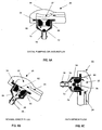
- peripheral flow channels 80 of the base section 34 can be made more tortuous with surface features such as helical ridges 86 as illustrated in FIG. 6A which shows the flow dynamics during distal pumping or anti-reflux.
- the helical ridges 86 within the peripheral flow channels 80 provide the shunt system 10 with higher resistance and even more anti-siphoning capabilities.
- FIG. 6B shows the flow dynamics during normal erect flow
- FIG. 6C shows the flow dynamics during anti-siphon flow in which fluid traveling distally is forced through the tortuous path of the peripheral flow channels 80 and is thereby drained from the shunt system 10 at a reduced rate.
- FIG. 6D shows the flow dynamics during prone flow, or during distal pumping.
- FIG. 6E shows the use of an endoscope 90 with the present shunt system 10 during endoscopic placement or ventricular injection.
- the present invention also provides an instrument 100 for assembling the inflow catheter 40 quickly and easily to the shunt device 20.
- the instrument 100 has a first arm 110 having a proximal end 112 and a distal end 114 including a handle portion 118. Pivotally connected to the first arm 110 at pin 130 is a second arm 120 having a proximal end 122 and a distal end 124 including a handle portion 128.
- the proximal end 112 of the first arm 110 includes a gripping section 116 that is configured to hold a portion of the housing 12. As illustrated in FIG. 7, the gripping portion 116 is configured to seat against the domed cap 14 of the housing 12.
- the proximal end 122 of the second arm also includes a platform section 126 that is configured to sit around the inflow catheter 40 and against the retaining ring 52 while resting on the patient's scalp. Upon compressing the handle portions 118, 128 together, the gripping section 116 and platform section 126 advance towards each other, in the process forcing the retaining ring 52 up towards the first, attachment end 42 of the inflow catheter 40.
- the platform section 126 is configured to slide along the inflow catheter 40. The use of the instrument 100 to connect these components enables the retaining ring 52 to slide over the attachment end 42 of the ventricular catheter 40 and over the flange 38 of the connector 36 without over advancement.
Landscapes
- Health & Medical Sciences (AREA)
- Engineering & Computer Science (AREA)
- Biomedical Technology (AREA)
- Neurology (AREA)
- Ophthalmology & Optometry (AREA)
- Otolaryngology (AREA)
- Anesthesiology (AREA)
- Heart & Thoracic Surgery (AREA)
- Hematology (AREA)
- Life Sciences & Earth Sciences (AREA)
- Animal Behavior & Ethology (AREA)
- General Health & Medical Sciences (AREA)
- Public Health (AREA)
- Veterinary Medicine (AREA)
- External Artificial Organs (AREA)
- Endoscopes (AREA)
- Infusion, Injection, And Reservoir Apparatuses (AREA)
- Surgical Instruments (AREA)
Applications Claiming Priority (2)
| Application Number | Priority Date | Filing Date | Title |
|---|---|---|---|
| US400730 | 2003-03-27 | ||
| US10/400,730 US7235060B2 (en) | 2003-03-27 | 2003-03-27 | Hydrocephalus shunt system with endoscopic placement features |
Publications (2)
| Publication Number | Publication Date |
|---|---|
| EP1462144A1 true EP1462144A1 (de) | 2004-09-29 |
| EP1462144B1 EP1462144B1 (de) | 2008-07-30 |
Family
ID=32824995
Family Applications (1)
| Application Number | Title | Priority Date | Filing Date |
|---|---|---|---|
| EP04251799A Expired - Lifetime EP1462144B1 (de) | 2003-03-27 | 2004-03-26 | Hydrocephalus-Ableitvorrichtung mit Endoskop-Platzierungsmöglichkeit |
Country Status (9)
| Country | Link |
|---|---|
| US (1) | US7235060B2 (de) |
| EP (1) | EP1462144B1 (de) |
| JP (1) | JP4566595B2 (de) |
| AT (1) | ATE402730T1 (de) |
| AU (1) | AU2004200960B2 (de) |
| BR (1) | BRPI0401080B1 (de) |
| CA (1) | CA2462367C (de) |
| DE (1) | DE602004015358D1 (de) |
| ES (1) | ES2309462T3 (de) |
Cited By (1)
| Publication number | Priority date | Publication date | Assignee | Title |
|---|---|---|---|---|
| WO2011076382A1 (de) * | 2009-12-23 | 2011-06-30 | Christoph Miethke Gmbh & Co Kg | Implantierbares shuntsystem |
Families Citing this family (31)
| Publication number | Priority date | Publication date | Assignee | Title |
|---|---|---|---|---|
| US9694166B2 (en) | 2002-03-26 | 2017-07-04 | Medtronics Ps Medical, Inc. | Method of draining cerebrospinal fluid |
| AU2003262938A1 (en) | 2002-08-27 | 2004-03-19 | Amir Belson | Embolic protection device |
| US20060111688A1 (en) * | 2004-11-22 | 2006-05-25 | Kraus Robert G | Ventriculostomy reservoir |
| US8333728B2 (en) * | 2005-12-01 | 2012-12-18 | Medtronic, Inc. | Implantable cerebrospinal fluid flow device and method of controlling flow of cerebrospinal fluid |
| US20070260222A1 (en) * | 2006-05-08 | 2007-11-08 | Kraus Robert G | Catheter having reinforcing rings and method of use |
| US9107734B2 (en) | 2006-11-29 | 2015-08-18 | Emboline, Inc. | Embolic protection device |
| US8075531B2 (en) * | 2008-07-16 | 2011-12-13 | Marvao Medical Ltd. | Modular implantable medical device |
| DE102009015229B4 (de) | 2009-04-01 | 2012-10-18 | Charité - Universitätsmedizin Berlin | Vorrichtung zum Führen eines Ventrikelkatheters beim Implantieren |
| JP5511486B2 (ja) * | 2010-04-26 | 2014-06-04 | 康雄 藍原 | 水頭症治療用シャントバルブ |
| US9492265B2 (en) | 2012-01-06 | 2016-11-15 | Emboline, Inc. | Integrated embolic protection devices |
| CA2898881C (en) | 2013-01-22 | 2021-01-05 | Alcyone Lifesciences, Inc. | Systems and methods for shunting fluid |
| EP2968730B1 (de) | 2013-03-15 | 2019-01-09 | Bitol Designs, LLC | Okklusionsresistenter katheter und verfahren zur verwendung |
| CA3124754C (en) | 2013-03-15 | 2023-08-15 | Children's Medical Center Corporation | Shunt flusher |
| AU2015247353B2 (en) | 2014-04-18 | 2020-07-09 | Anuncia, Inc | Systems and methods for shunting fluid |
| US10034742B2 (en) | 2014-10-23 | 2018-07-31 | Medos International Sarl | Biceps tenodesis implants and delivery tools |
| US10076374B2 (en) | 2014-10-23 | 2018-09-18 | Medos International Sárl | Biceps tenodesis delivery tools |
| US10856966B2 (en) | 2014-10-23 | 2020-12-08 | Medos International Sarl | Biceps tenodesis implants and delivery tools |
| US10729419B2 (en) | 2014-10-23 | 2020-08-04 | Medos International Sarl | Biceps tenodesis implants and delivery tools |
| US10751161B2 (en) | 2014-10-23 | 2020-08-25 | Medos International Sárl | Biceps tenodesis anchor implants |
| US11135350B2 (en) * | 2015-01-27 | 2021-10-05 | Stacey JACOVINI | Catheter anchor drain |
| US9693856B2 (en) | 2015-04-22 | 2017-07-04 | DePuy Synthes Products, LLC | Biceps repair device |
| US10617509B2 (en) | 2015-12-29 | 2020-04-14 | Emboline, Inc. | Multi-access intraprocedural embolic protection device |
| US10231823B2 (en) | 2016-04-08 | 2019-03-19 | Medos International Sarl | Tenodesis implants and tools |
| US10231824B2 (en) | 2016-04-08 | 2019-03-19 | Medos International Sárl | Tenodesis anchoring systems and tools |
| US12201789B2 (en) * | 2016-05-24 | 2025-01-21 | Abbey Lenore | Ventriculostomy patch system and method |
| ES3009906T3 (en) * | 2016-10-13 | 2025-03-31 | Anuncia Inc | Shunt flushers |
| US10485457B2 (en) * | 2017-03-10 | 2019-11-26 | National Guard Health Affairs | Device connectable to a dialysis catheter for in situ analysis |
| US11045632B2 (en) | 2017-04-24 | 2021-06-29 | Longeviti Neuro Solutions Llc | Cerebral spinal fluid shunt plug |
| US12569655B2 (en) | 2017-04-24 | 2026-03-10 | Longeviti Neuro Solutions, Inc. | Cerebral spinal fluid shunt plug |
| US11439798B2 (en) * | 2017-04-24 | 2022-09-13 | Longeviti Neuro Solutions Llc | Cerebral spinal fluid shunt plug |
| CN113677296B (zh) | 2019-02-13 | 2024-12-31 | 艾姆伯莱恩公司 | 具有整合的栓塞防护装置的导管 |
Citations (7)
| Publication number | Priority date | Publication date | Assignee | Title |
|---|---|---|---|---|
| US4578057A (en) * | 1984-08-31 | 1986-03-25 | Cordis Corporation | Ventricular right angle connector and system |
| DE3603463A1 (de) * | 1986-02-05 | 1987-08-06 | Plastik Fuer Die Medizin Pfm | Ventilschleuse fuer medizinische zwecke |
| EP0270205A2 (de) * | 1986-12-02 | 1988-06-08 | CODMAN & SHURTLEFF INC. | Gerät zum Übertragen von Körperflüssigkeiten |
| EP0366389A2 (de) * | 1988-10-24 | 1990-05-02 | Btg International Limited | Dialysesystem |
| US5176627A (en) * | 1990-05-15 | 1993-01-05 | Pudenz-Schulte Medical Research Corporation | Implantable fluid flow control device having two-piece base, and assembly process |
| US5304114A (en) * | 1991-05-15 | 1994-04-19 | Cosman Eric R | Shunt valve system |
| US5385541A (en) * | 1992-04-24 | 1995-01-31 | Loma Linda University Medical Center | Cerebrospinal fluid shunt capable of minimal invasive revision |
Family Cites Families (23)
| Publication number | Priority date | Publication date | Assignee | Title |
|---|---|---|---|---|
| US3886948A (en) * | 1972-08-14 | 1975-06-03 | Hakim Co Ltd | Ventricular shunt having a variable pressure valve |
| US3827439A (en) * | 1972-10-30 | 1974-08-06 | Heyer Schulte Corp | Plug valve for physiological shunt systems |
| US4332255A (en) * | 1979-01-10 | 1982-06-01 | Hakim Company Limited | Shunt valve |
| US4387715A (en) * | 1980-09-23 | 1983-06-14 | Hakim Company Limited | Shunt valve |
| US4551128A (en) * | 1983-05-11 | 1985-11-05 | Salomon Hakim | Cerebrospinal fluid shunt valve |
| US4560375A (en) * | 1983-06-30 | 1985-12-24 | Pudenz-Schulte Medical Research Corp. | Flow control valve |
| US4636194A (en) * | 1983-06-30 | 1987-01-13 | Pudenz-Schulte Medical Research Corp. | Burr-hole flow control valve |
| US4615691A (en) * | 1983-12-08 | 1986-10-07 | Salomon Hakim | Surgically-implantable stepping motor |
| US4595390A (en) * | 1983-07-21 | 1986-06-17 | Salomon Hakim | Magnetically-adjustable cerebrospinal fluid shunt valve |
| US4772257A (en) * | 1983-12-08 | 1988-09-20 | Salomon Hakim | External programmer for magnetically-adjustable cerebrospinal fluid shunt valve |
| US4963133A (en) * | 1987-12-31 | 1990-10-16 | Pharmacia Deltec, Inc. | Catheter attachment system |
| US4995856A (en) * | 1989-06-14 | 1991-02-26 | Pudenz-Schulte Medical Research Corporation | Ventriculostomy reservoir |
| US5167615A (en) * | 1990-05-15 | 1992-12-01 | Pudenz-Schulte Medical Research Corporation | Flow control device having selectable alternative fluid pathways |
| EP0600413A3 (de) * | 1992-11-30 | 1995-04-05 | Neuro Navigational Corp | Neuroendoskop mit Nebenschlusscharakteristik. |
| US5387188A (en) * | 1993-05-10 | 1995-02-07 | Pudenz-Schulte Medical Research Corporation | Pulsatile flow-accommodating fluid shunt |
| JP3309568B2 (ja) | 1994-05-16 | 2002-07-29 | 富士写真光機株式会社 | 内視鏡の処置具挿通チャンネル固定機構 |
| US5713858A (en) * | 1995-04-28 | 1998-02-03 | Medtronic, Inc. | Permanently implantable guiding catheter |
| US5662600A (en) * | 1995-09-29 | 1997-09-02 | Pudenz-Schulte Medical Research Corporation | Burr-hole flow control device |
| US5637083A (en) * | 1996-01-19 | 1997-06-10 | Pudenz-Schulte Medical Research Corporation | Implantable adjustable fluid flow control valve |
| JP3169547B2 (ja) | 1996-02-28 | 2001-05-28 | 住友ベークライト株式会社 | 薬液注入ポート |
| US5928182A (en) * | 1997-07-02 | 1999-07-27 | Johnson & Johnson Professional, Inc. | Pediatric programmable hydrocephalus valve |
| US6203513B1 (en) * | 1997-11-20 | 2001-03-20 | Optonol Ltd. | Flow regulating implant, method of manufacture, and delivery device |
| ES2228108T3 (es) * | 1998-09-17 | 2005-04-01 | Adeva Medical Gesellschaft Fur Entwicklung Und Vertrieb Von Medizinischen Implantat-Artikeln Mbh | Dispositivo para la insercion de una valvula de derivacion en una derivacion entre el esofago y la traquea. |
-
2003
- 2003-03-27 US US10/400,730 patent/US7235060B2/en not_active Expired - Lifetime
-
2004
- 2004-03-04 AU AU2004200960A patent/AU2004200960B2/en not_active Ceased
- 2004-03-26 ES ES04251799T patent/ES2309462T3/es not_active Expired - Lifetime
- 2004-03-26 AT AT04251799T patent/ATE402730T1/de not_active IP Right Cessation
- 2004-03-26 DE DE602004015358T patent/DE602004015358D1/de not_active Expired - Lifetime
- 2004-03-26 BR BRPI0401080-9A patent/BRPI0401080B1/pt not_active IP Right Cessation
- 2004-03-26 EP EP04251799A patent/EP1462144B1/de not_active Expired - Lifetime
- 2004-03-26 JP JP2004092755A patent/JP4566595B2/ja not_active Expired - Fee Related
- 2004-03-29 CA CA2462367A patent/CA2462367C/en not_active Expired - Fee Related
Patent Citations (7)
| Publication number | Priority date | Publication date | Assignee | Title |
|---|---|---|---|---|
| US4578057A (en) * | 1984-08-31 | 1986-03-25 | Cordis Corporation | Ventricular right angle connector and system |
| DE3603463A1 (de) * | 1986-02-05 | 1987-08-06 | Plastik Fuer Die Medizin Pfm | Ventilschleuse fuer medizinische zwecke |
| EP0270205A2 (de) * | 1986-12-02 | 1988-06-08 | CODMAN & SHURTLEFF INC. | Gerät zum Übertragen von Körperflüssigkeiten |
| EP0366389A2 (de) * | 1988-10-24 | 1990-05-02 | Btg International Limited | Dialysesystem |
| US5176627A (en) * | 1990-05-15 | 1993-01-05 | Pudenz-Schulte Medical Research Corporation | Implantable fluid flow control device having two-piece base, and assembly process |
| US5304114A (en) * | 1991-05-15 | 1994-04-19 | Cosman Eric R | Shunt valve system |
| US5385541A (en) * | 1992-04-24 | 1995-01-31 | Loma Linda University Medical Center | Cerebrospinal fluid shunt capable of minimal invasive revision |
Non-Patent Citations (2)
| Title |
|---|
| PATENT ABSTRACTS OF JAPAN vol. 1996, no. 03 29 March 1996 (1996-03-29) * |
| PATENT ABSTRACTS OF JAPAN vol. 1998, no. 01 30 January 1998 (1998-01-30) * |
Cited By (2)
| Publication number | Priority date | Publication date | Assignee | Title |
|---|---|---|---|---|
| WO2011076382A1 (de) * | 2009-12-23 | 2011-06-30 | Christoph Miethke Gmbh & Co Kg | Implantierbares shuntsystem |
| US8870809B2 (en) | 2009-12-23 | 2014-10-28 | Christoph Miethke Gmbh & Co Kg | Implantable hydrocephalus shunt system |
Also Published As
| Publication number | Publication date |
|---|---|
| BRPI0401080A (pt) | 2004-12-14 |
| BRPI0401080B1 (pt) | 2014-02-18 |
| DE602004015358D1 (de) | 2008-09-11 |
| EP1462144B1 (de) | 2008-07-30 |
| JP2004290678A (ja) | 2004-10-21 |
| ES2309462T3 (es) | 2008-12-16 |
| US7235060B2 (en) | 2007-06-26 |
| CA2462367A1 (en) | 2004-09-27 |
| CA2462367C (en) | 2012-01-03 |
| US20040193094A1 (en) | 2004-09-30 |
| ATE402730T1 (de) | 2008-08-15 |
| AU2004200960B2 (en) | 2010-06-10 |
| AU2004200960A1 (en) | 2004-10-14 |
| JP4566595B2 (ja) | 2010-10-20 |
Similar Documents
| Publication | Publication Date | Title |
|---|---|---|
| US7235060B2 (en) | Hydrocephalus shunt system with endoscopic placement features | |
| US8043247B1 (en) | Subarachnoid epidural shunt | |
| JP6956433B2 (ja) | 水頭症の治療システムおよび方法 | |
| US7699800B2 (en) | Multi-catheter insertion device and method | |
| EP1485146B1 (de) | Vesikel-shunt zur drainage von überschüssiger flüssigkeit | |
| JP4309649B2 (ja) | 脳脊髄液シャント装置および水頭症治療方法 | |
| US20140012180A1 (en) | Peritoneal drain and infusion | |
| US20140336559A1 (en) | Endovascular cerebrospinal fluid shunt | |
| JP2004534590A (ja) | クモ膜下腔に誘導する方法および装置 | |
| JP2004033773A (ja) | シャント弁システムおよびロックアセンブリ | |
| AU2004202487B2 (en) | Needle guard having inherent probe directing features | |
| WO2022087369A1 (en) | Catheter systems | |
| US20060111688A1 (en) | Ventriculostomy reservoir | |
| JP2001513000A (ja) | 血管アクセスを確立するための方法およびシステム | |
| JP2001509049A (ja) | 移植可能な調整自在流体流量制御弁 | |
| US9220877B2 (en) | Multi-branched anti-reflux valve | |
| US20160296736A1 (en) | Ventriculoperitoneal shunt with distal balloon |
Legal Events
| Date | Code | Title | Description |
|---|---|---|---|
| PUAI | Public reference made under article 153(3) epc to a published international application that has entered the european phase |
Free format text: ORIGINAL CODE: 0009012 |
|
| AK | Designated contracting states |
Kind code of ref document: A1 Designated state(s): AT BE BG CH CY CZ DE DK EE ES FI FR GB GR HU IE IT LI LU MC NL PL PT RO SE SI SK TR |
|
| AX | Request for extension of the european patent |
Extension state: AL LT LV MK |
|
| 17P | Request for examination filed |
Effective date: 20050307 |
|
| AKX | Designation fees paid |
Designated state(s): AT BE BG CH CY CZ DE DK EE ES FI FR GB GR HU IE IT LI LU MC NL PL PT RO SE SI SK TR |
|
| 17Q | First examination report despatched |
Effective date: 20050512 |
|
| GRAP | Despatch of communication of intention to grant a patent |
Free format text: ORIGINAL CODE: EPIDOSNIGR1 |
|
| GRAS | Grant fee paid |
Free format text: ORIGINAL CODE: EPIDOSNIGR3 |
|
| GRAA | (expected) grant |
Free format text: ORIGINAL CODE: 0009210 |
|
| AK | Designated contracting states |
Kind code of ref document: B1 Designated state(s): AT BE BG CH CY CZ DE DK EE ES FI FR GB GR HU IE IT LI LU MC NL PL PT RO SE SI SK TR |
|
| REG | Reference to a national code |
Ref country code: GB Ref legal event code: FG4D |
|
| REG | Reference to a national code |
Ref country code: CH Ref legal event code: EP |
|
| REG | Reference to a national code |
Ref country code: CH Ref legal event code: NV Representative=s name: E. BLUM & CO. AG PATENT- UND MARKENANWAELTE VSP |
|
| REF | Corresponds to: |
Ref document number: 602004015358 Country of ref document: DE Date of ref document: 20080911 Kind code of ref document: P |
|
| REG | Reference to a national code |
Ref country code: IE Ref legal event code: FG4D |
|
| REG | Reference to a national code |
Ref country code: SE Ref legal event code: TRGR |
|
| REG | Reference to a national code |
Ref country code: ES Ref legal event code: FG2A Ref document number: 2309462 Country of ref document: ES Kind code of ref document: T3 |
|
| PG25 | Lapsed in a contracting state [announced via postgrant information from national office to epo] |
Ref country code: PT Free format text: LAPSE BECAUSE OF FAILURE TO SUBMIT A TRANSLATION OF THE DESCRIPTION OR TO PAY THE FEE WITHIN THE PRESCRIBED TIME-LIMIT Effective date: 20081230 Ref country code: NL Free format text: LAPSE BECAUSE OF FAILURE TO SUBMIT A TRANSLATION OF THE DESCRIPTION OR TO PAY THE FEE WITHIN THE PRESCRIBED TIME-LIMIT Effective date: 20080730 |
|
| PG25 | Lapsed in a contracting state [announced via postgrant information from national office to epo] |
Ref country code: FI Free format text: LAPSE BECAUSE OF FAILURE TO SUBMIT A TRANSLATION OF THE DESCRIPTION OR TO PAY THE FEE WITHIN THE PRESCRIBED TIME-LIMIT Effective date: 20080730 Ref country code: SI Free format text: LAPSE BECAUSE OF FAILURE TO SUBMIT A TRANSLATION OF THE DESCRIPTION OR TO PAY THE FEE WITHIN THE PRESCRIBED TIME-LIMIT Effective date: 20080730 Ref country code: AT Free format text: LAPSE BECAUSE OF FAILURE TO SUBMIT A TRANSLATION OF THE DESCRIPTION OR TO PAY THE FEE WITHIN THE PRESCRIBED TIME-LIMIT Effective date: 20080730 Ref country code: BG Free format text: LAPSE BECAUSE OF FAILURE TO SUBMIT A TRANSLATION OF THE DESCRIPTION OR TO PAY THE FEE WITHIN THE PRESCRIBED TIME-LIMIT Effective date: 20081030 |
|
| PG25 | Lapsed in a contracting state [announced via postgrant information from national office to epo] |
Ref country code: BE Free format text: LAPSE BECAUSE OF FAILURE TO SUBMIT A TRANSLATION OF THE DESCRIPTION OR TO PAY THE FEE WITHIN THE PRESCRIBED TIME-LIMIT Effective date: 20080730 |
|
| PG25 | Lapsed in a contracting state [announced via postgrant information from national office to epo] |
Ref country code: DK Free format text: LAPSE BECAUSE OF FAILURE TO SUBMIT A TRANSLATION OF THE DESCRIPTION OR TO PAY THE FEE WITHIN THE PRESCRIBED TIME-LIMIT Effective date: 20080730 Ref country code: EE Free format text: LAPSE BECAUSE OF FAILURE TO SUBMIT A TRANSLATION OF THE DESCRIPTION OR TO PAY THE FEE WITHIN THE PRESCRIBED TIME-LIMIT Effective date: 20080730 |
|
| PG25 | Lapsed in a contracting state [announced via postgrant information from national office to epo] |
Ref country code: SK Free format text: LAPSE BECAUSE OF FAILURE TO SUBMIT A TRANSLATION OF THE DESCRIPTION OR TO PAY THE FEE WITHIN THE PRESCRIBED TIME-LIMIT Effective date: 20080730 Ref country code: RO Free format text: LAPSE BECAUSE OF FAILURE TO SUBMIT A TRANSLATION OF THE DESCRIPTION OR TO PAY THE FEE WITHIN THE PRESCRIBED TIME-LIMIT Effective date: 20080730 Ref country code: CZ Free format text: LAPSE BECAUSE OF FAILURE TO SUBMIT A TRANSLATION OF THE DESCRIPTION OR TO PAY THE FEE WITHIN THE PRESCRIBED TIME-LIMIT Effective date: 20080730 |
|
| PLBE | No opposition filed within time limit |
Free format text: ORIGINAL CODE: 0009261 |
|
| STAA | Information on the status of an ep patent application or granted ep patent |
Free format text: STATUS: NO OPPOSITION FILED WITHIN TIME LIMIT |
|
| 26N | No opposition filed |
Effective date: 20090506 |
|
| PG25 | Lapsed in a contracting state [announced via postgrant information from national office to epo] |
Ref country code: MC Free format text: LAPSE BECAUSE OF NON-PAYMENT OF DUE FEES Effective date: 20090331 |
|
| PG25 | Lapsed in a contracting state [announced via postgrant information from national office to epo] |
Ref country code: IE Free format text: LAPSE BECAUSE OF NON-PAYMENT OF DUE FEES Effective date: 20090326 |
|
| PG25 | Lapsed in a contracting state [announced via postgrant information from national office to epo] |
Ref country code: PL Free format text: LAPSE BECAUSE OF FAILURE TO SUBMIT A TRANSLATION OF THE DESCRIPTION OR TO PAY THE FEE WITHIN THE PRESCRIBED TIME-LIMIT Effective date: 20080730 |
|
| PG25 | Lapsed in a contracting state [announced via postgrant information from national office to epo] |
Ref country code: GR Free format text: LAPSE BECAUSE OF FAILURE TO SUBMIT A TRANSLATION OF THE DESCRIPTION OR TO PAY THE FEE WITHIN THE PRESCRIBED TIME-LIMIT Effective date: 20081031 |
|
| PG25 | Lapsed in a contracting state [announced via postgrant information from national office to epo] |
Ref country code: LU Free format text: LAPSE BECAUSE OF NON-PAYMENT OF DUE FEES Effective date: 20090326 |
|
| PG25 | Lapsed in a contracting state [announced via postgrant information from national office to epo] |
Ref country code: HU Free format text: LAPSE BECAUSE OF FAILURE TO SUBMIT A TRANSLATION OF THE DESCRIPTION OR TO PAY THE FEE WITHIN THE PRESCRIBED TIME-LIMIT Effective date: 20090131 |
|
| PG25 | Lapsed in a contracting state [announced via postgrant information from national office to epo] |
Ref country code: TR Free format text: LAPSE BECAUSE OF FAILURE TO SUBMIT A TRANSLATION OF THE DESCRIPTION OR TO PAY THE FEE WITHIN THE PRESCRIBED TIME-LIMIT Effective date: 20080730 |
|
| PG25 | Lapsed in a contracting state [announced via postgrant information from national office to epo] |
Ref country code: CY Free format text: LAPSE BECAUSE OF FAILURE TO SUBMIT A TRANSLATION OF THE DESCRIPTION OR TO PAY THE FEE WITHIN THE PRESCRIBED TIME-LIMIT Effective date: 20080730 |
|
| REG | Reference to a national code |
Ref country code: FR Ref legal event code: PLFP Year of fee payment: 13 |
|
| REG | Reference to a national code |
Ref country code: FR Ref legal event code: PLFP Year of fee payment: 14 |
|
| REG | Reference to a national code |
Ref country code: FR Ref legal event code: PLFP Year of fee payment: 15 |
|
| PGFP | Annual fee paid to national office [announced via postgrant information from national office to epo] |
Ref country code: GB Payment date: 20180321 Year of fee payment: 15 Ref country code: CH Payment date: 20180314 Year of fee payment: 15 Ref country code: DE Payment date: 20180313 Year of fee payment: 15 |
|
| PGFP | Annual fee paid to national office [announced via postgrant information from national office to epo] |
Ref country code: SE Payment date: 20180313 Year of fee payment: 15 Ref country code: FR Payment date: 20180222 Year of fee payment: 15 Ref country code: IT Payment date: 20180321 Year of fee payment: 15 |
|
| PGFP | Annual fee paid to national office [announced via postgrant information from national office to epo] |
Ref country code: ES Payment date: 20180402 Year of fee payment: 15 |
|
| REG | Reference to a national code |
Ref country code: GB Ref legal event code: 732E Free format text: REGISTERED BETWEEN 20180712 AND 20180718 |
|
| REG | Reference to a national code |
Ref country code: GB Ref legal event code: 732E Free format text: REGISTERED BETWEEN 20180719 AND 20180725 |
|
| REG | Reference to a national code |
Ref country code: DE Ref legal event code: R082 Ref document number: 602004015358 Country of ref document: DE Representative=s name: MUELLER-BORE & PARTNER PATENTANWAELTE PARTG MB, DE Ref country code: DE Ref legal event code: R081 Ref document number: 602004015358 Country of ref document: DE Owner name: INTEGRA LIFESCIENCES SWITZERLAND SARL, CH Free format text: FORMER OWNER: CODMAN & SHURTLEFF, INC., RAYNHAM, MASS., US |
|
| REG | Reference to a national code |
Ref country code: CH Ref legal event code: PUE Owner name: DEPUY SPINE, LLC, US Free format text: FORMER OWNER: CODMAN AND SHURTLEFF, INC., US Ref country code: CH Ref legal event code: PUE Owner name: INTEGRA LIFESCIENCES SWITZERLAND SARL, CH Free format text: FORMER OWNER: DEPUY SYNTHES PRODUCTS, INC., US Ref country code: CH Ref legal event code: PUE Owner name: DEPUY SYNTHES PRODUCTS, INC., US Free format text: FORMER OWNER: DEPUY SPINE, LLC, US |
|
| REG | Reference to a national code |
Ref country code: DE Ref legal event code: R119 Ref document number: 602004015358 Country of ref document: DE |
|
| REG | Reference to a national code |
Ref country code: SE Ref legal event code: EUG |
|
| PG25 | Lapsed in a contracting state [announced via postgrant information from national office to epo] |
Ref country code: SE Free format text: LAPSE BECAUSE OF NON-PAYMENT OF DUE FEES Effective date: 20190327 |
|
| REG | Reference to a national code |
Ref country code: CH Ref legal event code: PL |
|
| GBPC | Gb: european patent ceased through non-payment of renewal fee |
Effective date: 20190326 |
|
| REG | Reference to a national code |
Ref country code: ES Ref legal event code: PC2A Owner name: INTEGRA LIFESCIENCES SWITZERLAND SARL Effective date: 20200102 |
|
| PG25 | Lapsed in a contracting state [announced via postgrant information from national office to epo] |
Ref country code: LI Free format text: LAPSE BECAUSE OF NON-PAYMENT OF DUE FEES Effective date: 20190331 Ref country code: CH Free format text: LAPSE BECAUSE OF NON-PAYMENT OF DUE FEES Effective date: 20190331 Ref country code: DE Free format text: LAPSE BECAUSE OF NON-PAYMENT OF DUE FEES Effective date: 20191001 Ref country code: GB Free format text: LAPSE BECAUSE OF NON-PAYMENT OF DUE FEES Effective date: 20190326 |
|
| PG25 | Lapsed in a contracting state [announced via postgrant information from national office to epo] |
Ref country code: FR Free format text: LAPSE BECAUSE OF NON-PAYMENT OF DUE FEES Effective date: 20190331 Ref country code: IT Free format text: LAPSE BECAUSE OF NON-PAYMENT OF DUE FEES Effective date: 20190326 |
|
| REG | Reference to a national code |
Ref country code: ES Ref legal event code: FD2A Effective date: 20200728 |
|
| PG25 | Lapsed in a contracting state [announced via postgrant information from national office to epo] |
Ref country code: ES Free format text: LAPSE BECAUSE OF NON-PAYMENT OF DUE FEES Effective date: 20190327 |