EP1463003A1 - Gesicherte Frankiermaschine - Google Patents
Gesicherte Frankiermaschine Download PDFInfo
- Publication number
- EP1463003A1 EP1463003A1 EP03290755A EP03290755A EP1463003A1 EP 1463003 A1 EP1463003 A1 EP 1463003A1 EP 03290755 A EP03290755 A EP 03290755A EP 03290755 A EP03290755 A EP 03290755A EP 1463003 A1 EP1463003 A1 EP 1463003A1
- Authority
- EP
- European Patent Office
- Prior art keywords
- data
- printing
- unit
- franking machine
- franking
- Prior art date
- Legal status (The legal status is an assumption and is not a legal conclusion. Google has not performed a legal analysis and makes no representation as to the accuracy of the status listed.)
- Withdrawn
Links
Images


Classifications
-
- G—PHYSICS
- G07—CHECKING-DEVICES
- G07B—TICKET-ISSUING APPARATUS; FARE-REGISTERING APPARATUS; FRANKING APPARATUS
- G07B17/00—Franking apparatus
- G07B17/00185—Details internally of apparatus in a franking system, e.g. franking machine at customer or apparatus at post office
- G07B17/00314—Communication within apparatus, personal computer [PC] system, or server, e.g. between printhead and central unit in a franking machine
-
- G—PHYSICS
- G06—COMPUTING OR CALCULATING; COUNTING
- G06Q—INFORMATION AND COMMUNICATION TECHNOLOGY [ICT] SPECIALLY ADAPTED FOR ADMINISTRATIVE, COMMERCIAL, FINANCIAL, MANAGERIAL OR SUPERVISORY PURPOSES; SYSTEMS OR METHODS SPECIALLY ADAPTED FOR ADMINISTRATIVE, COMMERCIAL, FINANCIAL, MANAGERIAL OR SUPERVISORY PURPOSES, NOT OTHERWISE PROVIDED FOR
- G06Q20/00—Payment architectures, schemes or protocols
- G06Q20/38—Payment protocols; Details thereof
- G06Q20/382—Payment protocols; Details thereof insuring higher security of transaction
-
- G—PHYSICS
- G07—CHECKING-DEVICES
- G07B—TICKET-ISSUING APPARATUS; FARE-REGISTERING APPARATUS; FRANKING APPARATUS
- G07B17/00—Franking apparatus
- G07B17/00185—Details internally of apparatus in a franking system, e.g. franking machine at customer or apparatus at post office
- G07B17/00314—Communication within apparatus, personal computer [PC] system, or server, e.g. between printhead and central unit in a franking machine
- G07B2017/00322—Communication between components/modules/parts, e.g. printer, printhead, keyboard, conveyor or central unit
-
- G—PHYSICS
- G07—CHECKING-DEVICES
- G07B—TICKET-ISSUING APPARATUS; FARE-REGISTERING APPARATUS; FRANKING APPARATUS
- G07B17/00—Franking apparatus
- G07B17/00459—Details relating to mailpieces in a franking system
- G07B17/00508—Printing or attaching on mailpieces
- G07B2017/00516—Details of printing apparatus
- G07B2017/00524—Printheads
- G07B2017/00532—Inkjet
-
- G—PHYSICS
- G07—CHECKING-DEVICES
- G07B—TICKET-ISSUING APPARATUS; FARE-REGISTERING APPARATUS; FRANKING APPARATUS
- G07B17/00—Franking apparatus
- G07B17/00459—Details relating to mailpieces in a franking system
- G07B17/00508—Printing or attaching on mailpieces
- G07B2017/00612—Attaching item on mailpiece
- G07B2017/00629—Circuit, e.g. transponder
Definitions
- the invention relates in particular to a franking machine.
- this data is not secure, it is, for example, possible a fraudster to intercept them between the data generation unit and the unit even inside the printing unit itself. So where a postage mark with a value of X should be printed on a envelope, the fraudster can replace this mark with a mark postage of a value of Y which is greater than X.
- the management unit will not decrease by its counter of postage values delivered to the printing unit that a value of X when a higher value has actually been printed.
- a specific printing device such as, for example, a specific inkjet print cartridge which would include an internal data decryption circuit which would be made inaccessible from the outside.
- the invention relates to a franking machine comprising a postage data generation unit and a data printing unit connected to said generation unit data and receiving postage data therefrom, said printing unit comprising at least one data printing member, characterized in that the franking machine comprises means additional wireless communication between the printing unit and the generation of data for the identification of the printing device by the unit of data generation.
- the data generation unit is able to control the printing device and, in particular to verify his identity.
- the printing unit provides, for example, data authentication to the data generation unit in the case of a one-way communication.
- the data generation unit can also pick up in the printing device an identifier of the latter.
- the data generation unit may decide not to send a print order to the printing unit or to transmit the order to print data incorrect or incomplete postage.
- the generation unit can decide to send a blocking order to the printing body so that the latter stops printing the data.
- This aspect of the invention therefore does not require providing a specific connection between these elements for the implementation of the invention.
- wireless communication is carried out by radio waves.
- the printing member comprises at least an identification label which communicates data by radio waves of identification of the printing member to the data generation unit under the action of an electromagnetic field.
- the identification label is flexible, that is to say that it folds easily.
- the identification label includes a substrate fixed irremovably on the printing member and means for communication arranged on the substrate.
- the data generation unit includes an electromagnetic field source.
- the data generation unit includes a circuit for receiving identification data.
- the printing member is a cartridge inkjet printing machine comprising at least one printhead.
- the invention relates to a cartridge inkjet printing machine for printing data, characterized in that it includes at least one cartridge identification label which communicates identification data outside by radio waves, under the action of an electromagnetic field, the identification label comprising a substrate fixed on the cartridge and communication means arranged on the substrate.
- a print cartridge can be identified remotely without whether it requires physical contact or connection. This therefore allows just make sure the print cartridge is a cartridge authentic and not a cartridge which would have been replaced by a fraudster.
- This aspect of the invention is useful when sensitive data or must be transmitted to the print cartridge by a external data source, via the printing unit which incorporates the cartridge.
- radio wave identification label contributes to reliably securing this cartridge and thereby printing mechanism, without compromising technology printing and, in particular, without modifying the cartridge itself.
- the cartridge comprises a unit of data processing which analyzes a flow of print orders intended to control the print head of the cartridge, in order to authenticate the data to print.
- the processing unit comprises means checking the integrity of the data to be printed.
- the data processing unit miniaturized is integral with a flexible and thin printed circuit which is fixed cannot be removed from the print cartridge.
- the substrate of the identification label is permanently fixed to the cartridge, so that any attempt subsequent removal of the substrate damages the communication means of it.
- the identification label is flexible.
- the identification label contains main identification data.
- the identification label contains secondary identification data relating to the use of the cartridge in a postage meter.
- the invention also relates to using an inkjet print cartridge, as briefly described above, in a data printing unit.
- This aspect of the invention is particularly interesting in the field of franking machines which include a printing unit of data on a medium.
- the printing device is capable of decrypting the encrypted signature and therefore whether or not to authenticate the source of this data.
- the printing unit will stop printing the data if it has started or will allow its continuation by introducing wrong data.
- the printing member comprises means of authenticating postage data.
- the printing member comprises means of verifying the integrity of postage data.
- the printing member comprises at least an identification label of said printing member which communicates by radio waves, to the data generation unit, identification data of this organ under the action of an electromagnetic field.
- the identification label includes a substrate fixed irremovably on the printing member and means for communication arranged on the substrate.
- the data generation unit includes a circuit for receiving identification data.
- the data generation unit includes an electromagnetic field source.
- the means for decrypting the organ have prior knowledge of said identification data printing device.
- the printing member comprises a unit data processing which includes the means of decryption.
- the decryption means are integral a flexible and thin printed circuit which is fixedly mounted on the member printing.
- the data processing unit is integral with a flexible and thin printed circuit which is fixedly mounted on the printing organ.
- the printing member is a cartridge inkjet printing machine comprising at least one printhead.
- FIG. 1 represents in a way schematic the general architecture of a franking machine 10 according to the invention.
- This machine generally comprises two entities: a unit for generating postage data 12 and a printing unit for data 14 which receives franking data from unit 12 with a view to their impression in the form, for example, of a postage mark 16 on an envelope 17.
- unit 12 also called meter (“meter” in English terminology)
- meter includes a central unit data processing device 18 which communicates with a module 20 comprising a cryptography circuit 22 containing the algorithm or algorithms necessary for data encryption, a fraud detection circuit 24 which aims, by example, to detect an attempt to open the machine cover franking, for example, by mechanical contacts or optics, and a CSP circuit 26 which is informed of an attempted fraud by the circuit 24 and then erases certain critical data such as as, for example, encryption keys or algorithms.
- a central unit data processing device 18 which communicates with a module 20 comprising a cryptography circuit 22 containing the algorithm or algorithms necessary for data encryption, a fraud detection circuit 24 which aims, by example, to detect an attempt to open the machine cover franking, for example, by mechanical contacts or optics, and a CSP circuit 26 which is informed of an attempted fraud by the circuit 24 and then erases certain critical data such as as, for example, encryption keys or algorithms.
- Unit 12 also includes a modem 28 which allows postal services to take a metering of the franking machine by via telephone communication, for billing purposes by example.
- the central unit 18 which in particular comprises a processor or microprocessor also communicates with a balance 30 used for weighing of the postal folds which will be franked.
- the device 32 which is, for example, a card electronic (PC option) to emulate the man-machine interface 36 (HMI) integrated in the franking machine 10 and which includes, so conventional, a keyboard and a screen not shown.
- PC option card electronic
- HMI man-machine interface 36
- the franking data generation unit 12 communicates with the printing unit 14 via a communication mode communication, for example, of wired type which relies on a connection 38 USB type.
- the central unit 18 communicates in particular with the module 20, the external devices 30, 32 and the human-machine interface 36 via of this type of connections.
- the printing unit 14 which is, for example, a printer includes a print control module 40 which receives from the unit 12 a postage data stream to be printed and an encrypted signature 42 and transforms the data received into a stream of print commands 44 which is then transmitted to one or more printing members 46, to printing of postage data in the form of the mark postage 16.
- a print control module 40 which receives from the unit 12 a postage data stream to be printed and an encrypted signature 42 and transforms the data received into a stream of print commands 44 which is then transmitted to one or more printing members 46, to printing of postage data in the form of the mark postage 16.
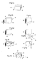
- the printing member 46 is a cartridge inkjet printing machine which has an ink tank 48 and a head 50 for printing data ( Figures 1 and 4a).
- the print commands of stream 44 are intended to control the printhead 50 for printing the postage mark 16 on support 17.
- the printing member 46 is made intelligent by the presence of a module 54 affixed to the latter and which will be described in more detail later.
- the franking machine 10 includes means additional wireless communication between the printing member 46 and the unit 12 for the identification by the latter of said printing member.
- the unit 12 comprises a transmission module 56 and the printing unit 14 comprises a reception module 58 affixed to the printing member 46.
- the wireless communication between the unit 12 and the printing member 46 is carried out by means of radio waves.
- the module 58 transmits to the unit 12 identification data of the printing organ.
- the module 58 is a label of identification of the printing unit which communicates by radio waves its identification data under the action of an electromagnetic field, the source is in module 56.
- the module 56 When the module 56 wishes to identify a printing member in order to to make sure that it is indeed an authorized printing device, it then generates a constant magnetic field intended for the module 58 of the organ 46 and then measures back, via a circuit reception, the variations generated by the module 58 on this magnetic field.
- the module 58 performs a kind of amplitude modulation of the electromagnetic signal.
- the measurement of the variations of the electromagnetic field allows obtain the identification data of the printing member and therefore whether or not to recognize the printing device which is nearby.
- This recognition procedure takes place before the unit of data generation 12 only transmits data to the printing unit 14 postage for printing.
- the frequency of the electromagnetic waves emitted by module 56 is, for example, 13.56 MHz.
- RFID This technology to communicate remotely and identify a element is known as RFID which means in terminology Anglo-Saxon “Radio Frequency IDentification” (identification by radio frequency).
- module 56 may wish to write data to the identification module 58 and, to do this, the amplitude modulation of electromagnetic signal is then generated directly by the module 56 itself.
- identification label 58 is known as Anglo-Saxon terminology under the term "RFID Tag".
- module 56 is, for example, made in the form of an electronic component marketed by the company Texas Instruments under the commercial reference “HF Reader System 6000 series S6700 Multi-protocol Transceiver IC ".
- Such a component also known as a transponder, manages the exchange of data and signals between the label 58 and the transponder itself.
- the identification label is, for example, marketed by the Texas Instruments company under the reference “Tag-it HF-1 Transponder Inlay Rectangle-Miniature ".
- This component has a memory space of 2 Kbits which is accessible in read and write mode and has a number unique identification (main identification data) for each component that is only accessible in read mode.
- the label identifier constitutes a unique identifier for the printing body itself.
- the identification label also contains data secondary identification which are, for example, relating to the use of the cartridge in a given application which is, in the exemplary embodiment described, a franking machine.
- data secondary identification may, for example, be own data to postage applications.
- Figure 2 illustrates a label identification used in the franking machine 10 of FIG. 1. It will be noted however, such a label intended to be affixed to an organ such as an inkjet print cartridge with a head printing can be used outside the field of postage meters, more generally in printing units which receive, in from external devices, confidential and / or sensitive data.
- the presence of the identification label on an organ printing of such a printing unit constitutes a security for printing confidential and / or sensitive data insofar as authorization to print such data will only be issued when the printing unit will have been unequivocally identified, via its identification tag, during a recognition procedure conducted between the source of confidential and / or sensitive data and said body printing.
- the identification label 58 includes very schematically a thin and flexible substrate 60, that is to say which folds easily, on which radio communication means are arranged, constituting the communication function of the identification label.
- the communication means consist of an integrated circuit 62 which performs the transmission and reception function and an antenna 64 which picks up the field magnetic.
- the antenna 64 is, for example, produced at the periphery of the substrate 60.
- FIGS 3a and 3b schematically illustrate the module 54 constituting the intelligence embedded on the printing device.
- the module 54 is in the form of a double printed circuit flexible face, that is to say which folds easily, thin and of which is made integral a miniaturized data processing unit 68 of small thickness.
- the total thickness of the thin circuit 66 and of the processing unit 68 is sufficiently low so that, when the module intelligent 54 is fixed on a standard inkjet print cartridge 46, as will be seen below with reference to FIGS. 4a to 4h, the space generated by the cartridge thus equipped does not call into question installing this cartridge in the standard printing unit to which it is intended.
- circuit 66 and unit 68 is, for example, less than 1.5 mm, which allows its integration on a very large number of inkjet print cartridges without changing the geometry of the cartridge and its holder.
- the thickness of the data processing unit 68 is, for example, close to 1 mm (example: 0.9 mm) and that of circuit 66 is, for example, less than 0.2 mm.
- circuit 66 and the unit 68 which is, for example, between 1.5 and 2 mm.
- the circuit 66 comprises on a front face a plurality of electrical contact pads 70a to 70k intended to communicate with the processing unit 68 via tracks respective conductors 72a to 72k.
- the contact pads 70a to 70k thus serve to receive the print control 40 of FIG. 1 the flow of print commands 44 and to transmit it to the processing unit 68.
- the circuit 66 includes a plurality of conductive tracks which leave from the processing unit 68 (part lower left) to reach the opposite face known as the rear of the double circuit face and which is shown in Figure 3b.
- the circuit 66 comprises on the rear face a plurality of pads electrical contacts 73a to 73k which are, on the one hand, connected to the processing unit 68 via respective conductive tracks 75a to 75k partially shown on the left-hand side of FIG. 3a and, on the other hand, intended to be in contact with the corresponding electrical contact pads 79 on the standard print cartridge 46 shown in Figure 4a.
- the processing unit 68 transmits these commands successively via the conductive tracks 75a to 75k, the electrical contact pads 73a to 73k, as well as the contact pads corresponding electrics provided on the print cartridge of FIG. 4a, to be finally transmitted to the print head of this cartridge, for the control of the printing operation.
- the flexible circuit 66 of FIG. 3a comprises two parts which are delimited by two notches 74 and 76 arranged opposite on two parallel longitudinal edges of the support and which define between these parts a fold line. This fold line will be used, as we will see later with reference to Figures 4e to 4h, installation of module 54 on two different areas of the outer surface of the cartridge printing.
- the printed circuit 66 has a first part 67 on which are provided with the electrical contact pads 70a to 70k and a second part 69 on which the processing unit 68 is mounted.
- the data processing unit 68 is performed in programmed logic, which reduces consumption energy of such a component.
- the flexible printed circuit is made of material PTF type polymer with a thickness approximately equal to 0.125 mm.
- the PTF technology used is a technology relatively economical which uses a polyester film for the dielectric and a silver conductive ink to produce the aforementioned conductive tracks.
- This technology allows for multilayer circuits.
- the data processing unit 68 is mounted on the printed circuit 66 by known techniques for integrating an electronic component on a circuit.
- the component protected by its case is then transferred to the circuit by a known technique and the connection pins of the housing are fixed on the conductive tracks of the circuit by a conductive adhesive, by example, isotropic.
- the type of printed circuit which is used according to the invention to be non-detachably attached to a print cartridge is, for example, a circuit of the type of those marketed by the company Parlex.
- FIG 4a schematically illustrates a cartridge 46 standard inkjet printing, for example, a cartridge marketed by Hewlett Packard under the commercial reference HPc665x.
- This cartridge comprises, in a known manner, inside, a reservoir ink and a print head 50 provided with nozzles for ejecting the ink on the print media.
- This cartridge also comprises, in a known manner, on its surface exterior, electrical contacts 79 mounted on a thin circuit affixed to the cartridge, the electrical contacts being intended to direct the signals of print command to the print head for nozzle control ink ejection.
- the cartridge jet printer 46 of Figure 4a is equipped with the label previously described (identification module 58 of Figures 1 and 2), for example, by definitive bonding of the latter to the external surface of the cartridge.
- the substrate 60 of the label identification is fixed in a non-removable manner on the cartridge, so that that any subsequent attempt to remove the substrate damages the means of communication 62, 64 arranged thereon.
- a person skilled in the art can carry out a non-removable fixing of the substrate. on the cartridge, for example, using commercially available glues adapted to the materials intended to be in contact and which make it possible to produce a particularly intimate contact between the substrate and the exterior surface of the cartridge ( Figures 4c and 4d).
- the identification label 58 may be of dimensions greater than those of a face 85 of the cartridge. In this case, provision is made, thanks to the flexibility of the label, for folding of it and position part of the label on side 85 and the other folded part on one of the adjacent faces 86 of the cartridge.
- the identification tag 58 is particularly thin, which allows its integration on the outer surface of the cartridge without modify its external dimensions in such a way that would causes the cartridge to be installed in a standard printing unit.
- the thickness constraints of the identification label are: same as those mentioned above for the intelligent module 54.
- the label has a thickness which is, for example, less than 1 mm.
- the printed circuit 66 of the Figure 3 is fixed in a non-removable manner on the outer surface of the cartridge to prevent any possibility of interposing an external element between this circuit and the cartridge itself.
- circuit 66 intimately on the outer surface of the cartridge, so that any attempt to removal by detachment from circuit 66 causes damage to the latter and therefore makes it impossible for a fraudster to use the cartridge.
- the second part 69 of the circuit thin print 66 on which the data processing unit 68 is mounted is first arranged on one of the outer faces 81 of the cartridge, while that the first part 67, on which the contact pads are arranged electric, is arranged on an adjacent face 83 of this cartridge (figures 4g and 4h).
- the second part 69 of the thin circuit 66 is arranged preferably on an area of the outer surface of the cartridge which, when this cartridge is integrated in a printing unit, cleaning with the elements constituting the printing unit sufficient space to accommodate the data processing unit 68.
- circuit 66 extends from the face 83 until it comes into contact with the opposite face 85 and the unit data processing 68 is positioned opposite this face.
- the identification label 58 must then be positioned on another free area of the outer surface of the print cartridge.
- modules 54 and 58 are used in the best possible way so that these modules can best match the available external surface of the cartridge.
- each module thus makes it possible to adapt to the cartridge geometry and the constraints linked to the installation of these cartridges in their holder of the printing unit.
- the arrangement of the thickest part of the intelligent module 54 of Figure 3 thus depends on the space left free around the cartridge when it is installed in a printing unit.
- the inkjet print cartridge 46 of Figure 4h is thus equipped with an identification module which allows the identification of this cartridge by an external device (source of confidential data and / or sensitive) and an intelligent module, these modules each representing a particular means of securing the cartridge.
- Such equipment fitted on a jet print cartridge commercially available standard ink is particularly advantageous insofar as it does not call into question the design thereof, nor its external dimensions.
- Securing data in the postage meter Figure 1 is first performed through authentication of the printing device 46 by the data generation unit 12.
- the unit 12 obtains identification data from the printing member 46 via the wireless communication mode described above.
- module 20 develops signing postage data using a method known mathematics.
- the encryption circuit 22 of the module 20 then proceeds encryption of the signature thus produced. For example, we use encryption known type 3DES.
- Such encryption implies possession by the issuer and by the receiver of different encryption keys with a length of 128 bits for the 3DES type encryption.
- This key must also be known to the issuer and therefore contained in the encryption circuit 22.
- This key is used by the transmitter 12 for data encryption and, for receiver 54, when decrypting this data.
- This key can be programmed when the module 54 is mounted on the print cartridge, or programmed directly into the print unit treatment 68 during the production of module 54.
- the unit 18 associates it, for example by concatenation, postage data and transmits all of these data which constitute stream 42 through the link of communication 38.
- FIG. 5 schematically illustrates different functional blocks contained in the data processing unit 68 of FIG. 3a.
- the data processing unit 68 receives the flow of print commands 44 of FIG. 1 and analyzes it in view, in particular, to authenticate the data to be printed.
- the energy that is needed to processing unit operation comes from the signal flow of print orders.
- the data processing unit could use a microprocessor provided that the energy taken off does not risk degrading the impression of data.
- the processing unit 68 comprises a self-supply block 92 and a clock generation block 94 which feed each of the blocks which go be described later with a specific clock frequency.
- a block 96 extracts the encrypted signature from the order flow 44 which reaches the data processing unit 68 and performs a decryption of this signature.
- the encryption key (s) are also known from the processing unit 68, either by programming made when the module 54 is manufactured, i.e. when it is affixed on the printing member 46.
- the decryption is carried out by the decryption block 98.
- the data processing unit 68 also includes a circuit 99 which includes an authentication block 100 which provides for authenticating the data to be printed from the analysis performed on the signature of the data decrypted postage.
- the block 104 authorizes the printing of data.
- block 104 decides not to authorize printing data or generating a postage mark incorrect and therefore unusable.
- the data processing unit 68 prints, for example, first a few lines of data postage and then analyzes some data that has been extracted from the feed print orders and, depending on the result of the analysis, authorizes whether or not to print the following lines and carry out an analysis again other data from the print order flow and so on.
- the data processing unit 68 also includes a non-volatile memory 106 which mainly function to store the dynamic values of the application like, for example, the date of manufacture of the cartridge ... and possibly store values generated by blocks 98, 100 and 102.
- FIG. 6 some of the elements constituting the data processing unit 68 of FIG. 5.
- the data processing unit 68 comprises a reception block 108 series including a buffer memory necessary for intermediate storage of a quantity of data extracted from the signal flow print order 44.
- part of the control signals is used to generate the self-supply (block 92) of the data processing 68.
- a block 110 for analyzing data extracted from the print order combining various functionalities provided by blocks 98, 100, 102 and 104 in Figure 5 provide a Cmd-decode signal.
- a circuit 112 comprising a logic switch is provided for selectively authorize the passage of an Xout signal, from a signal print command Xin, depending on the value of the command signal Cmd-decode.
- the Cmd-decode signal is produced for one or more lines of postage data and authorizes, for example, the passage and therefore printing a given number of lines of postage data intended to constitute the franking mark.
- circuit 112 constitutes a pattern which is repeated several times depending on the number of Xin signals from the signals of print order.
- the flow of print commands 114 from unit 68 is then transmitted to the print head 50 to control the print nozzles.
- Figure 7 schematically illustrates the principle self-supply provided in block 92 of Figure 6.
- the circuit 120 of FIG. 7 comprises a set 122 of several diodes (m) in parallel each receiving one of the signals command Cmd cartridge 0, ..., Cmd cartridge m which each correspond to data specific to a line of the image to be printed.
- the set of diodes 122 carry out a logic function of the type "OR" which authorizes the delivery of a signal when the state of this is 1.
- the control signal which is allowed to pass is then filtered in a filter 124 whose values of the components R, C are determined in function of the value of the "load" of the unit 68 circuit, this in order to allow the accumulation of energy.
- Figure 8 provides timing diagrams of unit 68 charge.
- the latter is generated (part a) by the detection of a first rising edge of a control signal Cmd cartridge x.
- this control signal goes to state 0
- the self-supply signal Vout loses a little energy (part b), but starts to grow again (part c) after detection a rising edge of the control signal according to Cmd cartridge x + k.
- control signals which are generated by the unit 12 and intended to drive the print head 50 may have an amplitude of the order of 20 V, which means that the processing unit 68 is rather realized in the form of a technology called high voltage.
- the heart of the unit 68 which is, for example, an integrated circuit specific application (ASIC) works, for example, with a voltage of 3.3 V or 5 V and incorporates a RAM or EEPROM type memory.
- ASIC integrated circuit specific application
Landscapes
- Engineering & Computer Science (AREA)
- Business, Economics & Management (AREA)
- Physics & Mathematics (AREA)
- General Physics & Mathematics (AREA)
- Accounting & Taxation (AREA)
- General Engineering & Computer Science (AREA)
- Computer Security & Cryptography (AREA)
- Computer Hardware Design (AREA)
- Finance (AREA)
- Strategic Management (AREA)
- General Business, Economics & Management (AREA)
- Theoretical Computer Science (AREA)
- Accessory Devices And Overall Control Thereof (AREA)
- Record Information Processing For Printing (AREA)
- Ink Jet (AREA)
Priority Applications (3)
| Application Number | Priority Date | Filing Date | Title |
|---|---|---|---|
| EP03290755A EP1463003A1 (de) | 2003-03-25 | 2003-03-25 | Gesicherte Frankiermaschine |
| US10/809,570 US8069123B2 (en) | 2003-03-25 | 2004-03-24 | Secure franking machine |
| CA002462469A CA2462469A1 (en) | 2003-03-25 | 2004-03-24 | A secure franking machine |
Applications Claiming Priority (1)
| Application Number | Priority Date | Filing Date | Title |
|---|---|---|---|
| EP03290755A EP1463003A1 (de) | 2003-03-25 | 2003-03-25 | Gesicherte Frankiermaschine |
Publications (1)
| Publication Number | Publication Date |
|---|---|
| EP1463003A1 true EP1463003A1 (de) | 2004-09-29 |
Family
ID=32799146
Family Applications (1)
| Application Number | Title | Priority Date | Filing Date |
|---|---|---|---|
| EP03290755A Withdrawn EP1463003A1 (de) | 2003-03-25 | 2003-03-25 | Gesicherte Frankiermaschine |
Country Status (3)
| Country | Link |
|---|---|
| US (1) | US8069123B2 (de) |
| EP (1) | EP1463003A1 (de) |
| CA (1) | CA2462469A1 (de) |
Families Citing this family (3)
| Publication number | Priority date | Publication date | Assignee | Title |
|---|---|---|---|---|
| US20070078796A1 (en) * | 2005-10-03 | 2007-04-05 | Roman Kresina | Weighing feeder |
| CN116981567B (zh) * | 2021-03-18 | 2025-12-30 | 利盟国际有限公司 | 选择性地阻止部件操作的方法和系统 |
| US11989737B2 (en) * | 2021-07-09 | 2024-05-21 | Lexmark International, Inc. | Methods and systems for determining the authenticity of a component |
Citations (6)
| Publication number | Priority date | Publication date | Assignee | Title |
|---|---|---|---|---|
| EP0718803A2 (de) * | 1994-12-22 | 1996-06-26 | Pitney Bowes Inc. | Identifizieren einer spezifischen Kombination von Gebührenabrechnungstresor und digitalem Drucker |
| FR2774494A1 (fr) * | 1998-01-30 | 1999-08-06 | Neopost Ind | Systeme d'affranchissement postal securise |
| US6164551A (en) * | 1997-10-29 | 2000-12-26 | Meto International Gmbh | Radio frequency identification transponder having non-encapsulated IC chip |
| GB2354735A (en) * | 1999-10-01 | 2001-04-04 | Hewlett Packard Co | Memory tag for a replaceable printer component |
| DE19954749A1 (de) * | 1999-11-14 | 2001-05-31 | Tally Computerdrucker Gmbh | Drucker mit austauschbaren Baugruppen, insbesondere Tintenbehälter, Abfalltintenbehälter, Tintendruckköpfen u.dgl. |
| US20020030714A1 (en) * | 1999-04-20 | 2002-03-14 | Walker Ray A. | Method and apparatus for transferring information between a replaceable consumable and a printing device |
Family Cites Families (21)
| Publication number | Priority date | Publication date | Assignee | Title |
|---|---|---|---|---|
| US4813912A (en) * | 1986-09-02 | 1989-03-21 | Pitney Bowes Inc. | Secured printer for a value printing system |
| US4802218A (en) * | 1986-11-26 | 1989-01-31 | Wright Technologies, L.P. | Automated transaction system |
| US4864618A (en) * | 1986-11-26 | 1989-09-05 | Wright Technologies, L.P. | Automated transaction system with modular printhead having print authentication feature |
| US5185866A (en) * | 1988-12-30 | 1993-02-09 | Pitney Bowes Inc. | Dual mode communication among plurality of processors using three distinct data channels each having different function and operations |
| AU3241795A (en) * | 1994-08-09 | 1996-03-07 | Encad, Inc. | Printer ink cartridge |
| US5812536A (en) * | 1995-07-05 | 1998-09-22 | Pitney Bowes Inc. | Secure accounting system employing RF communications for enhanced security and functionality |
| JPH0939265A (ja) * | 1995-07-29 | 1997-02-10 | Seiko Epson Corp | プリンタにおけるインクカートリッヂ並びにその識別装置 |
| US5799290A (en) * | 1995-12-27 | 1998-08-25 | Pitney Bowes Inc. | Method and apparatus for securely authorizing performance of a function in a distributed system such as a postage meter |
| GB9709050D0 (en) * | 1997-05-02 | 1997-06-25 | Neopost Ltd | Postage meter with removable print head |
| US6123410A (en) * | 1997-10-28 | 2000-09-26 | Hewlett-Packard Company | Scalable wide-array inkjet printhead and method for fabricating same |
| DE19748954A1 (de) * | 1997-10-29 | 1999-05-06 | Francotyp Postalia Gmbh | Verfahren für eine digital druckende Frankiermaschine zur Erzeugung und Überprüfung eines Sicherheitsabdruckes |
| WO2001037203A1 (en) * | 1999-11-16 | 2001-05-25 | United States Postal Service | Electromagnetic postal indicia and method of applying same |
| DE19958941B4 (de) * | 1999-11-26 | 2006-11-09 | Francotyp-Postalia Gmbh | Verfahren zum Schutz eines Gerätes vor einem Betreiben mit unzulässigem Verbrauchsmaterial |
| DE10011192A1 (de) * | 2000-03-08 | 2001-09-13 | Francotyp Postalia Gmbh | Frankiermaschine mit abgesichertem Druckkopf |
| DE10036345B4 (de) * | 2000-07-26 | 2005-07-07 | Francotyp-Postalia Ag & Co. Kg | Anordnung und Verfahren zur Datennachführung für Aufwärmzyklen von Tintenstrahldruckköpfen |
| US6934836B2 (en) * | 2000-10-06 | 2005-08-23 | Protasis Corporation | Fluid separation conduit cartridge with encryption capability |
| JP2004526589A (ja) * | 2001-01-09 | 2004-09-02 | イーストマン コダック カンパニー | インクジェットプリントヘッドの品質管理システムおよび方法 |
| US6978345B2 (en) * | 2001-05-15 | 2005-12-20 | Hewlett-Packard Development Company, L.P. | Self-mirroring high performance disk drive |
| US20020188860A1 (en) | 2001-06-12 | 2002-12-12 | Parry Travis J. | Automatic electronic identification self-check |
| US6961000B2 (en) * | 2001-07-05 | 2005-11-01 | Amerasia International Technology, Inc. | Smart tag data encoding method |
| FR2852886A1 (fr) * | 2003-03-25 | 2004-10-01 | Secap | Cartouche d'impression securisee |
-
2003
- 2003-03-25 EP EP03290755A patent/EP1463003A1/de not_active Withdrawn
-
2004
- 2004-03-24 US US10/809,570 patent/US8069123B2/en not_active Expired - Fee Related
- 2004-03-24 CA CA002462469A patent/CA2462469A1/en not_active Abandoned
Patent Citations (6)
| Publication number | Priority date | Publication date | Assignee | Title |
|---|---|---|---|---|
| EP0718803A2 (de) * | 1994-12-22 | 1996-06-26 | Pitney Bowes Inc. | Identifizieren einer spezifischen Kombination von Gebührenabrechnungstresor und digitalem Drucker |
| US6164551A (en) * | 1997-10-29 | 2000-12-26 | Meto International Gmbh | Radio frequency identification transponder having non-encapsulated IC chip |
| FR2774494A1 (fr) * | 1998-01-30 | 1999-08-06 | Neopost Ind | Systeme d'affranchissement postal securise |
| US20020030714A1 (en) * | 1999-04-20 | 2002-03-14 | Walker Ray A. | Method and apparatus for transferring information between a replaceable consumable and a printing device |
| GB2354735A (en) * | 1999-10-01 | 2001-04-04 | Hewlett Packard Co | Memory tag for a replaceable printer component |
| DE19954749A1 (de) * | 1999-11-14 | 2001-05-31 | Tally Computerdrucker Gmbh | Drucker mit austauschbaren Baugruppen, insbesondere Tintenbehälter, Abfalltintenbehälter, Tintendruckköpfen u.dgl. |
Also Published As
| Publication number | Publication date |
|---|---|
| US8069123B2 (en) | 2011-11-29 |
| US20040193549A1 (en) | 2004-09-30 |
| CA2462469A1 (en) | 2004-09-25 |
Similar Documents
| Publication | Publication Date | Title |
|---|---|---|
| FR2852886A1 (fr) | Cartouche d'impression securisee | |
| CH676161A5 (de) | ||
| EP1372120B1 (de) | Authentifizierung eines elektronischen Etiketts | |
| EP3254215A1 (de) | System zum fortschrittlichen schutz von verbrauchbaren oder entfernbaren elementen | |
| JP4309955B2 (ja) | 眼の検出を利用してデジタルカメラ内にて画像を処理する方法 | |
| EP1388067B1 (de) | Versicherter elektronikbaustein | |
| EP2388949B1 (de) | Verfahren zur verwaltung von elektronischen geräten, wie z.b. integrierten schaltkreisen, mit interner generierung eines persönlichen authentifizierungsschlüssels | |
| EP1293062A1 (de) | Verfahren zur gesicherten biometrischen authentifizierung oder identifizierung, erfassungsmodul und modul zur prüfung biometrischer daten | |
| EP0434551A1 (de) | Verfahren zur Erzeugung einer Pseudozufallszahl in einem Datenbearbeitungssystem und ein System zur Ausführung dieses Verfahrens | |
| EP0927972B1 (de) | Gesicherter digitaler Postgebührendruckmodul | |
| EP1463003A1 (de) | Gesicherte Frankiermaschine | |
| WO2007057536A1 (fr) | Securisation entre des composants electroniques d'une entite electronique securisee portable | |
| EP2388948A1 (de) | Verfahren und system zum zugriff auf einen einen persönlichen authentifizierungsschlüssel beinhaltenden integrierten schaltkreis | |
| EP1815256B1 (de) | Elektronischer tachograph für ein kraftfahrzeug | |
| EP1955248B1 (de) | Lernfähiges sicherheitsmodul | |
| EP0700021B1 (de) | Verfahren zum Übertragen von Informationen zwischen einem rechnergesteuerten Kontrollzentrum und einer Vielzahl von elektronischen Frankiermaschinen | |
| CN111783919A (zh) | 在银行卡或身份证中的用于安全性的物理不可克隆功能 | |
| FR2774494A1 (fr) | Systeme d'affranchissement postal securise | |
| EP1944723B1 (de) | Hardware-Sicherheitsmodul, Inbetriebnahme und Endgerät zur elektronischen Bezahlung, in dem dieses Modul verwendet wird. | |
| EP1502234B1 (de) | Datenübertragungsverfahren zwischen einer chipkarte und einem benutzer, kartenlesegerät und karte zur durchführung des verfahrens | |
| WO2023152048A1 (fr) | Objet anti-contrefaçon, son procédé de fabrication et son utilisation | |
| EP3032450B1 (de) | Verfahren zur kontrolle der authentizität eines zahlungsterminals, und so gesichertes terminal | |
| CN111783171A (zh) | 集成电路芯片封装中的用于安全性的物理不可克隆功能 | |
| WO2002093470A1 (fr) | Procede de gestion de donnees de type multimedia a l'aide d'une carte a puce | |
| WO2006053997A1 (fr) | Unite de tachygraphe electronique pour vehicule automobile |
Legal Events
| Date | Code | Title | Description |
|---|---|---|---|
| PUAI | Public reference made under article 153(3) epc to a published international application that has entered the european phase |
Free format text: ORIGINAL CODE: 0009012 |
|
| AK | Designated contracting states |
Kind code of ref document: A1 Designated state(s): AT BE BG CH CY CZ DE DK EE ES FI FR GB GR HU IE IT LI LU MC NL PT SE SI SK TR |
|
| AX | Request for extension of the european patent |
Extension state: AL LT LV MK RO |
|
| 17P | Request for examination filed |
Effective date: 20050216 |
|
| RAP1 | Party data changed (applicant data changed or rights of an application transferred) |
Owner name: SECAP (GROUPE PITNEY BOWES) |
|
| AKX | Designation fees paid |
Designated state(s): DE FR GB |
|
| STAA | Information on the status of an ep patent application or granted ep patent |
Free format text: STATUS: THE APPLICATION IS DEEMED TO BE WITHDRAWN |
|
| 18D | Application deemed to be withdrawn |
Effective date: 20121002 |