EP1463275A1 - Mécanisme de verrouillage - Google Patents
Mécanisme de verrouillage Download PDFInfo
- Publication number
- EP1463275A1 EP1463275A1 EP20040006875 EP04006875A EP1463275A1 EP 1463275 A1 EP1463275 A1 EP 1463275A1 EP 20040006875 EP20040006875 EP 20040006875 EP 04006875 A EP04006875 A EP 04006875A EP 1463275 A1 EP1463275 A1 EP 1463275A1
- Authority
- EP
- European Patent Office
- Prior art keywords
- locking
- latching member
- locking mechanism
- spring loaded
- spacing
- Prior art date
- Legal status (The legal status is an assumption and is not a legal conclusion. Google has not performed a legal analysis and makes no representation as to the accuracy of the status listed.)
- Granted
Links
- 230000007246 mechanism Effects 0.000 title claims abstract description 49
- 238000003780 insertion Methods 0.000 description 18
- 230000037431 insertion Effects 0.000 description 18
- 238000000034 method Methods 0.000 description 6
- 230000008569 process Effects 0.000 description 6
- 230000004075 alteration Effects 0.000 description 2
- 238000013519 translation Methods 0.000 description 2
- 230000009471 action Effects 0.000 description 1
- 238000012986 modification Methods 0.000 description 1
- 230000004048 modification Effects 0.000 description 1
- 230000001681 protective effect Effects 0.000 description 1
- 238000012552 review Methods 0.000 description 1
Images




Classifications
-
- H—ELECTRICITY
- H04—ELECTRIC COMMUNICATION TECHNIQUE
- H04M—TELEPHONIC COMMUNICATION
- H04M1/00—Substation equipment, e.g. for use by subscribers
- H04M1/02—Constructional features of telephone sets
- H04M1/0202—Portable telephone sets, e.g. cordless phones, mobile phones or bar type handsets
- H04M1/026—Details of the structure or mounting of specific components
- H04M1/0262—Details of the structure or mounting of specific components for a battery compartment
-
- H—ELECTRICITY
- H01—ELECTRIC ELEMENTS
- H01M—PROCESSES OR MEANS, e.g. BATTERIES, FOR THE DIRECT CONVERSION OF CHEMICAL ENERGY INTO ELECTRICAL ENERGY
- H01M50/00—Constructional details or processes of manufacture of the non-active parts of electrochemical cells other than fuel cells, e.g. hybrid cells
- H01M50/20—Mountings; Secondary casings or frames; Racks, modules or packs; Suspension devices; Shock absorbers; Transport or carrying devices; Holders
- H01M50/244—Secondary casings; Racks; Suspension devices; Carrying devices; Holders characterised by their mounting method
-
- H—ELECTRICITY
- H01—ELECTRIC ELEMENTS
- H01M—PROCESSES OR MEANS, e.g. BATTERIES, FOR THE DIRECT CONVERSION OF CHEMICAL ENERGY INTO ELECTRICAL ENERGY
- H01M50/00—Constructional details or processes of manufacture of the non-active parts of electrochemical cells other than fuel cells, e.g. hybrid cells
- H01M50/20—Mountings; Secondary casings or frames; Racks, modules or packs; Suspension devices; Shock absorbers; Transport or carrying devices; Holders
- H01M50/247—Mountings; Secondary casings or frames; Racks, modules or packs; Suspension devices; Shock absorbers; Transport or carrying devices; Holders specially adapted for portable devices, e.g. mobile phones, computers, hand tools or pacemakers
-
- H—ELECTRICITY
- H01—ELECTRIC ELEMENTS
- H01M—PROCESSES OR MEANS, e.g. BATTERIES, FOR THE DIRECT CONVERSION OF CHEMICAL ENERGY INTO ELECTRICAL ENERGY
- H01M50/00—Constructional details or processes of manufacture of the non-active parts of electrochemical cells other than fuel cells, e.g. hybrid cells
- H01M50/20—Mountings; Secondary casings or frames; Racks, modules or packs; Suspension devices; Shock absorbers; Transport or carrying devices; Holders
- H01M50/262—Mountings; Secondary casings or frames; Racks, modules or packs; Suspension devices; Shock absorbers; Transport or carrying devices; Holders with fastening means, e.g. locks
-
- H—ELECTRICITY
- H01—ELECTRIC ELEMENTS
- H01M—PROCESSES OR MEANS, e.g. BATTERIES, FOR THE DIRECT CONVERSION OF CHEMICAL ENERGY INTO ELECTRICAL ENERGY
- H01M50/00—Constructional details or processes of manufacture of the non-active parts of electrochemical cells other than fuel cells, e.g. hybrid cells
- H01M50/20—Mountings; Secondary casings or frames; Racks, modules or packs; Suspension devices; Shock absorbers; Transport or carrying devices; Holders
- H01M50/271—Lids or covers for the racks or secondary casings
-
- H—ELECTRICITY
- H04—ELECTRIC COMMUNICATION TECHNIQUE
- H04B—TRANSMISSION
- H04B1/00—Details of transmission systems, not covered by a single one of groups H04B3/00 - H04B13/00; Details of transmission systems not characterised by the medium used for transmission
- H04B1/38—Transceivers, i.e. devices in which transmitter and receiver form a structural unit and in which at least one part is used for functions of transmitting and receiving
- H04B1/3827—Portable transceivers
- H04B1/3883—Arrangements for mounting batteries or battery chargers
-
- H—ELECTRICITY
- H01—ELECTRIC ELEMENTS
- H01M—PROCESSES OR MEANS, e.g. BATTERIES, FOR THE DIRECT CONVERSION OF CHEMICAL ENERGY INTO ELECTRICAL ENERGY
- H01M50/00—Constructional details or processes of manufacture of the non-active parts of electrochemical cells other than fuel cells, e.g. hybrid cells
- H01M50/20—Mountings; Secondary casings or frames; Racks, modules or packs; Suspension devices; Shock absorbers; Transport or carrying devices; Holders
- H01M50/202—Casings or frames around the primary casing of a single cell or a single battery
-
- Y—GENERAL TAGGING OF NEW TECHNOLOGICAL DEVELOPMENTS; GENERAL TAGGING OF CROSS-SECTIONAL TECHNOLOGIES SPANNING OVER SEVERAL SECTIONS OF THE IPC; TECHNICAL SUBJECTS COVERED BY FORMER USPC CROSS-REFERENCE ART COLLECTIONS [XRACs] AND DIGESTS
- Y02—TECHNOLOGIES OR APPLICATIONS FOR MITIGATION OR ADAPTATION AGAINST CLIMATE CHANGE
- Y02E—REDUCTION OF GREENHOUSE GAS [GHG] EMISSIONS, RELATED TO ENERGY GENERATION, TRANSMISSION OR DISTRIBUTION
- Y02E60/00—Enabling technologies; Technologies with a potential or indirect contribution to GHG emissions mitigation
- Y02E60/10—Energy storage using batteries
-
- Y—GENERAL TAGGING OF NEW TECHNOLOGICAL DEVELOPMENTS; GENERAL TAGGING OF CROSS-SECTIONAL TECHNOLOGIES SPANNING OVER SEVERAL SECTIONS OF THE IPC; TECHNICAL SUBJECTS COVERED BY FORMER USPC CROSS-REFERENCE ART COLLECTIONS [XRACs] AND DIGESTS
- Y10—TECHNICAL SUBJECTS COVERED BY FORMER USPC
- Y10T—TECHNICAL SUBJECTS COVERED BY FORMER US CLASSIFICATION
- Y10T292/00—Closure fasteners
- Y10T292/03—Miscellaneous
-
- Y—GENERAL TAGGING OF NEW TECHNOLOGICAL DEVELOPMENTS; GENERAL TAGGING OF CROSS-SECTIONAL TECHNOLOGIES SPANNING OVER SEVERAL SECTIONS OF THE IPC; TECHNICAL SUBJECTS COVERED BY FORMER USPC CROSS-REFERENCE ART COLLECTIONS [XRACs] AND DIGESTS
- Y10—TECHNICAL SUBJECTS COVERED BY FORMER USPC
- Y10T—TECHNICAL SUBJECTS COVERED BY FORMER US CLASSIFICATION
- Y10T292/00—Closure fasteners
- Y10T292/08—Bolts
- Y10T292/0801—Multiple
- Y10T292/0814—Double acting
-
- Y—GENERAL TAGGING OF NEW TECHNOLOGICAL DEVELOPMENTS; GENERAL TAGGING OF CROSS-SECTIONAL TECHNOLOGIES SPANNING OVER SEVERAL SECTIONS OF THE IPC; TECHNICAL SUBJECTS COVERED BY FORMER USPC CROSS-REFERENCE ART COLLECTIONS [XRACs] AND DIGESTS
- Y10—TECHNICAL SUBJECTS COVERED BY FORMER USPC
- Y10T—TECHNICAL SUBJECTS COVERED BY FORMER US CLASSIFICATION
- Y10T292/00—Closure fasteners
- Y10T292/08—Bolts
- Y10T292/096—Sliding
-
- Y—GENERAL TAGGING OF NEW TECHNOLOGICAL DEVELOPMENTS; GENERAL TAGGING OF CROSS-SECTIONAL TECHNOLOGIES SPANNING OVER SEVERAL SECTIONS OF THE IPC; TECHNICAL SUBJECTS COVERED BY FORMER USPC CROSS-REFERENCE ART COLLECTIONS [XRACs] AND DIGESTS
- Y10—TECHNICAL SUBJECTS COVERED BY FORMER USPC
- Y10T—TECHNICAL SUBJECTS COVERED BY FORMER US CLASSIFICATION
- Y10T292/00—Closure fasteners
- Y10T292/68—Keepers
Definitions
- the present invention relates generally to locking devices and more particularly to a locking mechanism for a mobile telephone battery cover.
- Figure 1 schematically illustrates a conventional locking mechanism 230 for a battery cover 220 being provided within a main body 100 of a mobile telephone set.
- Locking mechanism 230 is provided with a protective cover 240, which is coupled to main body 100.
- locking mechanism 230 includes a locking member 231 being movably coupled to a shaft support portion 201 formed in main body 100 via a shaft 231a and a spring 232.
- Spring 232 is mounted between locking member 231 and main body 100 and adapted to elastically support locking member 231.
- Locking member 231 includes a lock portion 231b adapted to engage a latching portion 220a of battery cover 220 for the purpose of locking battery cover 220 to main body 100.
- Battery cover 220 may be unlocked from main body 100 by the user pressing on locking member 231 so as to disengage lock portion 231b from latching portion 220a.
- This type of locking arrangement is unfortunately not foolproof as an external impact such as from dropping the mobile telephone on the ground may result in spring 232 being accidentally compressed enough to allow the release of lock portion 231b from latching portion 220a of battery cover 220.
- a locking mechanism comprises at least one latching member and at least one spring loaded locking member adapted to securely engage the latching member at one end when the latching member is fully inserted in at least one spacing provided at that end.
- the latching member forces the spring loaded locking member to move against the spring bias when the latching member is being inserted in the spacing with the spring loaded locking member having moved under the spring bias when the latching member is fully inserted in the spacing.
- the locking mechanism also comprises means for moving the spring loaded locking member against the spring bias to allow the fully inserted latching member to disengage from the spring loaded locking member.
- Fig. 1 schematically illustrates a conventional locking mechanism for a battery cover of a mobile telephone set.
- Fig. 2 schematically illustrates the general composition of the conventional locking mechanism of Fig. 1.
- Fig. 3 further illustrates the composition of the conventional locking mechanism of Fig. 1.
- Fig. 4 schematically illustrates a locking mechanism in accordance with one embodiment of the present invention.
- Figs. 5A and 5B schematically depict the locking of a battery cover to the main body of a mobile telephone set utilizing the locking mechanism of Fig. 4.
- Figs. 6A and 6B schematically depict the unlocking of a battery cover from the main body of a mobile telephone set utilizing the locking mechanism of Fig. 4.
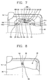
- Fig. 7 schematically illustrates an alternative locking mechanism in accordance with another embodiment of the present invention.
- Fig. 8 schematically illustrates the general exterior of a mobile telephone set in accordance with the embodiment shown in reference to Fig. 7.
- Figs. 9A and 9B schematically depict the locking of a battery cover to the main body of a mobile telephone set utilizing the locking mechanism of Fig. 7.
- Figs. 10A and 10B schematically depict the unlocking of a battery cover from the main body of a mobile telephone set utilizing the locking mechanism of Fig. 7.
- FIG. 4 schematically illustrates a locking mechanism in accordance with a preferred embodiment of the present invention.
- the locking mechanism may be used to securely lock a battery cover to the main body of a mobile telephone set, as generally shown in reference to Fig. 4.
- the battery cover locking mechanism of Fig. 4 preferably comprises a pair of oppositely disposed generally hook-shaped latching members 21 formed on a battery cover 20, and a pair of locking members 50 movably disposed opposite each other within a main body 10 of a mobile telephone set and adapted to engage latching members 21 to secure battery cover 20 to main body 10.
- the battery cover locking mechanism also comprises a pair of knobs 40, each one extending integrally from a corresponding locking member 50 and to which an external force may be applied for moving linearly locking members 50, and a pair of oppositely disposed elastic members 30, each one operatively coupled between a corresponding locking member 50 and a support member 12 which is formed in the middle of a groove 11, as generally shown in Fig. 4.
- Groove 11 is disposed in main body 10 and used to guide the linear movement of locking members 50.
- Support member 12 is used to support elastic members 30.
- Each locking member (50) includes a pair of generally oppositely disposed first and second locking legs 51, 52 adapted to form an insertion space 53 for latching member 21.
- First and second locking legs 51, 52 are preferably adapted to engage a corresponding latching member 21 within its respective insertion space 53 to securely lock battery cover 20 to main body 10.
- an inner surface 51a of first locking leg 51 is adapted to engage a corresponding inner surface 21a of latching member 21 to catch the same within insertion space 53, as generally illustrated in Fig. 4.
- Second locking leg 52 includes an inner surface 52a, which is inclined at a predetermined angle so as to generally match the curvature of a corresponding outer surface 21b of latching member 21.
- second locking leg 52 pushes latching member 21 out of insertion space 53 whereby the width of inclined inner surface 52a is related to the pushing force on latching member 21.
- the bigger the width of inner surface 52a the greater the force with which latching member 21 is being pushed.
- Outer surface 21b of latching member 21 is adapted to allow latching member 21 generally smooth entry into insertion space 53 with outer surface 21b pushing against inner surface 52a of second locking leg 52 when battery cover 20 is being locked to main body 10.
- Each elastic member 30 may be in the form of a spring coupled between a corresponding locking member 50 and support member 12 with the springs disposed opposite each other and each spring being biased toward a corresponding latching member (21).
- a single elastic member 30 may include a spring operatively coupled between locking members 50 and being biased at each end toward a corresponding latching member (21).
- Yet another alternative may include a spring coupled between each locking member 50 and main body 10 with the springs disposed opposite each other and each spring being biased toward a corresponding latching member (21).
- Knobs 40 protrude from locking members 50 to provide gripping surface for the user. The user moves locking members 50 toward/away from each other by way of integral knobs 40, respectively.
- each latching member (21) of battery cover 20 gradually enters its respective insertion space (53), each latching member 21 pushes against a corresponding first locking leg 51 forcing locking members 50 to move linearly closer to each other against the bias of elastic members 30, respectively.
- the process of unlocking battery cover 20 from main telephone body 10 is generally depicted in reference to Figs. 6A - 6B.
- the user grips knobs 40 (not shown) and forces locking members 50 to move linearly closer to each other against the bias of elastic members 30 to allow disengagement of inner surface 21a of latching member 21 from inner surface 51a of first locking leg 51, respectively, on each side.
- inner surface 52a of second locking leg 52 pushes against outer surface 21b of its respective latching member 21 with latching member 21 sliding along inclined inner surface 52a, as generally shown in Figs. 6A - 6B, unlocking battery cover 20 from main body 10.
- FIG. 7 schematically illustrates an alternative locking mechanism in accordance with another preferred embodiment of the present invention.
- the locking mechanism may be used to securely lock a battery cover to the main body of a mobile telephone set, as generally shown in reference to Fig. 7.
- the battery cover locking mechanism of Fig. 7 preferably comprises a pair of oppositely disposed generally hook-shaped latching members 21 formed on battery cover 20, and a pair of locking members 150 movably disposed opposite each other within main telephone body 10 and adapted to engage latching members 21 to secure battery cover 20 to main body 10.
- FIG. 7 also comprises a pair of oppositely disposed elastic members 130, each one operatively coupled between a corresponding locking member 150 and a support member 112 which is formed in the middle of a groove 111, as generally shown in Fig. 7.
- Groove 111 is disposed in main body 10 and used to guide the linear movement of locking members 150.
- Support member 112 is used to support elastic members 130.
- Each locking member (150) includes a pair of generally oppositely disposed first and second locking legs 151, 152 adapted to form an insertion space 153 for latching member 21.
- First and second locking legs 151, 152 are preferably adapted to engage a corresponding latching member 21 within its respective insertion space 153 to securely lock battery cover 20 to main body 10.
- an inner surface 151a of first locking leg 151 is adapted to engage a corresponding inner surface 21a of latching member 21 to catch the same within insertion space 153, as generally illustrated in Fig. 7.
- Second locking leg 152 includes an inner surface 152a, which is inclined at a predetermined angle so as to generally match the curvature of a corresponding outer surface 21b of latching member 21.
- Second locking leg 152 pushes latching member 21 out of insertion space 153.
- Outer surface 21b of latching member 21 is adapted to allow latching member 21 generally smooth entry into insertion space 153 with outer surface 21b pushing against inner surface 152a of second locking leg 152 when battery cover 20 is being locked to main body 10.
- Each elastic member 130 may be in the form of a spring coupled between a corresponding locking member 150 and support member 112 with the springs being disposed opposite each other and each spring being biased toward a corresponding latching member (21).
- a single elastic member 130 in the form of a spring may be used to spring load just one or both locking members 150 in the manner described hereinabove.
- Other spring loading configurations may be utilized provided such other configurations do not depart from the intended purpose of the present invention.
- the battery cover locking mechanism of Fig. 7 further comprises a locking member moving apparatus (LMMA) 200 which may be utilized to move locking members 150 toward/away from each other.
- LMMA 200 includes a connection link 160 integrally extending from one of the locking members (150), a knob 140 protruding from connection link 160, a pair of oppositely disposed rack gears 170 with each rack gear extending from a respective locking member (150), and a pinion gear 180 rotatably disposed in guiding groove 111 and adapted to mesh with rack gears 170.
- Knob 140 is adapted to protrude through an aperture 90 formed in a locking mechanism cover 80, as generally shown in Fig. 8. Knob 140 is adapted for gripping by the user. The user moves connection link 160 linearly via knob 140 to unlock battery cover 20 from main telephone body 10.
- each latching member (21) of battery cover 20 gradually enters its respective insertion space (153), each latching member 21 pushes against a corresponding first locking leg 151 forcing locking members 150 to move linearly closer to each other against the bias of elastic members 130, respectively.
- the process of unlocking battery cover 20 from main telephone body 10 is generally depicted in reference to Figs. 10A - 10B.
- the user moves knob 140 generally to the right of central axis 139 (Fig. 8) which forces locking members 150 to move linearly closer to each other against the bias of elastic members 130 by rack-and-pinion action to allow disengagement of inner surface 21a of latching member 21 from inner surface 151a of first locking leg 151, respectively, on each side.
- Moving knob 140 results in a corresponding linear translation of the locking member having the integral connection link (160) which in turn causes a respective rack-and-pinion translation of the other locking member (150) which is not coupled to knob 140.
Landscapes
- Chemical Kinetics & Catalysis (AREA)
- Electrochemistry (AREA)
- General Chemical & Material Sciences (AREA)
- Chemical & Material Sciences (AREA)
- Engineering & Computer Science (AREA)
- Signal Processing (AREA)
- Life Sciences & Earth Sciences (AREA)
- Computer Hardware Design (AREA)
- Biophysics (AREA)
- Computer Networks & Wireless Communication (AREA)
- Telephone Set Structure (AREA)
- Battery Mounting, Suspending (AREA)
- Casings For Electric Apparatus (AREA)
- Holders For Apparel And Elements Relating To Apparel (AREA)
- Switches With Compound Operations (AREA)
- Pens And Brushes (AREA)
Priority Applications (1)
| Application Number | Priority Date | Filing Date | Title |
|---|---|---|---|
| EP20060006266 EP1681838A3 (fr) | 2003-03-25 | 2004-03-22 | Mécanisme de verrouillage |
Applications Claiming Priority (4)
| Application Number | Priority Date | Filing Date | Title |
|---|---|---|---|
| KR10-2003-0018526A KR100531852B1 (ko) | 2003-03-25 | 2003-03-25 | 배터리 커버 로킹장치 |
| KR2003018528 | 2003-03-25 | ||
| KR10-2003-0018528A KR100504823B1 (ko) | 2003-03-25 | 2003-03-25 | 휴대폰의 배터리 커버 로킹장치 |
| KR2003018526 | 2003-03-25 |
Related Child Applications (1)
| Application Number | Title | Priority Date | Filing Date |
|---|---|---|---|
| EP20060006266 Division EP1681838A3 (fr) | 2003-03-25 | 2004-03-22 | Mécanisme de verrouillage |
Publications (2)
| Publication Number | Publication Date |
|---|---|
| EP1463275A1 true EP1463275A1 (fr) | 2004-09-29 |
| EP1463275B1 EP1463275B1 (fr) | 2008-05-07 |
Family
ID=32829128
Family Applications (2)
| Application Number | Title | Priority Date | Filing Date |
|---|---|---|---|
| EP20060006266 Withdrawn EP1681838A3 (fr) | 2003-03-25 | 2004-03-22 | Mécanisme de verrouillage |
| EP20040006875 Expired - Lifetime EP1463275B1 (fr) | 2003-03-25 | 2004-03-22 | Mécanisme de verrouillage |
Family Applications Before (1)
| Application Number | Title | Priority Date | Filing Date |
|---|---|---|---|
| EP20060006266 Withdrawn EP1681838A3 (fr) | 2003-03-25 | 2004-03-22 | Mécanisme de verrouillage |
Country Status (6)
| Country | Link |
|---|---|
| US (2) | US7197344B2 (fr) |
| EP (2) | EP1681838A3 (fr) |
| JP (1) | JP4048303B2 (fr) |
| CN (1) | CN1284252C (fr) |
| AT (1) | ATE394869T1 (fr) |
| DE (1) | DE602004013482D1 (fr) |
Cited By (5)
| Publication number | Priority date | Publication date | Assignee | Title |
|---|---|---|---|---|
| WO2006014112A1 (fr) * | 2004-08-02 | 2006-02-09 | Tait Electronics Limited | Assemblage de blocage de batterie |
| CN101867025A (zh) * | 2009-04-17 | 2010-10-20 | 鸿富锦精密工业(深圳)有限公司 | 电池盖及采用该电池盖的电子装置 |
| EP1981249A3 (fr) * | 2007-04-11 | 2011-02-02 | Hytera Communications Corp., Ltd. | Structure de verrouillage de batterie |
| US8297666B2 (en) | 2009-03-27 | 2012-10-30 | Research In Motion Limited | Battery cover and latch assembly for a portable electronic device |
| US8556303B2 (en) | 2009-08-19 | 2013-10-15 | Blackberry Limited | Battery cover and pivoting latch assembly for a portable electronic device |
Families Citing this family (18)
| Publication number | Priority date | Publication date | Assignee | Title |
|---|---|---|---|---|
| US20050084747A1 (en) * | 2003-10-17 | 2005-04-21 | Allen Aaron R. | Latching mechanism for electronic device and method of assembly |
| KR20060034353A (ko) * | 2004-10-18 | 2006-04-24 | 삼성전자주식회사 | 배터리팩과 배터리 착탈장치 및 전자기기 |
| KR100689510B1 (ko) * | 2004-12-27 | 2007-03-02 | 삼성전자주식회사 | 휴대용 단말기의 배터리 팩 락킹 장치 |
| JP4581677B2 (ja) * | 2004-12-27 | 2010-11-17 | セイコーエプソン株式会社 | ピーラー機能付きプリンタ |
| US20060175840A1 (en) * | 2005-02-04 | 2006-08-10 | Fih Co., Ltd | Battery cover latching assembly for portable electronic device |
| CN1905573B (zh) * | 2005-07-29 | 2011-06-08 | 深圳富泰宏精密工业有限公司 | 电池盖卡锁结构 |
| US20080036217A1 (en) * | 2006-08-10 | 2008-02-14 | Ching-Hsiang Wang | Double door hook for an oven |
| KR100827113B1 (ko) * | 2006-10-19 | 2008-05-02 | 삼성전자주식회사 | 휴대 단말기의 내장형 배터리팩 커버 락킹 장치 |
| US8013932B2 (en) * | 2008-08-27 | 2011-09-06 | Raymond Chan | Waterproof electronic recording device |
| CN101754613A (zh) * | 2008-12-22 | 2010-06-23 | 深圳富泰宏精密工业有限公司 | 电子装置 |
| CN101887953B (zh) * | 2009-05-15 | 2013-02-20 | 深圳富泰宏精密工业有限公司 | 电池盖卡锁结构及该便携式电子装置 |
| CN101896047B (zh) * | 2009-05-19 | 2013-06-05 | 鸿富锦精密工业(深圳)有限公司 | 电子设备及其卡止装置 |
| TWI421017B (zh) * | 2009-06-19 | 2013-12-21 | Hon Hai Prec Ind Co Ltd | 電子設備及其卡止裝置 |
| CA2708968A1 (fr) * | 2009-07-07 | 2011-01-07 | Research In Motion Corporation | Mecanisme de verrouillage pour couvercle de boitier de dispositif electronique |
| TWI481782B (zh) * | 2010-01-14 | 2015-04-21 | Hon Hai Prec Ind Co Ltd | 電子裝置 |
| CN108735925A (zh) * | 2017-04-20 | 2018-11-02 | 富泰华工业(深圳)有限公司 | 电子装置 |
| CN109698289B (zh) * | 2018-12-26 | 2022-01-07 | 重庆蓝岸通讯技术有限公司 | 一种电池盖锁紧装置和便携电子设备 |
| CN115465071B (zh) * | 2022-09-26 | 2024-06-11 | 阿尔特汽车技术股份有限公司 | 一种连接结构及车辆 |
Citations (4)
| Publication number | Priority date | Publication date | Assignee | Title |
|---|---|---|---|---|
| US5615250A (en) * | 1993-07-23 | 1997-03-25 | Nec Corporation | Portable telephone set for use with IC card |
| US5621618A (en) * | 1995-06-12 | 1997-04-15 | Nec Corporation | Portable electronic apparatus with battery pack secured by first and second sequentially engageable recesses |
| EP0802660A2 (fr) * | 1996-04-18 | 1997-10-22 | VARTA Batterie Aktiengesellschaft | Boîtier de batterie pour téléphones portables |
| US20020160255A1 (en) * | 2001-04-26 | 2002-10-31 | International Business Machines Corporation | Battery latch and method |
Family Cites Families (21)
| Publication number | Priority date | Publication date | Assignee | Title |
|---|---|---|---|---|
| JPS5835827Y2 (ja) | 1978-06-07 | 1983-08-12 | 松下電器産業株式会社 | 電気機器の扉装置 |
| US4239269A (en) * | 1979-01-02 | 1980-12-16 | Chiang Chih Chang | Luggage lock |
| JPH0820919B2 (ja) * | 1989-05-16 | 1996-03-04 | 株式会社東芝 | ハンディターミナル |
| JPH0384181A (ja) | 1989-08-28 | 1991-04-09 | Nippondenso Co Ltd | ドアロック駆動装置 |
| US5028083A (en) * | 1990-04-27 | 1991-07-02 | Motorola, Inc. | Latch assembly |
| JPH0555585A (ja) | 1991-08-29 | 1993-03-05 | Sanyo Electric Co Ltd | 絶縁ゲート形電界効果トランジスタの製造方法 |
| US5202197A (en) * | 1991-10-17 | 1993-04-13 | International Business Machines Corporation | Data processing device having an improved manually operated battery eject mechanism and a warning light |
| JP2686206B2 (ja) | 1992-04-21 | 1997-12-08 | 三洋電機株式会社 | 電子機器 |
| JPH0878862A (ja) | 1994-09-08 | 1996-03-22 | Goyo Denshi Kogyo Kk | 蓋のロック装置 |
| JP2674537B2 (ja) * | 1994-11-30 | 1997-11-12 | 日本電気株式会社 | 電子機器筐体 |
| JP3063819B2 (ja) | 1995-10-31 | 2000-07-12 | 富士通テン株式会社 | 摺動ドアのロック機構 |
| US6073027A (en) * | 1996-08-29 | 2000-06-06 | Bellsouth Corporation | Portable radiotelephone with sliding cover and automatic antenna extension |
| US5848719A (en) * | 1997-05-02 | 1998-12-15 | Motorola, Inc. | Battery cover latch |
| JP3490590B2 (ja) * | 1997-05-29 | 2004-01-26 | 富士通株式会社 | 携帯装置のバッテリロック機構 |
| TW376204U (en) * | 1998-05-12 | 1999-12-01 | Mitac Int Corp | Safety device of slip-proof for the battery case |
| JP3429681B2 (ja) * | 1998-08-06 | 2003-07-22 | 松下電器産業株式会社 | 電池パック取り外し装置 |
| GB9821124D0 (en) * | 1998-09-29 | 1998-11-25 | Nokia Mobile Phones Ltd | Back cover for a mobile phone |
| KR100313145B1 (ko) * | 1998-11-06 | 2001-11-07 | 윤종용 | 와치 타입 휴대용 무선단말기 |
| JP3012642B1 (ja) | 1999-03-12 | 2000-02-28 | 埼玉日本電気株式会社 | バッテリ保持構造と該バッテリ保持構造を備えた携帯型電子機器 |
| US6660427B1 (en) * | 2000-11-06 | 2003-12-09 | Motorola Inc. | Latch assembly for portable electronic device |
| JP2003134209A (ja) * | 2001-10-26 | 2003-05-09 | Toshiba Corp | 無線機器ホルダ |
-
2004
- 2004-03-22 EP EP20060006266 patent/EP1681838A3/fr not_active Withdrawn
- 2004-03-22 EP EP20040006875 patent/EP1463275B1/fr not_active Expired - Lifetime
- 2004-03-22 AT AT04006875T patent/ATE394869T1/de not_active IP Right Cessation
- 2004-03-22 DE DE200460013482 patent/DE602004013482D1/de not_active Expired - Lifetime
- 2004-03-24 US US10/808,776 patent/US7197344B2/en not_active Expired - Fee Related
- 2004-03-25 JP JP2004090584A patent/JP4048303B2/ja not_active Expired - Fee Related
- 2004-03-25 CN CNB2004100315987A patent/CN1284252C/zh not_active Expired - Fee Related
-
2006
- 2006-11-15 US US11/560,095 patent/US7529569B2/en not_active Expired - Fee Related
Patent Citations (4)
| Publication number | Priority date | Publication date | Assignee | Title |
|---|---|---|---|---|
| US5615250A (en) * | 1993-07-23 | 1997-03-25 | Nec Corporation | Portable telephone set for use with IC card |
| US5621618A (en) * | 1995-06-12 | 1997-04-15 | Nec Corporation | Portable electronic apparatus with battery pack secured by first and second sequentially engageable recesses |
| EP0802660A2 (fr) * | 1996-04-18 | 1997-10-22 | VARTA Batterie Aktiengesellschaft | Boîtier de batterie pour téléphones portables |
| US20020160255A1 (en) * | 2001-04-26 | 2002-10-31 | International Business Machines Corporation | Battery latch and method |
Cited By (9)
| Publication number | Priority date | Publication date | Assignee | Title |
|---|---|---|---|---|
| WO2006014112A1 (fr) * | 2004-08-02 | 2006-02-09 | Tait Electronics Limited | Assemblage de blocage de batterie |
| US7758996B2 (en) | 2004-08-02 | 2010-07-20 | Tait Electronics Limited | Battery latching assembly |
| EP1981249A3 (fr) * | 2007-04-11 | 2011-02-02 | Hytera Communications Corp., Ltd. | Structure de verrouillage de batterie |
| US8297666B2 (en) | 2009-03-27 | 2012-10-30 | Research In Motion Limited | Battery cover and latch assembly for a portable electronic device |
| CN101867025A (zh) * | 2009-04-17 | 2010-10-20 | 鸿富锦精密工业(深圳)有限公司 | 电池盖及采用该电池盖的电子装置 |
| US20100266884A1 (en) * | 2009-04-17 | 2010-10-21 | Hong Fu Jin Precision Industry (Shenzhen) Co., Ltd. | Battery cover and electronic device using the same |
| US8329329B2 (en) * | 2009-04-17 | 2012-12-11 | Hong Fu Jin Precision Industry (Shenzhen) Co., Ltd. | Battery cover and electronic device using the same |
| CN101867025B (zh) * | 2009-04-17 | 2013-06-05 | 鸿富锦精密工业(深圳)有限公司 | 电池盖及采用该电池盖的电子装置 |
| US8556303B2 (en) | 2009-08-19 | 2013-10-15 | Blackberry Limited | Battery cover and pivoting latch assembly for a portable electronic device |
Also Published As
| Publication number | Publication date |
|---|---|
| JP2004297068A (ja) | 2004-10-21 |
| JP4048303B2 (ja) | 2008-02-20 |
| US7197344B2 (en) | 2007-03-27 |
| US7529569B2 (en) | 2009-05-05 |
| US20040189011A1 (en) | 2004-09-30 |
| ATE394869T1 (de) | 2008-05-15 |
| CN1532960A (zh) | 2004-09-29 |
| DE602004013482D1 (de) | 2008-06-19 |
| CN1284252C (zh) | 2006-11-08 |
| EP1681838A3 (fr) | 2009-09-16 |
| EP1463275B1 (fr) | 2008-05-07 |
| EP1681838A2 (fr) | 2006-07-19 |
| US20070158961A1 (en) | 2007-07-12 |
Similar Documents
| Publication | Publication Date | Title |
|---|---|---|
| EP1463275A1 (fr) | Mécanisme de verrouillage | |
| US7539521B2 (en) | Locking mechanism | |
| US7892668B2 (en) | Battery locking apparatus for electronic device | |
| AU613546B2 (en) | Battery housing with integral latch and positive displacement apparatus | |
| US5832573A (en) | Quick release buckle assembly | |
| US8744540B2 (en) | Cradle for mobile phones | |
| JP4593111B2 (ja) | ストラップ調節装置を備えた自動係止固定ループ | |
| US9145715B2 (en) | Support device having variable security level | |
| US5307511A (en) | Anti-fall structure for battery cover of radio communication apparatus or similar apparatus | |
| US20180049522A1 (en) | Non-Directional Instant locking fastner | |
| US11554287B2 (en) | Exercise machine connector | |
| US8067860B2 (en) | Electrical device, in particular an electrical hand-held power tool | |
| US6243463B1 (en) | Portable phone cradle having a locking module for a vehicle | |
| US20080142651A1 (en) | Cradle for Mobile Phones and Ejector Device Thereof | |
| EP4210533B1 (fr) | Appareil de liaison | |
| CN1870665B (zh) | 锁定机构 | |
| JP4977381B2 (ja) | 車両用係止装置 | |
| JP2008297725A (ja) | 自動施錠錠前 | |
| JPH10270001A (ja) | 電池パックロック構造 | |
| US8104735B2 (en) | Latching mechanism for holding a removable component in a mount | |
| WO2010057991A1 (fr) | Boucle et ensemble de ceinture de sécurité | |
| JPH0323691A (ja) | 車載無線装置の可搬筐体構造 |
Legal Events
| Date | Code | Title | Description |
|---|---|---|---|
| PUAI | Public reference made under article 153(3) epc to a published international application that has entered the european phase |
Free format text: ORIGINAL CODE: 0009012 |
|
| 17P | Request for examination filed |
Effective date: 20040322 |
|
| AK | Designated contracting states |
Kind code of ref document: A1 Designated state(s): AT BE BG CH CY CZ DE DK EE ES FI FR GB GR HU IE IT LI LU MC NL PL PT RO SE SI SK TR |
|
| AX | Request for extension of the european patent |
Extension state: AL LT LV MK |
|
| AKX | Designation fees paid |
Designated state(s): AT BE BG CH CY CZ DE DK EE ES FI FR GB GR HU IE IT LI LU MC NL PL PT RO SE SI SK TR |
|
| 17Q | First examination report despatched |
Effective date: 20050504 |
|
| GRAP | Despatch of communication of intention to grant a patent |
Free format text: ORIGINAL CODE: EPIDOSNIGR1 |
|
| GRAS | Grant fee paid |
Free format text: ORIGINAL CODE: EPIDOSNIGR3 |
|
| GRAA | (expected) grant |
Free format text: ORIGINAL CODE: 0009210 |
|
| AK | Designated contracting states |
Kind code of ref document: B1 Designated state(s): AT BE BG CH CY CZ DE DK EE ES FI FR GB GR HU IE IT LI LU MC NL PL PT RO SE SI SK TR |
|
| REG | Reference to a national code |
Ref country code: GB Ref legal event code: FG4D |
|
| REG | Reference to a national code |
Ref country code: CH Ref legal event code: EP |
|
| REG | Reference to a national code |
Ref country code: IE Ref legal event code: FG4D Free format text: LANGUAGE OF EP DOCUMENT: FRENCH |
|
| REF | Corresponds to: |
Ref document number: 602004013482 Country of ref document: DE Date of ref document: 20080619 Kind code of ref document: P |
|
| PG25 | Lapsed in a contracting state [announced via postgrant information from national office to epo] |
Ref country code: SI Free format text: LAPSE BECAUSE OF FAILURE TO SUBMIT A TRANSLATION OF THE DESCRIPTION OR TO PAY THE FEE WITHIN THE PRESCRIBED TIME-LIMIT Effective date: 20080507 |
|
| PG25 | Lapsed in a contracting state [announced via postgrant information from national office to epo] |
Ref country code: ES Free format text: LAPSE BECAUSE OF FAILURE TO SUBMIT A TRANSLATION OF THE DESCRIPTION OR TO PAY THE FEE WITHIN THE PRESCRIBED TIME-LIMIT Effective date: 20080818 Ref country code: FI Free format text: LAPSE BECAUSE OF FAILURE TO SUBMIT A TRANSLATION OF THE DESCRIPTION OR TO PAY THE FEE WITHIN THE PRESCRIBED TIME-LIMIT Effective date: 20080507 Ref country code: NL Free format text: LAPSE BECAUSE OF FAILURE TO SUBMIT A TRANSLATION OF THE DESCRIPTION OR TO PAY THE FEE WITHIN THE PRESCRIBED TIME-LIMIT Effective date: 20080507 |
|
| NLV1 | Nl: lapsed or annulled due to failure to fulfill the requirements of art. 29p and 29m of the patents act | ||
| PG25 | Lapsed in a contracting state [announced via postgrant information from national office to epo] |
Ref country code: AT Free format text: LAPSE BECAUSE OF FAILURE TO SUBMIT A TRANSLATION OF THE DESCRIPTION OR TO PAY THE FEE WITHIN THE PRESCRIBED TIME-LIMIT Effective date: 20080507 Ref country code: PL Free format text: LAPSE BECAUSE OF FAILURE TO SUBMIT A TRANSLATION OF THE DESCRIPTION OR TO PAY THE FEE WITHIN THE PRESCRIBED TIME-LIMIT Effective date: 20080507 |
|
| PG25 | Lapsed in a contracting state [announced via postgrant information from national office to epo] |
Ref country code: CZ Free format text: LAPSE BECAUSE OF FAILURE TO SUBMIT A TRANSLATION OF THE DESCRIPTION OR TO PAY THE FEE WITHIN THE PRESCRIBED TIME-LIMIT Effective date: 20080507 Ref country code: SE Free format text: LAPSE BECAUSE OF FAILURE TO SUBMIT A TRANSLATION OF THE DESCRIPTION OR TO PAY THE FEE WITHIN THE PRESCRIBED TIME-LIMIT Effective date: 20080807 Ref country code: PT Free format text: LAPSE BECAUSE OF FAILURE TO SUBMIT A TRANSLATION OF THE DESCRIPTION OR TO PAY THE FEE WITHIN THE PRESCRIBED TIME-LIMIT Effective date: 20081007 Ref country code: DK Free format text: LAPSE BECAUSE OF FAILURE TO SUBMIT A TRANSLATION OF THE DESCRIPTION OR TO PAY THE FEE WITHIN THE PRESCRIBED TIME-LIMIT Effective date: 20080507 |
|
| PG25 | Lapsed in a contracting state [announced via postgrant information from national office to epo] |
Ref country code: RO Free format text: LAPSE BECAUSE OF FAILURE TO SUBMIT A TRANSLATION OF THE DESCRIPTION OR TO PAY THE FEE WITHIN THE PRESCRIBED TIME-LIMIT Effective date: 20080507 Ref country code: SK Free format text: LAPSE BECAUSE OF FAILURE TO SUBMIT A TRANSLATION OF THE DESCRIPTION OR TO PAY THE FEE WITHIN THE PRESCRIBED TIME-LIMIT Effective date: 20080507 Ref country code: BE Free format text: LAPSE BECAUSE OF FAILURE TO SUBMIT A TRANSLATION OF THE DESCRIPTION OR TO PAY THE FEE WITHIN THE PRESCRIBED TIME-LIMIT Effective date: 20080507 |
|
| PLBE | No opposition filed within time limit |
Free format text: ORIGINAL CODE: 0009261 |
|
| STAA | Information on the status of an ep patent application or granted ep patent |
Free format text: STATUS: NO OPPOSITION FILED WITHIN TIME LIMIT |
|
| 26N | No opposition filed |
Effective date: 20090210 |
|
| PG25 | Lapsed in a contracting state [announced via postgrant information from national office to epo] |
Ref country code: EE Free format text: LAPSE BECAUSE OF FAILURE TO SUBMIT A TRANSLATION OF THE DESCRIPTION OR TO PAY THE FEE WITHIN THE PRESCRIBED TIME-LIMIT Effective date: 20080507 Ref country code: BG Free format text: LAPSE BECAUSE OF FAILURE TO SUBMIT A TRANSLATION OF THE DESCRIPTION OR TO PAY THE FEE WITHIN THE PRESCRIBED TIME-LIMIT Effective date: 20080807 |
|
| PG25 | Lapsed in a contracting state [announced via postgrant information from national office to epo] |
Ref country code: MC Free format text: LAPSE BECAUSE OF NON-PAYMENT OF DUE FEES Effective date: 20090331 |
|
| REG | Reference to a national code |
Ref country code: CH Ref legal event code: PL |
|
| PG25 | Lapsed in a contracting state [announced via postgrant information from national office to epo] |
Ref country code: IE Free format text: LAPSE BECAUSE OF NON-PAYMENT OF DUE FEES Effective date: 20090322 Ref country code: LI Free format text: LAPSE BECAUSE OF NON-PAYMENT OF DUE FEES Effective date: 20090331 Ref country code: CH Free format text: LAPSE BECAUSE OF NON-PAYMENT OF DUE FEES Effective date: 20090331 |
|
| PG25 | Lapsed in a contracting state [announced via postgrant information from national office to epo] |
Ref country code: GR Free format text: LAPSE BECAUSE OF FAILURE TO SUBMIT A TRANSLATION OF THE DESCRIPTION OR TO PAY THE FEE WITHIN THE PRESCRIBED TIME-LIMIT Effective date: 20080808 |
|
| PG25 | Lapsed in a contracting state [announced via postgrant information from national office to epo] |
Ref country code: LU Free format text: LAPSE BECAUSE OF NON-PAYMENT OF DUE FEES Effective date: 20090322 |
|
| PG25 | Lapsed in a contracting state [announced via postgrant information from national office to epo] |
Ref country code: HU Free format text: LAPSE BECAUSE OF FAILURE TO SUBMIT A TRANSLATION OF THE DESCRIPTION OR TO PAY THE FEE WITHIN THE PRESCRIBED TIME-LIMIT Effective date: 20081108 |
|
| PG25 | Lapsed in a contracting state [announced via postgrant information from national office to epo] |
Ref country code: TR Free format text: LAPSE BECAUSE OF FAILURE TO SUBMIT A TRANSLATION OF THE DESCRIPTION OR TO PAY THE FEE WITHIN THE PRESCRIBED TIME-LIMIT Effective date: 20080507 |
|
| PG25 | Lapsed in a contracting state [announced via postgrant information from national office to epo] |
Ref country code: CY Free format text: LAPSE BECAUSE OF FAILURE TO SUBMIT A TRANSLATION OF THE DESCRIPTION OR TO PAY THE FEE WITHIN THE PRESCRIBED TIME-LIMIT Effective date: 20080507 |
|
| REG | Reference to a national code |
Ref country code: FR Ref legal event code: PLFP Year of fee payment: 13 |
|
| PGFP | Annual fee paid to national office [announced via postgrant information from national office to epo] |
Ref country code: DE Payment date: 20160212 Year of fee payment: 13 |
|
| PGFP | Annual fee paid to national office [announced via postgrant information from national office to epo] |
Ref country code: GB Payment date: 20160216 Year of fee payment: 13 Ref country code: FR Payment date: 20160217 Year of fee payment: 13 |
|
| PGFP | Annual fee paid to national office [announced via postgrant information from national office to epo] |
Ref country code: IT Payment date: 20160317 Year of fee payment: 13 |
|
| REG | Reference to a national code |
Ref country code: DE Ref legal event code: R119 Ref document number: 602004013482 Country of ref document: DE |
|
| GBPC | Gb: european patent ceased through non-payment of renewal fee |
Effective date: 20170322 |
|
| REG | Reference to a national code |
Ref country code: FR Ref legal event code: ST Effective date: 20171130 |
|
| PG25 | Lapsed in a contracting state [announced via postgrant information from national office to epo] |
Ref country code: FR Free format text: LAPSE BECAUSE OF NON-PAYMENT OF DUE FEES Effective date: 20170331 Ref country code: DE Free format text: LAPSE BECAUSE OF NON-PAYMENT OF DUE FEES Effective date: 20171003 |
|
| PG25 | Lapsed in a contracting state [announced via postgrant information from national office to epo] |
Ref country code: GB Free format text: LAPSE BECAUSE OF NON-PAYMENT OF DUE FEES Effective date: 20170322 Ref country code: IT Free format text: LAPSE BECAUSE OF NON-PAYMENT OF DUE FEES Effective date: 20170322 |