EP1463377A2 - Verfahren zur Lautsprecherherstellung durch Ultraschallvibrationsschweissen und nach diesem Verfahren hergestellte Lautsprecher - Google Patents
Verfahren zur Lautsprecherherstellung durch Ultraschallvibrationsschweissen und nach diesem Verfahren hergestellte Lautsprecher Download PDFInfo
- Publication number
- EP1463377A2 EP1463377A2 EP04251691A EP04251691A EP1463377A2 EP 1463377 A2 EP1463377 A2 EP 1463377A2 EP 04251691 A EP04251691 A EP 04251691A EP 04251691 A EP04251691 A EP 04251691A EP 1463377 A2 EP1463377 A2 EP 1463377A2
- Authority
- EP
- European Patent Office
- Prior art keywords
- speaker
- fixed
- frame
- manufacturing
- bobbin
- Prior art date
- Legal status (The legal status is an assumption and is not a legal conclusion. Google has not performed a legal analysis and makes no representation as to the accuracy of the status listed.)
- Granted
Links
Images
Classifications
-
- H—ELECTRICITY
- H04—ELECTRIC COMMUNICATION TECHNIQUE
- H04R—LOUDSPEAKERS, MICROPHONES, GRAMOPHONE PICK-UPS OR LIKE ACOUSTIC ELECTROMECHANICAL TRANSDUCERS; ELECTRIC HEARING AIDS; PUBLIC ADDRESS SYSTEMS
- H04R31/00—Apparatus or processes specially adapted for the manufacture of transducers or diaphragms therefor
- H04R31/006—Interconnection of transducer parts
-
- H—ELECTRICITY
- H04—ELECTRIC COMMUNICATION TECHNIQUE
- H04R—LOUDSPEAKERS, MICROPHONES, GRAMOPHONE PICK-UPS OR LIKE ACOUSTIC ELECTROMECHANICAL TRANSDUCERS; ELECTRIC HEARING AIDS; PUBLIC ADDRESS SYSTEMS
- H04R9/00—Transducers of moving-coil, moving-strip, or moving-wire type
- H04R9/06—Loudspeakers
-
- H—ELECTRICITY
- H04—ELECTRIC COMMUNICATION TECHNIQUE
- H04R—LOUDSPEAKERS, MICROPHONES, GRAMOPHONE PICK-UPS OR LIKE ACOUSTIC ELECTROMECHANICAL TRANSDUCERS; ELECTRIC HEARING AIDS; PUBLIC ADDRESS SYSTEMS
- H04R2209/00—Details of transducers of the moving-coil, moving-strip, or moving-wire type covered by H04R9/00 but not provided for in any of its subgroups
- H04R2209/024—Manufacturing aspects of the magnetic circuit of loudspeaker or microphone transducers
-
- Y—GENERAL TAGGING OF NEW TECHNOLOGICAL DEVELOPMENTS; GENERAL TAGGING OF CROSS-SECTIONAL TECHNOLOGIES SPANNING OVER SEVERAL SECTIONS OF THE IPC; TECHNICAL SUBJECTS COVERED BY FORMER USPC CROSS-REFERENCE ART COLLECTIONS [XRACs] AND DIGESTS
- Y10—TECHNICAL SUBJECTS COVERED BY FORMER USPC
- Y10T—TECHNICAL SUBJECTS COVERED BY FORMER US CLASSIFICATION
- Y10T29/00—Metal working
- Y10T29/49—Method of mechanical manufacture
- Y10T29/49002—Electrical device making
- Y10T29/49005—Acoustic transducer
-
- Y—GENERAL TAGGING OF NEW TECHNOLOGICAL DEVELOPMENTS; GENERAL TAGGING OF CROSS-SECTIONAL TECHNOLOGIES SPANNING OVER SEVERAL SECTIONS OF THE IPC; TECHNICAL SUBJECTS COVERED BY FORMER USPC CROSS-REFERENCE ART COLLECTIONS [XRACs] AND DIGESTS
- Y10—TECHNICAL SUBJECTS COVERED BY FORMER USPC
- Y10T—TECHNICAL SUBJECTS COVERED BY FORMER US CLASSIFICATION
- Y10T29/00—Metal working
- Y10T29/49—Method of mechanical manufacture
- Y10T29/49002—Electrical device making
- Y10T29/4902—Electromagnet, transformer or inductor
- Y10T29/4908—Acoustic transducer
-
- Y—GENERAL TAGGING OF NEW TECHNOLOGICAL DEVELOPMENTS; GENERAL TAGGING OF CROSS-SECTIONAL TECHNOLOGIES SPANNING OVER SEVERAL SECTIONS OF THE IPC; TECHNICAL SUBJECTS COVERED BY FORMER USPC CROSS-REFERENCE ART COLLECTIONS [XRACs] AND DIGESTS
- Y10—TECHNICAL SUBJECTS COVERED BY FORMER USPC
- Y10T—TECHNICAL SUBJECTS COVERED BY FORMER US CLASSIFICATION
- Y10T29/00—Metal working
- Y10T29/49—Method of mechanical manufacture
- Y10T29/49718—Repairing
- Y10T29/49721—Repairing with disassembling
- Y10T29/49723—Repairing with disassembling including reconditioning of part
- Y10T29/49725—Repairing with disassembling including reconditioning of part by shaping
- Y10T29/49726—Removing material
- Y10T29/49728—Removing material and by a metallurgical operation, e.g., welding, diffusion bonding, casting
Definitions
- the present invention relates to a manufacturing method for a speaker for use in various audio equipment, and more specifically to a manufacturing method, in which main components of a speaker are fixed by ultrasonic complex vibration welding, and also to a speaker produced by such a manufacturing method.
- constituent parts of a magnetic circuit are fixed to each other by means of adhesive
- a frame is fixed to the magnetic circuit by means of screwing or crimping
- a diaphragm is fixed to a surround by means of adhesive
- the surround is fixed to the frame by means of adhesive.
- Adhesive itself is very troublesome to manage, and fixation by adhesive raises various problems with respect to productivity and cost, such as variation in adhering process, difficulty in reducing curing time, and the like.
- a manufacturing method of a speaker is disclosed in, for example, Japanese Patent Application Laid-Open No. S57-13897.
- a surround is fixed to a frame by ultrasonic welding.
- a spider is formed of a hot-cold processed woven fabric which is made of core-in-sheath type filaments, each comprising a core of polyethylene terephthalate and a sheathing of polypropylene, and in which the intersecting portions of the filaments are firmly connected to each other due to the sheathing material heat-fused by the hot-cold process, and the spider thus formed is fixed by ultrasonic welding to a frame formed of resin.
- the spider thus structured can be produced at a lower temperature than conventionally, no special cooling system is required, and therefore existing equipments can be used as they are. And the spider structured and produced as described above is excellent in vital properties required, such as flexibility, chemical resistance, and adhesiveness.
- the material of the frame is required to be excellent in weldability with the surround so that the frame and the surround are duly fixed to each other by ultrasonic welding.
- the spider and the frame are fixed to each other by means of ultrasonic welding without using adhesive, there is no disclosure or even suggestion of the spider and frame being of materials which enable the spider and the frame to be duly ultrasonic-welded to each other, and also no such products as disclosed have been put to practical use.
- the present invention has been made in light of the above circumstances, and it is an object of the present invention to provide a manufacturing method for a speaker, where a speaker can be produced by using a minimum amount of environmentally-unfriendly adhesive, at an ambient temperature, and at a drastically reduced cost, and to provide also a speaker which is produced in according with such a manufacturing method and which has an excellent quality.
- ultrasonic complex vibration welding is implemented in a manufacturing method for a speaker which comprises: a magnetic circuit including a magnet, pot yoke and a pole piece; a frame; a spider; a bobbin having a voice coil wound therearound; a diaphragm; a surround; terminals; and tinsel leads interconnecting the voice coil and the terminals.
- the ultrasonic complex vibration welding is applied to the following processes:
- the ultrasonic complex vibration welding may be implemented such that respective opposing inward surfaces of two components to be fixed together are brought into contact with each other and are positioned relative to each other, and then that ultrasonic vibrations oriented in different directions are simultaneously provided to the inward surfaces while a load is applied to one of the outward surfaces defined by the two components in a direction vertical to the inward surfaces.
- a speaker is produced by the manufacturing method in accordance with the first aspect.
- the assembly and production is accomplished under a clean circumstance at an ambient temperature, therefore eliminating thermal influence, and in good condition, whereby the productivity is significantly enhanced while maintaining a consistent and good quality. Also, since the ultrasonic complex vibration welding achieves a firm connection without thermal influence, the components welded do not suffer degradation thus providing a reliable product with a good quality.
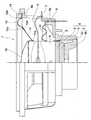
- a speaker 1 generally comprises: a magnetic circuit 5 including a pot yoke 2 consisting of a cylindrical wall section 2a and a base section 2b, a magnet 3, and pole piece 4; a frame 6 formed of resin and attached at an upper opening portion of the pot yoke 2; terminals 7 secured to an outer circumference of the frame 6; a tubular bobbin 9 having a voice coil 8 wound therearound; a spider 10 formed of resin-impregnated fabric, having its inner periphery fixedly connected to a middle portion of an outer circumference of the bobbin 9, and having its outer periphery fixedly attached to a spider attachment region 6a formed at a portion of an inner circumference of the frame 6; a diaphragm 11 having an inner periphery 11a thereof fixedly connected to a top portion of the outer circumference of the bobbin 9; a surround 12 formed of resin, having an inner circumferential edge 12a thereof fixed to an outer periphery 11b of the diaphrag
- the magnet 3 is made either of cast metal, such as alnico, iron chrome, and the like, or of plated metal, such as neodymium.
- the speaker 1 further includes a gasket 14 sitting fixedly on an upper side of the outer circumferential edge 12b of the surround 12, and a dust cap 15 to cover up a top opening of the bobbin 9.
- the speaker 1 structured as described above is assembled by a manufacturing method described below.
- the magnet 3 and the pole piece 4 are welded together by ultrasonic complex vibration, and the magnet 3 and the pot yoke 2 are welded together by ultrasonic complex vibration via aluminum foil (not shown) interposed therebetween.
- the magnet 3 and the pot yoke 2 can practically be welded together directly without aluminum foil therebetween, though the welding strength decreases a little.
- the magnet circuit 5 shown in Fig. 1 is an inner magnet type, but may alternatively be an outer magnet type.
- Both terminations of the voice coil 8 are weldedly connected to respective one ends of the tinsel leads 13 by ultrasonic complex vibration, and the welded connections are adhesively fixed to the bobbin 9.
- the bobbin 9 with the voice coil 8 thus processed is placed inside the magnetic circuit 5 by using a jig so that the voice coil 8 is positioned between the pole piece 4 and the cylindrical wall section 2a of the pot yoke 2.
- the bobbin 9 should preferably have its outer circumference fixedly connected to the inner periphery of the spider 10 beforehand, in which case the outer periphery of the spider 10 is fixed to the spider attachment portion 6a of the frame 6 by ultrasonic complex vibration while the bobbin 9 is held in place by the jig as described above.
- the other ends of the tinsel leads 13 are weldedly connected to the terminals 7 by ultrasonic complex vibration, the gasket 14 is adhesively attached to the upper side of the outer circumference edge 12b of the surround 12, and the dust cap 15 is placed so as to cover up the top opening of the bobbin 9.
- the speaker 1 is completed.
- the welding work by ultrasonic complex vibration may be implemented in several ways. For example, when welding the magnet 3 and the pole piece 4, the magnet 3 is first placed on an anvil, the pole piece 4 is then put on the magnet 3 and appropriately positioned, a welding head (not shown) is applied onto the pole piece 4, a pair of Langevin type transducers (not shown) are driven with an appropriate amount of load applied thereby causing ultrasonic complex vibration at the welding head, the ultrasonic complex vibration caused is transferred via a horn (not shown) to contact surfaces of the magnet 3 and the pole piece 4, and the welding head and the contact surfaces are moved relative to each other in different directions for fusing the contact surfaces entirely.
- a welding head not shown
- the magnet 3 and pole piece 4 can be connected to each other in a very short time without undergoing thermal shock, and in good condition. Contaminants on the welding surface of the magnet 3 or the pole piece 4, if any, are dissipated by ultrasonic vibration, thus enabling a reliable and uniform welding with less energy.
Landscapes
- Engineering & Computer Science (AREA)
- Physics & Mathematics (AREA)
- Acoustics & Sound (AREA)
- Signal Processing (AREA)
- Manufacturing & Machinery (AREA)
- Audible-Bandwidth Dynamoelectric Transducers Other Than Pickups (AREA)
- Diaphragms For Electromechanical Transducers (AREA)
Applications Claiming Priority (2)
| Application Number | Priority Date | Filing Date | Title |
|---|---|---|---|
| JP2003087406 | 2003-03-27 | ||
| JP2003087406A JP2004297467A (ja) | 2003-03-27 | 2003-03-27 | スピーカの製造法及びスピーカ |
Publications (3)
| Publication Number | Publication Date |
|---|---|
| EP1463377A2 true EP1463377A2 (de) | 2004-09-29 |
| EP1463377A3 EP1463377A3 (de) | 2006-04-05 |
| EP1463377B1 EP1463377B1 (de) | 2007-01-24 |
Family
ID=32821538
Family Applications (1)
| Application Number | Title | Priority Date | Filing Date |
|---|---|---|---|
| EP04251691A Expired - Lifetime EP1463377B1 (de) | 2003-03-27 | 2004-03-24 | Verfahren zur Lautsprecherherstellung durch Ultraschallvibrationsschweissen und nach diesem Verfahren hergestellter Lautsprecher |
Country Status (4)
| Country | Link |
|---|---|
| US (1) | US7246425B2 (de) |
| EP (1) | EP1463377B1 (de) |
| JP (1) | JP2004297467A (de) |
| DE (1) | DE602004004425T2 (de) |
Cited By (1)
| Publication number | Priority date | Publication date | Assignee | Title |
|---|---|---|---|---|
| CZ306472B6 (cs) * | 2009-08-07 | 2017-02-08 | Varroc Lighting Systems, s.r.o. | Způsob zpracování výrobku k umožnění jeho sestavení s tělesem hlavní skupiny |
Families Citing this family (5)
| Publication number | Priority date | Publication date | Assignee | Title |
|---|---|---|---|---|
| JP4867774B2 (ja) * | 2007-04-26 | 2012-02-01 | パナソニック株式会社 | スピーカ |
| TWI419577B (zh) * | 2009-12-23 | 2013-12-11 | Ind Tech Res Inst | 揚聲器的製造方法與裝置 |
| CN107770715B (zh) * | 2017-09-20 | 2020-02-11 | 重庆工商大学 | 一种挂式耳机底壳部件的全自动组装机 |
| WO2021128043A1 (zh) * | 2019-12-25 | 2021-07-01 | 瑞声声学科技(深圳)有限公司 | 一种双面发声扬声器 |
| CN113727256B (zh) * | 2020-05-25 | 2022-09-20 | 歌尔股份有限公司 | 发声装置及电子设备 |
Family Cites Families (15)
| Publication number | Priority date | Publication date | Assignee | Title |
|---|---|---|---|---|
| AT338351B (de) * | 1975-04-29 | 1977-08-25 | Philips Nv | Elektroakustischer wandler, verfahren zur herstellung eines solchen wandlers und vorrichtung zur durchfuhrung solcher verfahren |
| JPS5713897A (en) | 1980-06-28 | 1982-01-23 | Citizen Watch Co Ltd | Structure of speaker |
| FR2542551A1 (fr) | 1983-03-07 | 1984-09-14 | Picart Lebas | Traducteur electroacoustique de type dynamique, notamment pour appareils |
| JPS59178099A (ja) | 1983-03-28 | 1984-10-09 | Onkyo Corp | ボイスコイルのリ−ド線取付法 |
| US4566178A (en) * | 1984-12-28 | 1986-01-28 | Phase Technology Corporation | Process for assembling a cone speaker |
| US4825533A (en) * | 1985-10-11 | 1989-05-02 | Pioneer Electronic Corporation | Method of making a voice coil with rectangular coil wire and foil leads |
| EP0251057A1 (de) | 1986-06-21 | 1988-01-07 | EWD Electronic-Werke Deutschland GmbH | Lautsprecher |
| JPH04278552A (ja) | 1991-03-07 | 1992-10-05 | Ricoh Co Ltd | 超音波ワイヤボンディング方法 |
| JPH06335088A (ja) | 1993-05-25 | 1994-12-02 | Minebea Co Ltd | スピーカの製造方法 |
| JPH11122696A (ja) | 1997-10-15 | 1999-04-30 | Foster Electric Co Ltd | スピーカ用ダンパーおよびこのダンパーを用いたスピーカ |
| JP3398337B2 (ja) | 1999-03-24 | 2003-04-21 | 株式会社アサヒ・イー・エム・エス | 超音波複合振動を用いた熱交換器構成部材の接合方法 |
| AT412602B (de) | 1999-09-23 | 2005-04-25 | Akg Acoustics Gmbh | Elektroakustischer wandler nach dem elektrodynamischen prinzip |
| JP2001245387A (ja) | 2000-03-01 | 2001-09-07 | Fujitsu Ten Ltd | スピーカ |
| JP2003066301A (ja) * | 2001-08-29 | 2003-03-05 | Mitsumi Electric Co Ltd | レンズとレンズホルダの接合構造及び接合方法 |
| JP3600983B2 (ja) * | 2002-02-15 | 2004-12-15 | ミネベア株式会社 | スピーカ |
-
2003
- 2003-03-27 JP JP2003087406A patent/JP2004297467A/ja active Pending
-
2004
- 2004-03-17 US US10/801,604 patent/US7246425B2/en not_active Expired - Fee Related
- 2004-03-24 DE DE602004004425T patent/DE602004004425T2/de not_active Expired - Fee Related
- 2004-03-24 EP EP04251691A patent/EP1463377B1/de not_active Expired - Lifetime
Cited By (1)
| Publication number | Priority date | Publication date | Assignee | Title |
|---|---|---|---|---|
| CZ306472B6 (cs) * | 2009-08-07 | 2017-02-08 | Varroc Lighting Systems, s.r.o. | Způsob zpracování výrobku k umožnění jeho sestavení s tělesem hlavní skupiny |
Also Published As
| Publication number | Publication date |
|---|---|
| EP1463377A3 (de) | 2006-04-05 |
| US7246425B2 (en) | 2007-07-24 |
| DE602004004425D1 (de) | 2007-03-15 |
| EP1463377B1 (de) | 2007-01-24 |
| DE602004004425T2 (de) | 2007-10-31 |
| US20040190748A1 (en) | 2004-09-30 |
| JP2004297467A (ja) | 2004-10-21 |
Similar Documents
| Publication | Publication Date | Title |
|---|---|---|
| JP4764162B2 (ja) | スピーカ装置 | |
| US11076247B2 (en) | Acoustic receiver with b-stage seal and method of making same | |
| JP2002209295A (ja) | マイクロスピーカー | |
| US7221773B2 (en) | Oval speaker apparatus and method of manufacturing the same | |
| US6330340B1 (en) | Loudspeaker with a diaphragm having integral vent bores | |
| EP2725820B1 (de) | Vibrationsmodul für Schallwandler | |
| EP1463377B1 (de) | Verfahren zur Lautsprecherherstellung durch Ultraschallvibrationsschweissen und nach diesem Verfahren hergestellter Lautsprecher | |
| JP3619736B2 (ja) | スピーカ | |
| EP1235462A1 (de) | Lautsprechervorrichtung sowie verfahren und gerät für dessen herstellung | |
| CN110337053A (zh) | 一种超薄喇叭 | |
| US7570776B2 (en) | Speaker device and method of manufacturing the speaker device | |
| CN1120793A (zh) | 电声变换器的制造方法 | |
| US11218812B2 (en) | Speaker device | |
| EP1128705A2 (de) | Lautsprecher | |
| JP3052444B2 (ja) | スピーカおよびその製造方法 | |
| US20050281430A1 (en) | Speaker device | |
| JP3155976B2 (ja) | コ−ン型スピ−カ−及びその製造のために用いる治具 | |
| JP4573547B2 (ja) | スピーカ装置及びその製造方法 | |
| US11665478B2 (en) | Acoustic diaphragm, method of manufacturing acoustic diaphragm, and electroacoustic transducer | |
| JP4610229B2 (ja) | スピーカおよびスピーカの製造方法 | |
| JPH06335088A (ja) | スピーカの製造方法 | |
| JPH04335798A (ja) | スピーカの製造方法 | |
| JP2003070094A (ja) | スピーカ | |
| KR19990031638A (ko) | 진동계 일체형 다이나믹 스피커 및 그 제조방법 | |
| KR20050056011A (ko) | 전기-음향변환장치의 진동체 제조방법 |
Legal Events
| Date | Code | Title | Description |
|---|---|---|---|
| PUAI | Public reference made under article 153(3) epc to a published international application that has entered the european phase |
Free format text: ORIGINAL CODE: 0009012 |
|
| AK | Designated contracting states |
Kind code of ref document: A2 Designated state(s): AT BE BG CH CY CZ DE DK EE ES FI FR GB GR HU IE IT LI LU MC NL PL PT RO SE SI SK TR |
|
| AX | Request for extension of the european patent |
Extension state: AL LT LV MK |
|
| PUAL | Search report despatched |
Free format text: ORIGINAL CODE: 0009013 |
|
| AK | Designated contracting states |
Kind code of ref document: A3 Designated state(s): AT BE BG CH CY CZ DE DK EE ES FI FR GB GR HU IE IT LI LU MC NL PL PT RO SE SI SK TR |
|
| AX | Request for extension of the european patent |
Extension state: AL LT LV MK |
|
| 17P | Request for examination filed |
Effective date: 20060525 |
|
| GRAP | Despatch of communication of intention to grant a patent |
Free format text: ORIGINAL CODE: EPIDOSNIGR1 |
|
| AKX | Designation fees paid |
Designated state(s): DE GB |
|
| GRAS | Grant fee paid |
Free format text: ORIGINAL CODE: EPIDOSNIGR3 |
|
| GRAA | (expected) grant |
Free format text: ORIGINAL CODE: 0009210 |
|
| AK | Designated contracting states |
Kind code of ref document: B1 Designated state(s): DE GB |
|
| REG | Reference to a national code |
Ref country code: GB Ref legal event code: FG4D |
|
| REF | Corresponds to: |
Ref document number: 602004004425 Country of ref document: DE Date of ref document: 20070315 Kind code of ref document: P |
|
| PLBE | No opposition filed within time limit |
Free format text: ORIGINAL CODE: 0009261 |
|
| STAA | Information on the status of an ep patent application or granted ep patent |
Free format text: STATUS: NO OPPOSITION FILED WITHIN TIME LIMIT |
|
| 26N | No opposition filed |
Effective date: 20071025 |
|
| PGFP | Annual fee paid to national office [announced via postgrant information from national office to epo] |
Ref country code: GB Payment date: 20090318 Year of fee payment: 6 |
|
| PGFP | Annual fee paid to national office [announced via postgrant information from national office to epo] |
Ref country code: DE Payment date: 20090319 Year of fee payment: 6 |
|
| GBPC | Gb: european patent ceased through non-payment of renewal fee |
Effective date: 20100324 |
|
| PG25 | Lapsed in a contracting state [announced via postgrant information from national office to epo] |
Ref country code: DE Free format text: LAPSE BECAUSE OF NON-PAYMENT OF DUE FEES Effective date: 20101001 |
|
| PG25 | Lapsed in a contracting state [announced via postgrant information from national office to epo] |
Ref country code: GB Free format text: LAPSE BECAUSE OF NON-PAYMENT OF DUE FEES Effective date: 20100324 |