EP1464265A2 - Staubsauger - Google Patents
Staubsauger Download PDFInfo
- Publication number
- EP1464265A2 EP1464265A2 EP04251834A EP04251834A EP1464265A2 EP 1464265 A2 EP1464265 A2 EP 1464265A2 EP 04251834 A EP04251834 A EP 04251834A EP 04251834 A EP04251834 A EP 04251834A EP 1464265 A2 EP1464265 A2 EP 1464265A2
- Authority
- EP
- European Patent Office
- Prior art keywords
- filter
- separation unit
- cleaner
- vacuum cleaner
- unit
- Prior art date
- Legal status (The legal status is an assumption and is not a legal conclusion. Google has not performed a legal analysis and makes no representation as to the accuracy of the status listed.)
- Granted
Links
- 238000000926 separation method Methods 0.000 claims abstract description 35
- 239000000428 dust Substances 0.000 claims abstract description 14
- 238000012423 maintenance Methods 0.000 abstract description 6
- 238000001914 filtration Methods 0.000 abstract description 2
- 238000004140 cleaning Methods 0.000 description 13
- 230000000717 retained effect Effects 0.000 description 3
- 239000002657 fibrous material Substances 0.000 description 1
- 238000007689 inspection Methods 0.000 description 1
- 238000009877 rendering Methods 0.000 description 1
- 230000002459 sustained effect Effects 0.000 description 1
- 210000001364 upper extremity Anatomy 0.000 description 1
- 238000005406 washing Methods 0.000 description 1
- XLYOFNOQVPJJNP-UHFFFAOYSA-N water Substances O XLYOFNOQVPJJNP-UHFFFAOYSA-N 0.000 description 1
Images

Classifications
-
- A—HUMAN NECESSITIES
- A47—FURNITURE; DOMESTIC ARTICLES OR APPLIANCES; COFFEE MILLS; SPICE MILLS; SUCTION CLEANERS IN GENERAL
- A47L—DOMESTIC WASHING OR CLEANING; SUCTION CLEANERS IN GENERAL
- A47L9/00—Details or accessories of suction cleaners, e.g. mechanical means for controlling the suction or for effecting pulsating action; Storing devices specially adapted to suction cleaners or parts thereof; Carrying-vehicles specially adapted for suction cleaners
- A47L9/10—Filters; Dust separators; Dust removal; Automatic exchange of filters
- A47L9/16—Arrangement or disposition of cyclones or other devices with centrifugal action
- A47L9/1658—Construction of outlets
- A47L9/1666—Construction of outlets with filtering means
-
- A—HUMAN NECESSITIES
- A47—FURNITURE; DOMESTIC ARTICLES OR APPLIANCES; COFFEE MILLS; SPICE MILLS; SUCTION CLEANERS IN GENERAL
- A47L—DOMESTIC WASHING OR CLEANING; SUCTION CLEANERS IN GENERAL
- A47L9/00—Details or accessories of suction cleaners, e.g. mechanical means for controlling the suction or for effecting pulsating action; Storing devices specially adapted to suction cleaners or parts thereof; Carrying-vehicles specially adapted for suction cleaners
- A47L9/20—Means for cleaning filters
-
- Y—GENERAL TAGGING OF NEW TECHNOLOGICAL DEVELOPMENTS; GENERAL TAGGING OF CROSS-SECTIONAL TECHNOLOGIES SPANNING OVER SEVERAL SECTIONS OF THE IPC; TECHNICAL SUBJECTS COVERED BY FORMER USPC CROSS-REFERENCE ART COLLECTIONS [XRACs] AND DIGESTS
- Y10—TECHNICAL SUBJECTS COVERED BY FORMER USPC
- Y10S—TECHNICAL SUBJECTS COVERED BY FORMER USPC CROSS-REFERENCE ART COLLECTIONS [XRACs] AND DIGESTS
- Y10S55/00—Gas separation
- Y10S55/03—Vacuum cleaner
Definitions
- This invention relates to a vacuum cleaner
- vacuum cleaners have comprised a permeable filter bag for separating entrained dirt and dust from the suction airflow and for collecting the separated dirt and dust.
- many vacuum cleaners nowadays comprise a cyclonic separator, which separates entrained dirt and dust from the suction airflow and deposits it in a receptacle for emptying.
- cyclonic separators do not always offer the level of filtration efficiency that is achieved with filter bags.
- it is commonplace to mount a filter downstream of the cyclone separator. In this manner, virtually all dust and dirt is removed from the suction airflow before the air enters the fan of the vacuum cleaner, with the majority of dirt and dust, including all coarse and fibrous material, being retained in the cyclone separator, and the remaining fine dust being retained on the filter.
- European Patent Application No. 1 195 125 discloses an upright vacuum cleaner having a cyclonic separator and a filter mounted downstream of the cyclonic separator.
- the filter is located in a chamber directly above the cyclone chamber and is only accessible once the detachable cylindrical dirt-collection bin is removed from the cleaner.
- the user In order to remove the filter, the user must reach inside the cleaner to release the perforated cyclone air outlet screen, which is retained by a conventional bayonet fixing, and withdraw the filter from its chamber. The filter may then be washed, dried, and returned to the cleaner.
- a disadvantage of the above-mentioned arrangement is that the filter is mounted out of sight and thus there is a tendency for the user to forget to clean the filter regularly. Also, because the filter is mounted out of sight, there is a risk that the cleaner could be used without the filter: it will be appreciated that this will affect the performance and reliability of the cleaner.
- Another disadvantage of the above-mentioned arrangement is that the filter is awkward to remove and the removal involves handling the filter, which is often coated in dirt and dust.
- a vacuum cleaner comprising a body, fan means within the body for creating an airflow through the cleaner and a separation unit mounted to the body for separating dirt and dust from the airflow, the separation unit comprising a cyclone separator and a filter, the filter being removable from the separation unit when the latter is mounted to the body of the cleaner.
- the filter is an integral part of the separator unit, yet can be removed from the cleaner for maintenance, without the entire separator unit having to be disengaged from the body beforehand.
- the separation unit is detachably mounted to the body so that the entire separator unit, with the filter unit in position, may be dismounted as a unit from the cleaner if required, and carried to a disposal point for emptying. Further, because the filter is mounted in the separator unit, it is not enclosed in the body of the vacuum cleaner and is therefore easily accessible for cleaning.
- the filter is mounted to a removable portion of the separation unit, which portion can be removed when the unit is mounted to the body of the cleaner.
- the filter element can be removed and cleaned by holding the removable portion of the separation unit, thereby avoiding handling of the filter by the user and rendering the task of filter cleaning more hygienic and convenient for the user.
- an advantage of mounting the filter to a removable portion of the separation unit is that it enables the filter to be held under a running tap for cleaning without the user getting wet or dirty hands.
- the cleaning power and efficiency of a vacuum cleaner in accordance with this invention are more likely to be maintained than known cleaners with filters, since the prominent positioning and the ease of accessibility of the filter makes filter cleaning and maintenance less likely to be neglected or overlooked.
- the separation unit is generally cylindrical, the filter being mounted to a removable end wall of the separation unit.
- the filter is an annular filter which is mounted concentrically within the cylindrical separation unit.
- the removable end wall of the separation unit comprises a projection which engages the filter.
- the separation unit is mounted to the body of the cleaner such that said end wall is exposed and can be removed axially of the separation unit.
- the cleaner is an upright cleaner, the body of the cleaner comprising a floor-engaging portion and an upstanding portion connected to the floor-engaging portion for partial rotation forwardly and rearwardly about a transverse pivotal axis, the separation unit being mounted to the front of the upstanding portion, such that said end wall faces upwardly in front of the upstanding portion.
- the removable end wall of the separation unit is accessible to the user at the upper extremity of the separator for maintenance of the filter, without the user having to bend down, crouch or adopt another awkward position.
- a handle is provided on the removable portion of the separation unit to which the filter is mounted, in order to enable filter cleaning to be carried out without direct manual handling of the filter by the user.
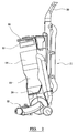
- an upright vacuum cleaner comprising a body having an upright upper portion 11 pivotally connected at its lower end to a floor-engaging portion 12 for partial rotation forwardly and rearwardly about a transverse axis.
- the upper portion 11 of the body encloses a motor/fan unit and comprises a handle 20 at its upper end for pushing the cleaner to and fro.
- the floor-engaging portion 12 of the body incorporates a suction inlet and a conventional motor-driven rotating brush mounted across the inlet.
- a cylindrical separation unit 10 is mounted in an upright configuration to the front of the upper portion 11 of the cleaner, with its longitudinal axis being inclined forwardly and outwardly from its lower end relative to the longitudinal axis of the upper portion 11, such that the upper end wall of the unit 10 is positioned in front of the upper portion 11 of the cleaner.
- the cylindrical separation unit 10 comprises a cyclone separator 13 at its lower end for removing a large proportion of the dirt and dust that is entrained in the airflow.
- the air leaving the separator flows axially upwardly.
- a flap 21 closes the bottom end of the unit 10 and an actuator (not shown) is provided on the rear of the unit for opening the flap 21 to allow the separated dirt and dust to be emptied from the unit, once the latter has been detached from the body of the cleaner.
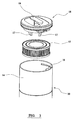
- the air leaving the cyclone separator 13 flows axially upwardly into a chamber 14 at the upper end of the unit 10.
- An annular pleated filter 15 is mounted concentricity inside the chamber 14 and the air leaving the cyclone separator 13 flows upwardly into the centre of the filter 15 and then radially outwardly through the filter 15 before leaving the unit 10 through an outlet 16.
- the filter 15 is mounted on a plurality of splines 17, which project into the annulus of the filter 15.
- the closure 18 comprises a handle 19, which can be used to turn the closure to release it from the unit 10.
- the splines 17 on the underside of the closure 18 securely engage the inside of the filter 15 such that the filter 15 is withdrawn from the unit 10 whenever the closure 18 is removed.
- the filter 15 can be removed from the unit 10 for inspection, cleaning or replacement, without the user having to directly handle the filter or to get their hands wet whilst washing the filter in water.
- the arrangement of the unit 10 on the body of the cleaner enables the closure 18 to be removed without having to remove the unit 10 from the cleaner.
- the filter is therefore mounted in a location where it is readily and easily accessible and where the task of filter cleaning or replacement is less likely to be overlooked. As a result, the cleaning power and efficiency of the vacuum cleaner are more likely to be maintained compared with conventional vacuum cleaners, where the filter is difficult to access.
- the handle 19 on the closure 18 can also be used to lift the entire separation unit 10 away from the body of the cleaner for emptying, once a separate catch (not shown) has been released.
Landscapes
- Engineering & Computer Science (AREA)
- Mechanical Engineering (AREA)
- Filters For Electric Vacuum Cleaners (AREA)
- Cyclones (AREA)
- Addition Polymer Or Copolymer, Post-Treatments, Or Chemical Modifications (AREA)
Applications Claiming Priority (2)
| Application Number | Priority Date | Filing Date | Title |
|---|---|---|---|
| GB0307929 | 2003-04-05 | ||
| GBGB0307929.0A GB0307929D0 (en) | 2003-04-05 | 2003-04-05 | Vacuum cleaner |
Publications (3)
| Publication Number | Publication Date |
|---|---|
| EP1464265A2 true EP1464265A2 (de) | 2004-10-06 |
| EP1464265A3 EP1464265A3 (de) | 2005-03-30 |
| EP1464265B1 EP1464265B1 (de) | 2009-11-11 |
Family
ID=9956281
Family Applications (1)
| Application Number | Title | Priority Date | Filing Date |
|---|---|---|---|
| EP04251834A Expired - Lifetime EP1464265B1 (de) | 2003-04-05 | 2004-03-29 | Staubsauger |
Country Status (7)
| Country | Link |
|---|---|
| US (1) | US7166141B2 (de) |
| EP (1) | EP1464265B1 (de) |
| CN (1) | CN100345512C (de) |
| AT (1) | ATE447873T1 (de) |
| DE (1) | DE602004023988D1 (de) |
| ES (1) | ES2336208T3 (de) |
| GB (1) | GB0307929D0 (de) |
Families Citing this family (22)
| Publication number | Priority date | Publication date | Assignee | Title |
|---|---|---|---|---|
| US7357823B1 (en) * | 2002-11-07 | 2008-04-15 | Panasonic Corporation Of North America | Disposable filter within a removable chamber |
| US20040134022A1 (en) * | 2003-01-10 | 2004-07-15 | Royal Manufacturing Co. | Bagless stick type vacuum cleaner |
| JP2005204880A (ja) * | 2004-01-22 | 2005-08-04 | Sanyo Electric Co Ltd | 電気掃除機及びその集塵装置 |
| USD516259S1 (en) * | 2004-09-09 | 2006-02-28 | Hoover Limited | Vacuum cleaner |
| US7387653B2 (en) * | 2006-03-31 | 2008-06-17 | Jacobson Wayne D | Apparatus and method for removing particulates from a fluid stream |
| CN100376192C (zh) * | 2006-04-21 | 2008-03-26 | 泰怡凯电器(苏州)有限公司 | 水过滤式吸尘器 |
| KR100778121B1 (ko) * | 2006-06-16 | 2007-11-21 | 삼성광주전자 주식회사 | 진공청소기용 집진장치 |
| US8875340B2 (en) | 2010-03-12 | 2014-11-04 | G.B.D. Corp. | Surface cleaning apparatus with enhanced operability |
| US20110303244A1 (en) * | 2010-06-10 | 2011-12-15 | Faragher William A | Hydro-Infusion Wet/Dry Debris Containment System Unit and Adapator |
| GB2502131B (en) * | 2012-05-17 | 2014-11-05 | Dyson Technology Ltd | Autonomous vacuum cleaner |
| US9883782B2 (en) | 2014-10-16 | 2018-02-06 | Intelliclean Solutions, Llc | Liquid filtration vacuum |
| US9782049B2 (en) | 2014-10-16 | 2017-10-10 | Intelliclean Solutions, Llc | Liquid filtration vacuum |
| US11166607B2 (en) | 2016-03-31 | 2021-11-09 | Lg Electronics Inc. | Cleaner |
| KR102560970B1 (ko) | 2016-03-31 | 2023-07-31 | 엘지전자 주식회사 | 청소기 |
| TWI809509B (zh) | 2016-03-31 | 2023-07-21 | 南韓商Lg電子股份有限公司 | 吸塵器 |
| GB2554931A (en) * | 2016-10-14 | 2018-04-18 | Tti Macao Commercial Offshore Ltd | Surface cleaning apparatus |
| US10368706B1 (en) | 2018-07-17 | 2019-08-06 | Shop Vac Corporation | Vacuum filter having annular catch |
| CN110840324B (zh) * | 2019-11-19 | 2024-01-16 | 珠海格力电器股份有限公司 | 吸尘器及其控制方法 |
| JP2020093169A (ja) * | 2020-03-24 | 2020-06-18 | アイリスオーヤマ株式会社 | 掃除機 |
| EP4164461A4 (de) * | 2020-06-11 | 2024-08-14 | Husqvarna AB | Feinfilterteilkit für einen staubabscheider und verfahren zum entfernen eines feinfilterteils |
| SE544721C2 (en) * | 2020-06-11 | 2022-10-25 | Husqvarna Ab | Lid arrangement for a dust extractor comprising a dust cyclone container and a fine filter section |
| CN112869658B (zh) * | 2021-03-11 | 2025-01-24 | 安克创新科技股份有限公司 | 风道组件和清洁装置 |
Citations (2)
| Publication number | Priority date | Publication date | Assignee | Title |
|---|---|---|---|---|
| WO2002028260A1 (en) | 2000-10-03 | 2002-04-11 | Matsushita Electric Corporation Of America | Airflow system for bagless vacuum cleaner |
| JP2003061878A (ja) | 2001-08-28 | 2003-03-04 | Matsushita Electric Ind Co Ltd | 電気掃除機 |
Family Cites Families (15)
| Publication number | Priority date | Publication date | Assignee | Title |
|---|---|---|---|---|
| US3320727A (en) * | 1965-08-02 | 1967-05-23 | Mitchell Co John E | Portable vacuum cleaning machine |
| US4571772A (en) * | 1982-12-27 | 1986-02-25 | Prototypes, Ltd. | Upright vacuum cleaning appliance |
| CA1313578C (en) * | 1989-01-12 | 1993-02-16 | Kal Usmani | Central vacuum cleaner with detachable filter assembly |
| US6003196A (en) * | 1998-01-09 | 1999-12-21 | Royal Appliance Mfg. Co. | Upright vacuum cleaner with cyclonic airflow |
| US6341404B1 (en) * | 2000-01-13 | 2002-01-29 | Royal Appliance Mfg. Co. | Upright vacuum cleaner with cyclonic airflow pathway |
| KR100406638B1 (ko) * | 2000-01-22 | 2003-11-22 | 삼성광주전자 주식회사 | 진공청소기 |
| KR100377015B1 (ko) * | 2000-08-07 | 2003-03-26 | 삼성광주전자 주식회사 | 진공청소기의 사이클론 집진장치 |
| US6532621B2 (en) * | 2001-01-12 | 2003-03-18 | Royal Appliance Mfg. Co. | Vacuum cleaner with noise suppression features |
| JP2002233484A (ja) * | 2001-02-09 | 2002-08-20 | Sanyo Electric Co Ltd | アップライト型電気掃除機 |
| JPWO2002075806A1 (ja) | 2001-03-16 | 2004-07-08 | 株式会社日立製作所 | ウエハの検査方法、集束イオンビーム装置及び透過電子ビーム装置 |
| CA2342993A1 (en) * | 2001-03-30 | 2002-09-30 | Fantom Technologies Inc. | Air cleaner with washable filter |
| KR100445470B1 (ko) * | 2001-10-09 | 2004-08-21 | 엘지전자 주식회사 | 진공청소기용 집진케이싱 및 그것을 구비하는 청소기 본체 |
| US6775882B2 (en) * | 2002-01-11 | 2004-08-17 | Royal Appliance Mfg. Co. | Stick vacuum with dirt cup |
| US6829804B2 (en) * | 2002-03-26 | 2004-12-14 | White Consolidated, Ltd. | Filtration arrangement of a vacuum cleaner |
| KR100437107B1 (ko) * | 2002-05-31 | 2004-06-23 | 삼성광주전자 주식회사 | 진공청소기 |
-
2003
- 2003-04-05 GB GBGB0307929.0A patent/GB0307929D0/en not_active Ceased
-
2004
- 2004-03-29 EP EP04251834A patent/EP1464265B1/de not_active Expired - Lifetime
- 2004-03-29 DE DE602004023988T patent/DE602004023988D1/de not_active Expired - Lifetime
- 2004-03-29 ES ES04251834T patent/ES2336208T3/es not_active Expired - Lifetime
- 2004-03-29 AT AT04251834T patent/ATE447873T1/de not_active IP Right Cessation
- 2004-04-02 US US10/817,597 patent/US7166141B2/en not_active Expired - Fee Related
- 2004-04-05 CN CNB2004100342626A patent/CN100345512C/zh not_active Expired - Fee Related
Patent Citations (2)
| Publication number | Priority date | Publication date | Assignee | Title |
|---|---|---|---|---|
| WO2002028260A1 (en) | 2000-10-03 | 2002-04-11 | Matsushita Electric Corporation Of America | Airflow system for bagless vacuum cleaner |
| JP2003061878A (ja) | 2001-08-28 | 2003-03-04 | Matsushita Electric Ind Co Ltd | 電気掃除機 |
Also Published As
| Publication number | Publication date |
|---|---|
| ES2336208T3 (es) | 2010-04-09 |
| CN1541604A (zh) | 2004-11-03 |
| DE602004023988D1 (de) | 2009-12-24 |
| EP1464265A3 (de) | 2005-03-30 |
| US20040194437A1 (en) | 2004-10-07 |
| GB0307929D0 (en) | 2003-05-14 |
| ATE447873T1 (de) | 2009-11-15 |
| US7166141B2 (en) | 2007-01-23 |
| CN100345512C (zh) | 2007-10-31 |
| EP1464265B1 (de) | 2009-11-11 |
Similar Documents
| Publication | Publication Date | Title |
|---|---|---|
| EP1464265B1 (de) | Staubsauger | |
| US6532620B2 (en) | Cyclone dust collecting chamber for a vacuum cleaner | |
| US7341611B2 (en) | Compact cyclonic bagless vacuum cleaner | |
| US7329295B2 (en) | Light weight bagless vacuum cleaner | |
| US7544224B2 (en) | Cyclonic vacuum cleaner | |
| CN101420895B (zh) | 单级旋风式真空清洁器 | |
| JP4924908B2 (ja) | 真空掃除機用の収集チャンバ | |
| US20040111824A1 (en) | Vacuum cleaner | |
| US6732405B2 (en) | Vacuum cleaner | |
| JP2009291631A (ja) | アップライト型電気掃除機 | |
| WO2002078506A1 (en) | Air cleaner with washable filter | |
| RU2262287C1 (ru) | Фильтровый узел для пылесоса (варианты) и пылесборник с фильтровым узлом | |
| EP2191762A2 (de) | Reinigungsvorrichtung | |
| AU2004202211B2 (en) | Dust Collecting Apparatus for a Vacuum Cleaner having Two Cyclone Chambers | |
| US7260867B2 (en) | Bagless dust box for vacuum cleaner | |
| KR20060128388A (ko) | 진공 청소기 | |
| KR200498275Y1 (ko) | 진공 청소기 및 먼지 플룸 저감 장치 | |
| EP1195125A2 (de) | Staubsauger mit zweistufiger Trennung | |
| KR101010485B1 (ko) | 진공청소기 | |
| WO2023037540A1 (ja) | ダストユニットと掃除機 | |
| HK1098650B (en) | Compact cyclonic bagless vacuum cleaner |
Legal Events
| Date | Code | Title | Description |
|---|---|---|---|
| PUAI | Public reference made under article 153(3) epc to a published international application that has entered the european phase |
Free format text: ORIGINAL CODE: 0009012 |
|
| AK | Designated contracting states |
Kind code of ref document: A2 Designated state(s): AT BE BG CH CY CZ DE DK EE ES FI FR GB GR HU IE IT LI LU MC NL PL PT RO SE SI SK TR |
|
| AX | Request for extension of the european patent |
Extension state: AL LT LV MK |
|
| PUAL | Search report despatched |
Free format text: ORIGINAL CODE: 0009013 |
|
| AK | Designated contracting states |
Kind code of ref document: A3 Designated state(s): AT BE BG CH CY CZ DE DK EE ES FI FR GB GR HU IE IT LI LU MC NL PL PT RO SE SI SK TR |
|
| AX | Request for extension of the european patent |
Extension state: AL LT LV MK |
|
| 17P | Request for examination filed |
Effective date: 20050615 |
|
| AKX | Designation fees paid |
Designated state(s): AT BE BG CH CY CZ DE DK EE ES FI FR GB GR HU IE IT LI LU MC NL PL PT RO SE SI SK TR |
|
| 17Q | First examination report despatched |
Effective date: 20080131 |
|
| GRAP | Despatch of communication of intention to grant a patent |
Free format text: ORIGINAL CODE: EPIDOSNIGR1 |
|
| GRAS | Grant fee paid |
Free format text: ORIGINAL CODE: EPIDOSNIGR3 |
|
| GRAA | (expected) grant |
Free format text: ORIGINAL CODE: 0009210 |
|
| AK | Designated contracting states |
Kind code of ref document: B1 Designated state(s): AT BE BG CH CY CZ DE DK EE ES FI FR GB GR HU IE IT LI LU MC NL PL PT RO SE SI SK TR |
|
| REG | Reference to a national code |
Ref country code: GB Ref legal event code: FG4D |
|
| REG | Reference to a national code |
Ref country code: CH Ref legal event code: EP |
|
| REG | Reference to a national code |
Ref country code: IE Ref legal event code: FG4D |
|
| REF | Corresponds to: |
Ref document number: 602004023988 Country of ref document: DE Date of ref document: 20091224 Kind code of ref document: P |
|
| NLV1 | Nl: lapsed or annulled due to failure to fulfill the requirements of art. 29p and 29m of the patents act | ||
| REG | Reference to a national code |
Ref country code: ES Ref legal event code: FG2A Ref document number: 2336208 Country of ref document: ES Kind code of ref document: T3 |
|
| PG25 | Lapsed in a contracting state [announced via postgrant information from national office to epo] |
Ref country code: PT Free format text: LAPSE BECAUSE OF FAILURE TO SUBMIT A TRANSLATION OF THE DESCRIPTION OR TO PAY THE FEE WITHIN THE PRESCRIBED TIME-LIMIT Effective date: 20100311 Ref country code: SE Free format text: LAPSE BECAUSE OF FAILURE TO SUBMIT A TRANSLATION OF THE DESCRIPTION OR TO PAY THE FEE WITHIN THE PRESCRIBED TIME-LIMIT Effective date: 20091111 Ref country code: FI Free format text: LAPSE BECAUSE OF FAILURE TO SUBMIT A TRANSLATION OF THE DESCRIPTION OR TO PAY THE FEE WITHIN THE PRESCRIBED TIME-LIMIT Effective date: 20091111 |
|
| PG25 | Lapsed in a contracting state [announced via postgrant information from national office to epo] |
Ref country code: CY Free format text: LAPSE BECAUSE OF FAILURE TO SUBMIT A TRANSLATION OF THE DESCRIPTION OR TO PAY THE FEE WITHIN THE PRESCRIBED TIME-LIMIT Effective date: 20091111 Ref country code: PL Free format text: LAPSE BECAUSE OF FAILURE TO SUBMIT A TRANSLATION OF THE DESCRIPTION OR TO PAY THE FEE WITHIN THE PRESCRIBED TIME-LIMIT Effective date: 20091111 Ref country code: SI Free format text: LAPSE BECAUSE OF FAILURE TO SUBMIT A TRANSLATION OF THE DESCRIPTION OR TO PAY THE FEE WITHIN THE PRESCRIBED TIME-LIMIT Effective date: 20091111 |
|
| PG25 | Lapsed in a contracting state [announced via postgrant information from national office to epo] |
Ref country code: AT Free format text: LAPSE BECAUSE OF FAILURE TO SUBMIT A TRANSLATION OF THE DESCRIPTION OR TO PAY THE FEE WITHIN THE PRESCRIBED TIME-LIMIT Effective date: 20091111 Ref country code: BE Free format text: LAPSE BECAUSE OF FAILURE TO SUBMIT A TRANSLATION OF THE DESCRIPTION OR TO PAY THE FEE WITHIN THE PRESCRIBED TIME-LIMIT Effective date: 20091111 |
|
| PG25 | Lapsed in a contracting state [announced via postgrant information from national office to epo] |
Ref country code: RO Free format text: LAPSE BECAUSE OF FAILURE TO SUBMIT A TRANSLATION OF THE DESCRIPTION OR TO PAY THE FEE WITHIN THE PRESCRIBED TIME-LIMIT Effective date: 20091111 Ref country code: EE Free format text: LAPSE BECAUSE OF FAILURE TO SUBMIT A TRANSLATION OF THE DESCRIPTION OR TO PAY THE FEE WITHIN THE PRESCRIBED TIME-LIMIT Effective date: 20091111 Ref country code: BG Free format text: LAPSE BECAUSE OF FAILURE TO SUBMIT A TRANSLATION OF THE DESCRIPTION OR TO PAY THE FEE WITHIN THE PRESCRIBED TIME-LIMIT Effective date: 20100211 Ref country code: DK Free format text: LAPSE BECAUSE OF FAILURE TO SUBMIT A TRANSLATION OF THE DESCRIPTION OR TO PAY THE FEE WITHIN THE PRESCRIBED TIME-LIMIT Effective date: 20091111 |
|
| PG25 | Lapsed in a contracting state [announced via postgrant information from national office to epo] |
Ref country code: SK Free format text: LAPSE BECAUSE OF FAILURE TO SUBMIT A TRANSLATION OF THE DESCRIPTION OR TO PAY THE FEE WITHIN THE PRESCRIBED TIME-LIMIT Effective date: 20091111 Ref country code: CZ Free format text: LAPSE BECAUSE OF FAILURE TO SUBMIT A TRANSLATION OF THE DESCRIPTION OR TO PAY THE FEE WITHIN THE PRESCRIBED TIME-LIMIT Effective date: 20091111 |
|
| PLBE | No opposition filed within time limit |
Free format text: ORIGINAL CODE: 0009261 |
|
| STAA | Information on the status of an ep patent application or granted ep patent |
Free format text: STATUS: NO OPPOSITION FILED WITHIN TIME LIMIT |
|
| 26N | No opposition filed |
Effective date: 20100812 |
|
| PG25 | Lapsed in a contracting state [announced via postgrant information from national office to epo] |
Ref country code: MC Free format text: LAPSE BECAUSE OF NON-PAYMENT OF DUE FEES Effective date: 20100331 Ref country code: GR Free format text: LAPSE BECAUSE OF FAILURE TO SUBMIT A TRANSLATION OF THE DESCRIPTION OR TO PAY THE FEE WITHIN THE PRESCRIBED TIME-LIMIT Effective date: 20100212 |
|
| REG | Reference to a national code |
Ref country code: CH Ref legal event code: PL |
|
| PG25 | Lapsed in a contracting state [announced via postgrant information from national office to epo] |
Ref country code: IE Free format text: LAPSE BECAUSE OF NON-PAYMENT OF DUE FEES Effective date: 20100329 |
|
| PG25 | Lapsed in a contracting state [announced via postgrant information from national office to epo] |
Ref country code: LI Free format text: LAPSE BECAUSE OF NON-PAYMENT OF DUE FEES Effective date: 20100331 Ref country code: CH Free format text: LAPSE BECAUSE OF NON-PAYMENT OF DUE FEES Effective date: 20100331 |
|
| PGFP | Annual fee paid to national office [announced via postgrant information from national office to epo] |
Ref country code: IT Payment date: 20120319 Year of fee payment: 9 |
|
| PG25 | Lapsed in a contracting state [announced via postgrant information from national office to epo] |
Ref country code: HU Free format text: LAPSE BECAUSE OF FAILURE TO SUBMIT A TRANSLATION OF THE DESCRIPTION OR TO PAY THE FEE WITHIN THE PRESCRIBED TIME-LIMIT Effective date: 20100512 Ref country code: NL Free format text: LAPSE BECAUSE OF FAILURE TO SUBMIT A TRANSLATION OF THE DESCRIPTION OR TO PAY THE FEE WITHIN THE PRESCRIBED TIME-LIMIT Effective date: 20091111 Ref country code: LU Free format text: LAPSE BECAUSE OF NON-PAYMENT OF DUE FEES Effective date: 20100329 |
|
| PG25 | Lapsed in a contracting state [announced via postgrant information from national office to epo] |
Ref country code: TR Free format text: LAPSE BECAUSE OF FAILURE TO SUBMIT A TRANSLATION OF THE DESCRIPTION OR TO PAY THE FEE WITHIN THE PRESCRIBED TIME-LIMIT Effective date: 20091111 |
|
| PGFP | Annual fee paid to national office [announced via postgrant information from national office to epo] |
Ref country code: GB Payment date: 20130321 Year of fee payment: 10 |
|
| PGFP | Annual fee paid to national office [announced via postgrant information from national office to epo] |
Ref country code: ES Payment date: 20120320 Year of fee payment: 9 |
|
| PGFP | Annual fee paid to national office [announced via postgrant information from national office to epo] |
Ref country code: DE Payment date: 20130531 Year of fee payment: 10 |
|
| PGFP | Annual fee paid to national office [announced via postgrant information from national office to epo] |
Ref country code: FR Payment date: 20130425 Year of fee payment: 10 |
|
| REG | Reference to a national code |
Ref country code: ES Ref legal event code: FD2A Effective date: 20140610 |
|
| PG25 | Lapsed in a contracting state [announced via postgrant information from national office to epo] |
Ref country code: ES Free format text: LAPSE BECAUSE OF NON-PAYMENT OF DUE FEES Effective date: 20130330 |
|
| REG | Reference to a national code |
Ref country code: DE Ref legal event code: R119 Ref document number: 602004023988 Country of ref document: DE |
|
| GBPC | Gb: european patent ceased through non-payment of renewal fee |
Effective date: 20140329 |
|
| REG | Reference to a national code |
Ref country code: FR Ref legal event code: ST Effective date: 20141128 |
|
| REG | Reference to a national code |
Ref country code: DE Ref legal event code: R119 Ref document number: 602004023988 Country of ref document: DE Effective date: 20141001 |
|
| PG25 | Lapsed in a contracting state [announced via postgrant information from national office to epo] |
Ref country code: GB Free format text: LAPSE BECAUSE OF NON-PAYMENT OF DUE FEES Effective date: 20140329 Ref country code: DE Free format text: LAPSE BECAUSE OF NON-PAYMENT OF DUE FEES Effective date: 20141001 Ref country code: FR Free format text: LAPSE BECAUSE OF NON-PAYMENT OF DUE FEES Effective date: 20140331 |
|
| PG25 | Lapsed in a contracting state [announced via postgrant information from national office to epo] |
Ref country code: IT Free format text: LAPSE BECAUSE OF NON-PAYMENT OF DUE FEES Effective date: 20140329 |