EP1464452A2 - Verfahren und Steuerungssystem zum Steuern einer Mehrzahl von Robotern - Google Patents
Verfahren und Steuerungssystem zum Steuern einer Mehrzahl von Robotern Download PDFInfo
- Publication number
- EP1464452A2 EP1464452A2 EP04007908A EP04007908A EP1464452A2 EP 1464452 A2 EP1464452 A2 EP 1464452A2 EP 04007908 A EP04007908 A EP 04007908A EP 04007908 A EP04007908 A EP 04007908A EP 1464452 A2 EP1464452 A2 EP 1464452A2
- Authority
- EP
- European Patent Office
- Prior art keywords
- controller
- motion
- reference frame
- robot
- controllers
- Prior art date
- Legal status (The legal status is an assumption and is not a legal conclusion. Google has not performed a legal analysis and makes no representation as to the accuracy of the status listed.)
- Granted
Links
Images


Classifications
-
- B—PERFORMING OPERATIONS; TRANSPORTING
- B25—HAND TOOLS; PORTABLE POWER-DRIVEN TOOLS; MANIPULATORS
- B25J—MANIPULATORS; CHAMBERS PROVIDED WITH MANIPULATION DEVICES
- B25J9/00—Program-controlled manipulators
- B25J9/16—Program controls
- B25J9/1656—Program controls characterised by programming, planning systems for manipulators
- B25J9/1669—Program controls characterised by programming, planning systems for manipulators characterised by special application, e.g. multi-arm co-operation, assembly, grasping
-
- B—PERFORMING OPERATIONS; TRANSPORTING
- B25—HAND TOOLS; PORTABLE POWER-DRIVEN TOOLS; MANIPULATORS
- B25J—MANIPULATORS; CHAMBERS PROVIDED WITH MANIPULATION DEVICES
- B25J9/00—Program-controlled manipulators
- B25J9/16—Program controls
- B25J9/1679—Program controls characterised by the tasks executed
- B25J9/1682—Dual arm manipulator; Coordination of several manipulators
-
- G—PHYSICS
- G05—CONTROLLING; REGULATING
- G05B—CONTROL OR REGULATING SYSTEMS IN GENERAL; FUNCTIONAL ELEMENTS OF SUCH SYSTEMS; MONITORING OR TESTING ARRANGEMENTS FOR SUCH SYSTEMS OR ELEMENTS
- G05B2219/00—Program-control systems
- G05B2219/30—Nc systems
- G05B2219/31—From computer integrated manufacturing till monitoring
- G05B2219/31157—Star network, hub
-
- G—PHYSICS
- G05—CONTROLLING; REGULATING
- G05B—CONTROL OR REGULATING SYSTEMS IN GENERAL; FUNCTIONAL ELEMENTS OF SUCH SYSTEMS; MONITORING OR TESTING ARRANGEMENTS FOR SUCH SYSTEMS OR ELEMENTS
- G05B2219/00—Program-control systems
- G05B2219/30—Nc systems
- G05B2219/39—Robotics, robotics to robotics hand
- G05B2219/39109—Dual arm, multiarm manipulation, object handled in cooperation
-
- G—PHYSICS
- G05—CONTROLLING; REGULATING
- G05B—CONTROL OR REGULATING SYSTEMS IN GENERAL; FUNCTIONAL ELEMENTS OF SUCH SYSTEMS; MONITORING OR TESTING ARRANGEMENTS FOR SUCH SYSTEMS OR ELEMENTS
- G05B2219/00—Program-control systems
- G05B2219/30—Nc systems
- G05B2219/39—Robotics, robotics to robotics hand
- G05B2219/39124—Grasp common rigid object, no movement end effectors relative to object
-
- G—PHYSICS
- G05—CONTROLLING; REGULATING
- G05B—CONTROL OR REGULATING SYSTEMS IN GENERAL; FUNCTIONAL ELEMENTS OF SUCH SYSTEMS; MONITORING OR TESTING ARRANGEMENTS FOR SUCH SYSTEMS OR ELEMENTS
- G05B2219/00—Program-control systems
- G05B2219/30—Nc systems
- G05B2219/39—Robotics, robotics to robotics hand
- G05B2219/39131—Each of the manipulators holds one of the pieces to be welded together
-
- G—PHYSICS
- G05—CONTROLLING; REGULATING
- G05B—CONTROL OR REGULATING SYSTEMS IN GENERAL; FUNCTIONAL ELEMENTS OF SUCH SYSTEMS; MONITORING OR TESTING ARRANGEMENTS FOR SUCH SYSTEMS OR ELEMENTS
- G05B2219/00—Program-control systems
- G05B2219/30—Nc systems
- G05B2219/39—Robotics, robotics to robotics hand
- G05B2219/39132—Robot welds, operates on moving workpiece, moved by other robot
-
- G—PHYSICS
- G05—CONTROLLING; REGULATING
- G05B—CONTROL OR REGULATING SYSTEMS IN GENERAL; FUNCTIONAL ELEMENTS OF SUCH SYSTEMS; MONITORING OR TESTING ARRANGEMENTS FOR SUCH SYSTEMS OR ELEMENTS
- G05B2219/00—Program-control systems
- G05B2219/30—Nc systems
- G05B2219/39—Robotics, robotics to robotics hand
- G05B2219/39139—Produce program of follower from path of leader and desired relative position
-
- G—PHYSICS
- G05—CONTROLLING; REGULATING
- G05B—CONTROL OR REGULATING SYSTEMS IN GENERAL; FUNCTIONAL ELEMENTS OF SUCH SYSTEMS; MONITORING OR TESTING ARRANGEMENTS FOR SUCH SYSTEMS OR ELEMENTS
- G05B2219/00—Program-control systems
- G05B2219/30—Nc systems
- G05B2219/39—Robotics, robotics to robotics hand
- G05B2219/39142—Moving time between positions in follower program coordinated online with leader
-
- G—PHYSICS
- G05—CONTROLLING; REGULATING
- G05B—CONTROL OR REGULATING SYSTEMS IN GENERAL; FUNCTIONAL ELEMENTS OF SUCH SYSTEMS; MONITORING OR TESTING ARRANGEMENTS FOR SUCH SYSTEMS OR ELEMENTS
- G05B2219/00—Program-control systems
- G05B2219/30—Nc systems
- G05B2219/39—Robotics, robotics to robotics hand
- G05B2219/39144—Scale moving time of all robots, machines to match slowest, no waiting
-
- G—PHYSICS
- G05—CONTROLLING; REGULATING
- G05B—CONTROL OR REGULATING SYSTEMS IN GENERAL; FUNCTIONAL ELEMENTS OF SUCH SYSTEMS; MONITORING OR TESTING ARRANGEMENTS FOR SUCH SYSTEMS OR ELEMENTS
- G05B2219/00—Program-control systems
- G05B2219/30—Nc systems
- G05B2219/39—Robotics, robotics to robotics hand
- G05B2219/39145—Follower path is the same as leader path and superposed desired relative movement
-
- G—PHYSICS
- G05—CONTROLLING; REGULATING
- G05B—CONTROL OR REGULATING SYSTEMS IN GENERAL; FUNCTIONAL ELEMENTS OF SUCH SYSTEMS; MONITORING OR TESTING ARRANGEMENTS FOR SUCH SYSTEMS OR ELEMENTS
- G05B2219/00—Program-control systems
- G05B2219/30—Nc systems
- G05B2219/40—Robotics, robotics mapping to robotics vision
- G05B2219/40307—Two, dual arm robot, arm used synchronously, or each separately, asynchronously
-
- Y—GENERAL TAGGING OF NEW TECHNOLOGICAL DEVELOPMENTS; GENERAL TAGGING OF CROSS-SECTIONAL TECHNOLOGIES SPANNING OVER SEVERAL SECTIONS OF THE IPC; TECHNICAL SUBJECTS COVERED BY FORMER USPC CROSS-REFERENCE ART COLLECTIONS [XRACs] AND DIGESTS
- Y02—TECHNOLOGIES OR APPLICATIONS FOR MITIGATION OR ADAPTATION AGAINST CLIMATE CHANGE
- Y02P—CLIMATE CHANGE MITIGATION TECHNOLOGIES IN THE PRODUCTION OR PROCESSING OF GOODS
- Y02P90/00—Enabling technologies with a potential contribution to greenhouse gas [GHG] emissions mitigation
- Y02P90/02—Total factory control, e.g. smart factories, flexible manufacturing systems [FMS] or integrated manufacturing systems [IMS]
-
- Y—GENERAL TAGGING OF NEW TECHNOLOGICAL DEVELOPMENTS; GENERAL TAGGING OF CROSS-SECTIONAL TECHNOLOGIES SPANNING OVER SEVERAL SECTIONS OF THE IPC; TECHNICAL SUBJECTS COVERED BY FORMER USPC CROSS-REFERENCE ART COLLECTIONS [XRACs] AND DIGESTS
- Y10—TECHNICAL SUBJECTS COVERED BY FORMER USPC
- Y10T—TECHNICAL SUBJECTS COVERED BY FORMER US CLASSIFICATION
- Y10T74/00—Machine element or mechanism
- Y10T74/20—Control lever and linkage systems
- Y10T74/20207—Multiple controlling elements for single controlled element
- Y10T74/20305—Robotic arm
Definitions
- the present invention relates to a system for controlling a plurality of robots and a method for controlling a system of a plurality of robots, the system comprising a plurality of robot controllers, each with an associated motion system adapted to control attached robots, with each controller being able to receive motion instructions from at least one motion instruction source the controllers being connected with each other by a computer communication network.
- the "locality of coordinated control" is limited to the number of robots controllable by that controller.
- a typical coordination problem with multiple robots is to transfer a part between robots without using intermediate fixtures.
- a controller capable of controlling only four robots would permit coordinated handoff of parts between the four robots, but would require a conventional fixture station or other solution when handing the part to a fifth robot controlled by a separate controller.
- a plurality of robots each having its own controller, with all controllers connected by a communication line does not have this locality limitation.
- the US 6,330,493 B1 shows a control system applied to several robot controllers connected by a communication line. This solution solves the specific problem of limitation of robots being able to be coordinated by one controller, but it solves this problem only with marginal precision, and leaves other coordination problems unsolved.
- Robot 1 carries the large part.
- Robot 2 carries the two small parts, one at a time, and Robot 3 carries the arc-welding torch and performs the welding process.
- Such a process normally requires the large part to move simultaneously and time coordinated with the welding robot so that the welding robot can reach the entire part and the molten seams maintain a nearly horizontal orientation.
- This in turn requires spatial coordination of the motions of Robots 1, 2 and 3.
- Robot 2 must maintain a fixed position relative to Robot 1, so that the small part remains properly mated with the large part, and Robot 3 must carry out its welding process relative to the moving parts held by Robots 1 and 2.
- Robot 2 it is possible for Robot 2 to release its grasp of the small part, because the part has been tacked into position. Robot 2 can leave the assembly while the assembly motion is in progress and go fetch the second small part. Robot 2 returns with the second small part to rendezvous with the assembly. Robot 3 welds the second small part to the large part, again while all three robots move with spatial coordination.
- Fixtureless transfer of parts also requires a rendezvous capability and a change from coordinated to independent operation as described above.
- the prior art is also not suitable for such coordination activity, except where all robots are controlled by a single controller, which in turn limits the locality of coordinated control.
- coordination activities listed above is load sharing. Once the coordinated activity begins, there is no relative motion between the grippers of the various robots carrying the part, so any method that can provide for a fixed spatial relationship during programmed motion may successfully carry out this activity with some level of precision. However, if production operation is stopped in the middle of such an activity, and it is required that the shared or mated assembly be moved out of the way, it must be possible to have a manual motion capability to move the shared assembly.
- a first step in this technique is to determine a reference frame on the part that can be used as a basis for jogging the part held by the robot.
- a reference frame known as the Tool Center Point (TCP) at a fixed position relative to the tooling mounting plate of the robot.
- TCP Tool Center Point
- the common reference frame on the part becomes the TCP for the first robot.
- the taught path of the part using the first robot is actually the path of that part reference frame.
- TCP common part reference frame
- the remaining two robots must be instructed on how to share the load. Ideally, this should be done by simply teaching a grasp point for each of the two remaining robots at two points on the part. It is desirable to do this by teaching these grasp positions relative to the common reference frame on the part, i.e. the TCP of the first robot. In this way, regardless of the path of the part carried by the first robot, if the other two robots know the position on the reference frame, they need only to move to their respective grasp positions relative to that reference frame to grasp the part, and remain at their respective grasp positions relative to the reference frame to carry the part.
- the technique is particularly useful during the tedious teaching process, when the taught path of the part can change often. Once the actual heavy part replaces the lightweight substitute part, it is critical that the two "helper" robots keep their relative grasp position during any final touch-up, re-teaching or manual motion of the path carried out by the first robot.
- Time coordinated motion between two or more robots is a useful form of coordination where the robots do not have a direct spatial relationship, but must run identical motions in separate programs in lock step. For example, when each of two robots follows an identical or mirrored path on a common part or two parts and the parts are mounted on a movable table, then the two robots must remain together during execution, so that they keep the same relative position to the moving table. This is quite common in the automotive industry where left- and right-handed versions of a part are to be assembled and welded simultaneously. It is common that the parts are large and must be carried on a single large table positioner to rotate them while the two robots weld the separate left- and right-handed parts.
- the above problem can be generalized to more than two robots in cases where many parts are carried on a common movable table or rotating axis, such that there is one processing robot for each part, and all robots must be coordinated in time to match relative position to the common table or axis.
- each robot must maintain a spatial relationship with the table (but not necessarily with the other robots), and the motions generated by the robot control programs must remain coordinated in time with each other.
- Coordination in time of the motion of two or more robots means that the motions must begin and end together, and in general follow the same relative acceleration and speed profile on each robot. Since the motion distances might be slightly different for each robot, this is not a straight forward task, and the ability to synchronize motion in this way between robots controlled by separate controllers has not been implemented in the prior art.
- the interpolation interval of the controllers is 16 milliseconds, and the interpolation clocks of two controllers are misaligned by nearly a full clock cycle, then an output from each interpolator will be used by the respective servo systems as much as 16 milliseconds apart. At a speed of 1 meter per second this induces 16 millimeters of misalignment between the robotic machines. An error of this magnitude is not tolerable in applications such as those found in the automotive industry, for example, where robot accuracies near 1 millimeter are expected.
- the published algorithms and methods discuss how to align the execution of computer tasks or algorithms among systems connected by a communication line, but this does nothing to align the actual hardware clocks of the individual systems connected by the communication line. So for example, interpolators might be aligned with each other by these methods, but subinterpolators might be based on the individual hardware clocks, and these would not be aligned. In addition to the methods suggested by the published standards and algorithms, additional methods are needed to align ALL clocks including hardware clocks.
- the general object of the invention is to provide a method and a robot control system for controlling multiple robots where various forms of coordinated motion are required among the robots and the controllers for those machines are connected via a standard computer communication line.
- the invention solves the aforementioned motion coordination problems among the robots by providing a method of the above-mentioned kind wherein time coordinated motion instructions are defined and executed by said control program, each such time coordinated motion instruction with unique label, such that information is communicated among said plurality of controllers and wherein robot motion produced by like labeled time coordinated motion instructions executed on any of said plurality of controllers executes in such a way that they jointly begin at a first time, follow a common relative velocity profile, and jointly end at a second time.
- the invention furtheron provides a system of the above-mentioned kind wherein said control program is arranged for defining and executing a uniquely labeled time coordinated motion instruction for communicating information among said plurality of controllers and wherein said controllers are arranged for synchronized execution of like labeled time coordinated motion instructions such that said instructions execute in such a way that they jointly begin at a first time, follow a common relative velocity profile, and jointly end at a second time.
- said motion instruction source is local to the controller.
- said motion instruction source which may be a control program, can also be remote from the controller.
- Each robot controller contains at least one motion system capable of controlling attached robotic machines (robots).
- the invention relates in particular to coordination problems between robots controlled by separate controllers.
- Each controller may also contain at least one motion instruction source, or it may contain no motion instruction source, and the motion instructions for that controller may originate remotely.
- the invention specifically relates to coordination problems where motion instruction sources are on separate controllers.
- a motion instruction source includes but is not limited to instruction sources like a control program interpreter, a directly executed compiled control program, a manual motion pendant device, or any operator device designed to give a human operator control of robot motion.
- Another aspect of the invention is the ability to link the motion of a "dependent frame of reference" associated with some point on one robot to an "independent frame of reference” associated with some point on a different robot controlled by a different controller.
- the motion of the dependent frame of reference depends on the motion of the independent frame of reference. When the independent frame moves, so does the dependent frame. However, if the dependent frame is moved the independent frame does not necessarily move.
- the invention particularly relates to a system for controlling a plurality of robots, said system comprising a plurality of controllers, each having an associated motion system adapted to control attached robots; at least one of said controllers having at least one motion instruction source; a computer network over which said controllers communicate; at least one first controller of said plurality of controllers having a position sending system for sending a commanded position of said attached robot over said network; at least one second controller of said plurality of controllers having a position receiving system for receiving said commanded position over said network from at least one of said first controllers; said second controller arranged for defining at least one first robot reference frame with a fixed position relative to some point on said robot attached to said first controller (independent reference frame) and at least one second robot reference frame with a fixed position relative to some point on said robot attached to said second controller; said second controller arranged for maintaining a certain spatial transformation relationship (dependency relationship) between said second robot reference frame (dependent reference frame) and said independent reference frame; said relationship specified by said motion instruction source of said second
- the latter furtheron relates to a method for controlling a system of a plurality of robots, said system further comprising a plurality of controllers, each having an associated motion system adapted to control attached robots; at least one of said controllers having at least one motion instruction source; and a computer network over which said controllers communicate, wherein at least one first controller of said plurality of controllers sends a commanded position of its attached robot over said network, wherein at least one second controller of said plurality of controllers receives said commanded position over said network from said first controller, wherein said second controller defines at least one first robot reference frame with a fixed position relative to some point on said attached robot of said first controller (independent reference frame) and at least one second robot reference frame with a fixed position relative to some point on said attached robot of said second controller, wherein said second controller by using said commanded position maintains a spatial transformation relationship (dependency relationship) between said second robot reference frame (dependent reference frame) and said independent reference frame by moving its attached robot to maintain said transformation relationship
- a dependent frame of reference keeps its relationship to an independent frame of reference at all times, even while the corresponding controller switches between instruction sources. This is particularly important when switching from production operation to manual operation while two robots are carrying a part.
- said spatial relationship is a Cartesian transformation relationship.
- the invention provides this capability by maintaining knowledge of the independent frame of reference on the controller where the dependent frame of reference is defined. In this way, any instruction source providing motion instructions to that controller's motion system may provide those instructions relative to the independent frame of reference.
- said second controller is arranged for maintaining said transformation dependency relationship between a dependent reference frame and an independent reference frame while there is no command from any one of said motion instruction sources of said second controller and/or when said second controller changes from one of said instruction sources to another.
- the persistent knowledge of the independent frame of reference is maintained in the background by a transmission of state information between the controller of the robot FOR which the independent frame is defined and the controller ON which the independent frame is defined. This in turn is done using a subscription by the controller ON which the independent frame is defined to the controller of the robot FOR which the frame is defined.
- a controller for one robot may keep multiple subscriptions to different independent frames simultaneously.
- said second controller maintains said transformation dependency relationship between said dependent reference frame and said independent reference frame while there is no command from any of said motion instruction sources of said second controller and/or when said second controller is changing from one of said motion instruction sources to another.
- the invention therefore involves a new kind of motion statement, communication and coordination between controllers to carry out synchronized motions on the separate robots.
- the system according to the invention is characterized in that said control program is arranged for defining and executing a uniquely labeled time coordinated motion instruction for communicating information among said plurality of controllers and wherein said controllers are arranged for synchronized execution of like labeled time coordinated motion instructions such that said instructions execute in such a way that they jointly begin at a first time, follow a common relative velocity profile, and jointly end at a second time.
- the synchronized motion statement uses a unique label on the statement.
- Each control program running on its own controller will wait at the synchronized motion statement for control programs on all other controllers to reach the same labeled statement.
- each motion system running on its own controller will coordinate the motion planning of its motion along with all other controllers, so that all robots carry out their motions with the same motion profile. That is, they all start, accelerate, move at constant speed, and decelerate together, thus reaching their destinations at exactly the same time. The robot requiring the most time for its motion will govern all others to take the same time.
- Another aspect of the invention is the improvement of accuracy by use of clock alignment.
- the system according to the invention preferably comprises an associated clock for each controller that produces timing information based on a temporal reference frame; and a system for supplying a synchronization signal to said controllers that periodically aligns the temporal reference frames of said clocks; said controllers being arranged for using said clocks to control said associated motion systems such that said attached robots controlled by said motion systems operate with clock-alignment.
- the inventive method preferably is characterized in that an associated clock in each controller produces timing information based on a temporal reference frame; wherein a system for supplying a synchronizing signal to said controllers periodically aligns the temporal reference frames of said clocks; and wherein said controllers use said clocks to control said associated motion systems such that said attached robots controlled by said motion systems operate with clock-alignment.
- the invention thus provides for the hardware clocks on the plurality of robot controllers to be aligned with each other so that the subinterpolation intervals are aligned, and it provides for interpolator interval alignment as well.
- said clocks are hardwired to said controllers.
- a signal with a first frequency and phase is used to adjust the phase of one of said clocks operating at a second higher frequency on each of the plurality of controllers to make the phases of said higher frequency clocks the same in all of said plurality of controllers; and wherein said first frequency signal is proportional to the out-of-phase-ness.
- said clocks are connected to said controllers via phase locking means, said phase locking means comprising a serial synchronizing connection and/or an Ethernet connection.
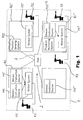
- Fig. 1 illustrates the general architecture of a control system according to the invention.
- Each robot R1-R4 is connected for signal transmission to a robot controller RC-RC'', whereby multiple robots R3, R4 can be connected to a common controller RC''.
- Each controller RC-RC" has an associated motion system MS-MS" and is arranged to receive motion instructions from at least one motion instruction source MIS-MIS (3) which can be either local to the controller, e.g. motion instruction sources MIS, MIS', MIS (3) or remote from the controller as is the case for controller RC' in Fig. 1.
- At least one MIS" of the motion instruction sources may be devised as a control program.
- the individual controllers are physically linked via a computer network 2, which in the embodiment shown in Fig. 1 comprises a hub 3 for communication distribution services.
- a computer network 2 which in the embodiment shown in Fig. 1 comprises a hub 3 for communication distribution services.
- An important point conveyed by Fig. 1 is that all aspects of the invention are valid whether motion instruction sources MIS-MIS (3) are on the same controller or different controllers.
- one robot controller RC' has a position sending system PSS for communicating positions of its attached robot R2 over the network 2.
- Another controller RC" has a corresponding position receiving system PRS for receiving said positions over the network 2.
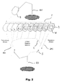
- Fig. 2 shows an example of linked motion involving two robots R1, R2.
- One robot R1 carries a part 4 along a motion trajectory T (though the latter need not be a straight line), while another robot R2 carries out a process relative to the part 4, such as arc welding along a weld line W.
- An important aspect of the invention illustrated in Fig. 2 is that the process robot R2 can rendezvous (rendezvous motion RM) and depart (depart motion DM) from the part 4 while the latter is in motion along the trajectory T.
- the two robots are in linked relative motion, robot R1 along the trajectory T and robot R2 along a generally curved trajectory L.
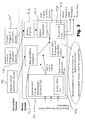
- the overall task architecture of the preferred embodiment is shown in Fig. 3. It assumes a tasking architecture which can be supported by many commercial real-time operating systems available today.
- the motion system task architecture is divided between motion instruction sources MIS-MIS" (cf. Fig. 1) which are internally or remotely connected to a motion system MS associated with a robot controller RC (Fig. 1).
- the motion system MS comprises a manual motion generator MS.1 in connection with manual motion instruction sources MIS, e.g. teaching pendants etc., if the latter are present.
- Software-implemented instruction sources i.e. control programs MIS', MIS" are connected to a motion planner MS.2 which relays information to a motion state manager and publisher MSP via a motion interpolator MS.3.
- Information generated by the motion generator MS.1 is relayed directly to the MSP.
- the MSP comprises a subscriber list MS.4 containing information, e.g. network addresses of multiple subscripers on the other controllers who have defined independent reference frames associated with robots attached to the present controller.
- These subscribers may include manual motion systems, planners, and interpolators such as MS.1, MS.2 and MS.3, respectively.
- Fig. 3 Further shown in Fig. 3 is an independent frame subscription service IFSS for gathering robot state messages from individual publishers, i.e. the MSPs of motion systems MS on another controller as shown in Fig. 3. Through a subscription list MS.5 the IFSS relates independent frames defined on the current controller to robot motion state publishers of other controllers.
- IFSS independent frame subscription service
- Multiple instruction sources MIS-MIS may be present simultaneously. This includes a manual motion source MIS and multiple control program instruction sources MIS', MIS''. The dotted line below these in Fig. 3 indicates that the instruction sources may reside on the same or different controller as the motion system controlling the robot (Fig. 1).
- the architecture shown permits continuous and persistent linking between a dependent reference frame on one robot and the independent reference frame defined on another robot while changing between motion instruction sources located anywhere and including either manual motion sources or control program instruction sources, and it includes such persistence even while no motion instruction is coming from any motion source.
- Various motions can be planned or executed which make use of multiple different independent reference frames simultaneously as shown by messages coming from multiple publishers to the Independent Frame Subscription Service IFSS and by that service's ability to update planners, inter-polars, and manual motion systems simultaneously. Functioning of the IFSS is described in detail below. In this way, it is possible to plan a motion from a currently moving independent reference frame to another moving independent reference frame, wherein such motion is to be started sometime in the future.
- the Motion State Manager is able to publish a robot's faceplate position to multiple subscribers simultaneously.
- the Planner MS.2 uses an estimate of the future position of an independent reference frame. In this way, when the actual motion in that frame begins, a correction factor is started and interpolated to nil by the Motion State Manager MSP. This is how motions between various moving reference frames can be handled smoothly and with advanced planning. These kinds of motions are generally transition motions that do not require substantial precision. Precision motions are generally generated in the same frame of reference, where no correction is needed between motions.
- the motion systems architecture can work in the presence of servo and interpolation clock synchronization between robot controllers or in the absence of such synchronization. There is also no requirement that the interpolation interval of two robot controllers be the same.
- Each component of the architecture assumes that wherever an independent frame is needed, its full state is available, including at least its velocity and position. Other derivatives, e.g. acceleration may optionally be present.
- each robot controller In the presence of clock synchronization, it is assumed that each robot controller generates its faceplate updates at the same rate and at nearly the same relative times within its interpolation interval. Chaining is then suppored in the following way: The MSP of each robot waits for up to a fixed amount of time for the frame update from its remote publisher, to which it is subscribed. This delay is sufficient for two or more successive robot controllers to compute their faceplate position and pass them on to their subscribers. All controllers will then update their servo systems at exactly the same time on the subsequent clock tick.
- a timeout from the above delay may occur.
- an estimate of the publisher's frame state is made, based on previously updated positions and velocities and the known time interval from the update time to the current time.
- the estimate of frame state is always used.
- the time interval between update and usage of said estimate is 0 clock intervals, and thus the position is accurate.
- the Motion State Publisher MSP can also act as a motion state manager.
- One of the key ideas of the invention is that it must be possible for a robot to remain in motion while there is no motion actually being generated on the controller for that particular robot.
- motion of the robot stops.
- motion stops when the operator lifts a button causing motion, motion stops.
- the MSP permits linked motion to continue in the absence of motion from the above entities.
- IFSS IFSS
- Planning of motions is generally done in advance of their actual execution: It is therefore possible that an assumed starting position is slightly different than the actual starting position, because in the case where the new motion is relative to a different frame than that of the current motion, that new frame might have taken a slightly different trajectory than assumed by the Planner or Manual Motion Generator.
- the MSP generates a small correction transformation at the beginning of each motion, so that such a transition motion from one frame to another frame is smooth.
- the correction transform is then interpolated to nil during the motion using a well known single-angle interpolation algorithm, so that the terminal position is exactly correct relative to the new frame.
- the single-angle interpolation algorithm determines the common normal vector between like coordinates of the assumed and actual starting position and then interpolates the rotation about that vector from actual to assumed starting position. This interpolation occurs linearly throughout the course of the motion.
- the MSP is responsible for the final calculation of the robot's faceplate position and joint angles for each interpolation interval. It is thus responsible for publishing that position to subscribers that have defined independent frames of reference relative to this robot's faceplate. This supports chaining of reference frames.
- the MSP additionally supports linking and chaining with and without servo and interpolation clock synchronization in the following way: When it requests independent frame state update from the IFSS it does so by specifying an allowable timeout value. The IFSS will then satisfy the update request with the actual update if it occurs prior to timeout (the normal case with clock synchronization) or with an estimate if the timeout occurs before an update takes place (possible without clock synchronization).
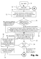
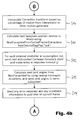
- the MSP performs the following operations:
- the MSP task first waits for the next interpolation cycle of the robot control in step S2, e.g. by repeatedly checking for a corresponding signal issued by a motion interpolator or other motion sources (not shown) as illustrated by loop S2'.
- Previous cycles of the MSP may have generated messages to subscriber tasks and entries for those messages may have been entered in a response Q.
- this response Q is checked. Positive responses from previous messages are simply removed. However, if no response came within a critical timeout period for an entry in this Q, this is a serious error. In case of a timeout for an entry in this Q, a STOP messages will be sent to the motion source (interpolator or manual motion generator).
- the MSP checks for relative motions in progress and for upcoming new relative motions, which are characterized by updates in Q. If there are such motions present, position is being updated and the MSP will get the next desired Cartesian state of a dependent frame from an interpolator or another motion generator (step S5).
- the state message also contains a description of the frame (e.g. in terms of axes' orientation) as well as information on tools, velocities and the percentage of motion that has already been carried out. The absence of such motions characterizes a stationary state relative to an independent frame such that previous values can be used for correction and desired position, and the task proceeds directly to step S6, wherein the MSP requests independent frame state update from the IFSS (Fig.
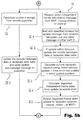
- the IFSS will respond within this timeout period with an update that represents an independent frame from a different controller in the same clock interval.
- the IFSS will usually timeout, and in that case it will estimate the independent frame position for the current time.
- step S7 the MSP checks whether or not this is the start of a new motion.
- the MSP assumes a new start position and calculates for a new frame a new initial correction transform (step S8).
- step S8 the correction transform for a new motion.
- step S11 is interpolated based on the percentage of motion from an interpolator or another motion generator.
- the MSP calculates a next faceplate position relative to World (step S11); for each external controller in the subscription list (Fig. 3), sends the next anticipated Cartesian state of the faceplate over the communication network (cf. Fig. 1) and makes corresponding entries in a Q (step S12) to check for responses from the faceplate messages in a subsequent cycle (step s3 of the next cycle); calculates next joint angles from the next faceplate position (cf. step S11) using inverse kinematics equations and sends joint angles to a servo subsystem (not shown; step S13); and sends any error response and scale back information to the publisher of the current frame (step S14).
- the IFSS is the second component along with the MSP that significantly differentiates the architecture of the present invention from the prior art.
- the IFSS performs the following basic functions:
- Each new frame request generates a new subscription ID, even if the frame is already being used. That ID is passed along from Planner to Interpolator, and to MSP. When the MSP is finished with a frame ID, it sends a release subscription message to IFSS. If said ID is the last ID remaining for a particular frame, that frame is released, and if the frame is the last one referencing a particular faceplate, an unsubscribe command is sent to the publisher, and the faceplate is released;
- the IFSS performs the following operations:
- step S1 Fig. 5a
- step S2 loop S2'
- a message can be 1) a new frame subscription message from manual motion or planners (step S3; Fig. 5a); 2) a remove frame subscription message from the MSP (sep S4; Fig. 5a); 3) a faceplate update message from a remote publisher (step S5; Fig. 5b); or 4) a request for latest independent frame information message from the MSP, manual motion or planner (step S6; Fig. 5b).
- step S2 If the message in step S2 is a new frame subscription message (step S3; Fig. 5a), then the IFSS checks in a subsequent step S3.1 whether or not subscription to that frame already exists. If a subscription exists, the task is resumed in step S3.5 (see below). Otherwise, in step S3.2 a new entry is created in a list of independent frames. Then, in step S3.3, it is checked whether or not a reference to the faceplate referenced by that independent frame already exists. If such a reference exists, the task is resumed in step S3.5, otherwise in step S3.4 an entry is created in a remote faceplate data table and a subscribe message sent to the faceplate publisher.
- step S3.5 the IFSS creates a subscription ID for the frame, with more than one ID possible for the same frame. Furtheron, the new ID is returned to the requestor, which can be a motion planner or a manual motion interface. The task is then continued in step S2.
- step S2 If the message in step S2 is a remove subscription message (step S4; Fig. 5a), then the subscription ID is removed from the frame (step S4.1) and the IFSS checks whether or not all IDs for that frame have been removed (step S4.2). If there are still some IDs left, the task is resumed in step S2. Otherwise, its entry is removed from the independent frame list (step S4.3). If all references to that particular faceplate have been deleted (step S4.4) then in step S4.5 a unsubscribe message is sent to the faceplate publisher and the remote faceplate is removed from the faceplate date table. Otherwise or afterwards, the task is resumed in step S2.
- step S2 If the message in step S2 is a faceplate update message (step S5; Fig. 5b) then the remote faceplate data is updated in the faceplate data table and a message sent to the publisher to acknowledge the update (step S5.1). The task is then resumed in step S2.
- step S2 If the message in step S2 is an independent frame request message (step S6; Fig. 5b), then the IFSS waits with specified timeout for an update message from a described faceplate. Any other messages are put in another wait queue (step S6.1). Step S6.1 is repeated until the update message is received as illustrated by loop S6.1'. Then in a subsequent step S6.2, the remote faceplate data in the faceplate data table is updated for an update within timeout (step S6.2). The IFSS then calculates current faceplate position in step S6.3 using: (latest velocity update) x (time since latest update) + (latest update position). In step S6.4, the requested independent frame state is calculated using the current faceplate calculated in step S6.3 plus the stored offset from the faceplate to the requested independent frame. In step S6.5, the requested frame state update is returned to the requester. The task is then resumed in step S2.
- the Planner task serves the basic function of calculating various parameters of the motion for later use by the interpolator.
- the planning of a motion is typically done a full motion ahead of the actual execution of a motion by the interpolator. This planning normally occurs in parallel with execution of the previously planned motion by the interpolator. In case where several motions are queued, i.e. waiting for execution, planning may occur several motions ahead of the actual interpolation of the motion.
- the beginning and ending states of the motion including at least starting position and velocity and ending position and velocity.
- TCP tool center point
- frame frame
- the states of the tool and frame for the motion must also be known at the time of planning.
- planning motions only for the robot attached to that controller and with no outside sensor influences, all required tool, frame, and starting state information is static and can thus be used at any time prior to the motion.
- each motion may be defined with respect to a new frame of reference, which may in turn be defined relative to a moving faceplate of a remote robot.
- the state of the frame needed for planning may not be up-to-date at precisely the time the planning is done. Even if planning were done at precisely the start of interpolation, unless clock synchronization is used, the independent frame information may not be exactly up-to-date at that time.
- a key aspect of the architecture in the preferred embodiment according to the invention is the IFSS, which supports estimation of future values of independent frames of reference defined relative to a remote faceplate.
- the IFSS will subscribe to and receive updates for the required remote robot. It will also convert the updated remote faceplate state to the independent frame of reference required by the Planner MS.2 (Fig. 3). Because full state information is maintained, including position and at least velocity of the independent frame, the Planner can then predict the position of the frame at the time the motion will be executed by the interpolator.
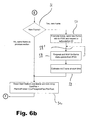
- step S2 After start of the Motion Planner in step S1 (Fig. 6a), it waits for a next Control Program Motion Instruction in step S2. Again, waiting is illustrated by loop S2'. After such an instruction has been given, the task checks in step S3 whether or not a new frame or tool has been added. If such a change has not occurred then it calculates parameters for the next motion in step S4. If the next motion is to be blended, i.e. a smooth transition between old and new motion states is to be performed, a new final motion is defined, placed back in the wait queue, and the current motion is planned as a blend motion, i.e. a motion that will join the new final motion smoothly in at least some of its parameters. Then, in step S5, an interpolation instruction record is sent to the interpolator queue, and the task is continued in step S2.
- a blend motion i.e. a motion that will join the new final motion smoothly in at least some of its parameters.
- step S3 If a new frame or tool is detected in step S3, then the task further distinguishes between situations with a new frame and situations without a new frame in step S6 (Fig. 6b): if a new frame is detected then, in step S7, for a remote frame the new frame information is sent to the IFSS together with a request for a subscription ID. Then, in step S8, the task waits and repeatedly checks (loop S8') for a frame update from the IFSS before estimating a independent frame at start time in step S9.
- step S10 a start state in the new frame and/or tool is reset.
- the task is then resumed in step S4 (Fig. 6a).
- the calculations performed in the Interpolator of the preferred embodiment are typical of existing robot controllers. However, instead of sending intermediate state information to a servo subsystem, in this case the state information is sent to the MSP, which in turn may apply a correction factor.
- the Interpolator passes its current percent of motion completion, so that the MSP may apply its interpolated correction factor for the same percentage of completion.
- the Interpolator passes the subscription ID of the independent frame and the tool to be used. The MSP will continue to use this same frame and tool for evaluating and updating dependent frame state after the motion is completed by the Interpolator.
- step S1 the interpolator task waits for a new motion in queue Q (step S2), which is checked repeatedly (loop S2'). When such motion has been detected the interpolator waits for the next tick of an interval clock (step S3; loop S3') and then calculates the next interpolated position of a current tool in a current frame (step S4). Current frame, tool, position, velocity in frame and motion percentage (percentage of motion already accomplished) are then sent to the MSP along with a subscription ID for any remote frames (step S5). In a subsequent step S6, the task performs a check as to whether or not the motion has ended. If this is the case, the task fetches another from the waiting queue in step S2, otherwise the task is resumed in step S3.
- the function of the Manual Motion Generator (MS.1; Fig. 3) is assumed to be typical of existing robot controllers, with the exception that it is modified in exactly the same way as previously described for the Planner to make use of estimated frames of reference from the IFSS and to pass interpolated state and subscription ID information to the MSP in a way similar to the Interpolator.
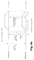
- Fig. 8 shows a timing diagram (timelines t) and simple linked motion of two robots R1, R2.
- Robot R1 carries a part 4 along a straight line T between end points P0World, P1World which are defined in World coordinates.
- Robot R2 moves a welding torch 5 to the part 4 while the latter is in motion, stops relative to the part 4, then departs from the part 4, and moves back to a point P2World defined relative to World. Following is a description of the communication that occurs during these motions:
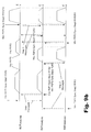
- Fig. 9a, 9b show timing diagrams for two different sets of time synchronized motions, a simple one and a complex one.
- the simple synchronized motion in Fig. 9a involves two robots R1, R2 each executing one time synchronized motion.
- Robot R1 is to move to a position R1P1 at the same time robot R2 moves to a position R2P1 (positions not shown in the diagram).
- the two control programs are arranged to recognize that they are to synchronize with each other for the motion with a same label, e.g. "Step 1". They also each know that they are to synchronize with the other because of the sync list, "R1R2" (R1 knows its partner is R2, R2 knows its partner is R1).
- the corresponding statements of the program code are given above and below the timelines t, respectively.
- Fig. 9a assumes that R1's control program arrives at its motion statement first, and its Planner issues a message to R2 saying that it is at label "Step1" and it will need 3.4 s to execute its motion. R1's Planner then waits for a message from R2.
- R2 arrives at its motion statement. Its Planner issues a message to R1 saying that it is at label "Step1" and it will need 2.8 s to execute its motion. R2 already has its message from R1. Its sync list is satisfied, and it knows the motion of R1 will take the longest of the two times, i.e. 3.4 s (vs. 2.8 s for R2). Its Planner finishes and issues a scaled motion planning with a duration of 3.4 s to its Interpolator. Scaled motion planing means that the speed of each robot is scaled slightly downward from its programmed value to maintain time coordination with the other robots. The robot taking the longest to execute its motion will dictate the scaling for all other robots. The Interpolator then waits for a "Go" signal from R1. (The robot taking the longest time issues the "Go"-signal.)
- R1's Planner When R1's Planner receives the message from R2, its sync list is then satisfied and it issues a motion to its Interpolator for 3.4 s. R1's Interpolator sends "Go" to R2, and they both begin interpolation.
- the "Go" signal is given at the beginning of both robots' interpolation cycles, and they both interpolate in lock step (with no need for communication other than clock synchronization).
- the registration between robots is extremely precise, as precise as the clock synchronization itself.
- FIG. 9b A much more complex series of synchronized motions is illustrated in Fig. 9b. It shows nine motions issued by control programs on three different robots R1-R3.
- Robot R1 issues four motions, two of which are synchronized with other robots.
- Robot R2 issues three motions, all of which are synchronized with other robots, and robot R3 issues two motions, both synchronized with other robots.
- the three synchronization labels are "Step1", “Step2” and "Step3".
- Robots R1 and R2 participate together at Step1.
- Robots R2 and R3 participate together at Step2.
- Robots R1, R2 and R3 participate together at Step3.
Landscapes
- Engineering & Computer Science (AREA)
- Robotics (AREA)
- Mechanical Engineering (AREA)
- Manipulator (AREA)
- Numerical Control (AREA)
Applications Claiming Priority (2)
| Application Number | Priority Date | Filing Date | Title |
|---|---|---|---|
| US10/406,521 US6804580B1 (en) | 2003-04-03 | 2003-04-03 | Method and control system for controlling a plurality of robots |
| US406521 | 2003-04-03 |
Publications (3)
| Publication Number | Publication Date |
|---|---|
| EP1464452A2 true EP1464452A2 (de) | 2004-10-06 |
| EP1464452A3 EP1464452A3 (de) | 2008-08-13 |
| EP1464452B1 EP1464452B1 (de) | 2011-02-23 |
Family
ID=32850647
Family Applications (1)
| Application Number | Title | Priority Date | Filing Date |
|---|---|---|---|
| EP04007908A Expired - Lifetime EP1464452B1 (de) | 2003-04-03 | 2004-04-01 | Verfahren und Steuerungssystem zum Steuern einer Mehrzahl von Robotern |
Country Status (5)
| Country | Link |
|---|---|
| US (1) | US6804580B1 (de) |
| EP (1) | EP1464452B1 (de) |
| AT (1) | ATE499184T1 (de) |
| DE (1) | DE602004031476D1 (de) |
| ES (1) | ES2361404T3 (de) |
Cited By (9)
| Publication number | Priority date | Publication date | Assignee | Title |
|---|---|---|---|---|
| WO2005068138A1 (en) * | 2004-01-16 | 2005-07-28 | Abb Ab | Control system, method and computer program for sychronizing several robots. |
| EP1705541A2 (de) | 2005-03-23 | 2006-09-27 | Kawasaki Jukogyo Kabushiki Kaisha | Robotersteuerung und Robotersteuerverfahren |
| WO2009140977A1 (de) * | 2008-05-21 | 2009-11-26 | Edag Gmbh & Co. Kgaa | Spannrahmenloses fügen von bauteilen |
| US7860609B2 (en) | 2005-05-06 | 2010-12-28 | Fanuc Robotics America, Inc. | Robot multi-arm control system |
| DE102010029745A1 (de) * | 2010-06-07 | 2011-12-08 | Kuka Laboratories Gmbh | Werkstück-Handhabungssystem und Verfahren zum Manipulieren von Werkstücken mittels kooperierender Manipulatoren |
| WO2017129360A1 (de) * | 2016-01-27 | 2017-08-03 | Kuka Roboter Gmbh | Steuern eines roboterverbands |
| WO2020157187A1 (de) * | 2019-01-31 | 2020-08-06 | Franka Emika Gmbh | Koordination von bahnen zweier robotermanipulatoren |
| CN113021330A (zh) * | 2019-12-24 | 2021-06-25 | 沈阳智能机器人创新中心有限公司 | 一种分布式网络下的多机器人同步随动控制方法 |
| EP3812110A4 (de) * | 2018-06-25 | 2022-03-09 | Kawasaki Jukogyo Kabushiki Kaisha | Robotersteuerungssystem |
Families Citing this family (161)
| Publication number | Priority date | Publication date | Assignee | Title |
|---|---|---|---|---|
| US20020138246A1 (en) * | 2001-03-08 | 2002-09-26 | Czora Gregory J. | System and method for simulating conciousness |
| JP4739556B2 (ja) * | 2001-03-27 | 2011-08-03 | 株式会社安川電機 | 制御対象の遠隔調整及び異常判断装置 |
| US6925357B2 (en) | 2002-07-25 | 2005-08-02 | Intouch Health, Inc. | Medical tele-robotic system |
| US20040162637A1 (en) | 2002-07-25 | 2004-08-19 | Yulun Wang | Medical tele-robotic system with a master remote station with an arbitrator |
| DE10236392A1 (de) * | 2002-08-08 | 2004-02-19 | Kuka Roboter Gmbh | Verfahren und Vorrichtung zum Steuern von Handhabungsgeräten |
| FR2853983A1 (fr) * | 2003-04-17 | 2004-10-22 | Philippe Bellanger | Procede et dispositif d'interaction pour l'assistance au geste "metier-matiere" |
| SE0301910L (sv) * | 2003-06-26 | 2004-12-27 | Abb Ab | Datorstyrd arbetsplats med robotar |
| DE10351670A1 (de) * | 2003-11-05 | 2005-06-30 | Kuka Roboter Gmbh | Verfahren und Vorrichtung zum Steuern von Robotern |
| US7813836B2 (en) | 2003-12-09 | 2010-10-12 | Intouch Technologies, Inc. | Protocol for a remotely controlled videoconferencing robot |
| SE0303384D0 (sv) * | 2003-12-15 | 2003-12-15 | Abb Ab | Control system, method and computer program |
| JP4325407B2 (ja) * | 2004-01-08 | 2009-09-02 | パナソニック株式会社 | 産業用ロボット |
| KR100590549B1 (ko) * | 2004-03-12 | 2006-06-19 | 삼성전자주식회사 | 3차원 포인팅 방법을 이용한 로봇의 원격 제어 방법 및이를 구현한 로봇 제어 시스템 |
| DE102004026185A1 (de) * | 2004-05-28 | 2005-12-22 | Kuka Roboter Gmbh | Verfahren und Vorrichtung zum Betreiben einer Maschine, wie eines Mehrachs- Industrieroboters |
| US8077963B2 (en) | 2004-07-13 | 2011-12-13 | Yulun Wang | Mobile robot with a head-based movement mapping scheme |
| EP1657552A1 (de) * | 2004-11-12 | 2006-05-17 | The Automation Partnership (Cambridge) Limited | Beladen/Entladen von Behälter |
| US7983769B2 (en) * | 2004-11-23 | 2011-07-19 | Rockwell Automation Technologies, Inc. | Time stamped motion control network protocol that enables balanced single cycle timing and utilization of dynamic data structures |
| US7904184B2 (en) * | 2004-11-23 | 2011-03-08 | Rockwell Automation Technologies, Inc. | Motion control timing models |
| US7149606B2 (en) * | 2005-03-01 | 2006-12-12 | Fanul Robotics America, Inc. | Synchronizing controllers linked by a communications network |
| JP2006277120A (ja) * | 2005-03-28 | 2006-10-12 | Toshiba Corp | オブジェクト管理装置、オブジェクト管理方法およびオブジェクト管理プログラム |
| US7904182B2 (en) * | 2005-06-08 | 2011-03-08 | Brooks Automation, Inc. | Scalable motion control system |
| US9198728B2 (en) | 2005-09-30 | 2015-12-01 | Intouch Technologies, Inc. | Multi-camera mobile teleconferencing platform |
| US7174474B1 (en) * | 2005-10-12 | 2007-02-06 | Avago Technologies Ecbu Ip (Singapore) Pte. Ltd. | Distributed autonomous control system for multi-axis motion control |
| US9794533B2 (en) | 2006-01-31 | 2017-10-17 | Andrew Flessas | Robotically controlled entertainment elements |
| US8356704B2 (en) | 2006-01-31 | 2013-01-22 | Andrew Flessas | Robotically controlled entertainment elements |
| ATE441885T1 (de) * | 2005-12-07 | 2009-09-15 | Sap Ag | Verfahren und system zum automatischen organisieren und ausführen einer vordefinierten aufgabe durch roboterfunktionalitäten |
| US11284048B2 (en) | 2006-01-31 | 2022-03-22 | Andrew Flessas | Robotically controlled display |
| US20100145512A1 (en) * | 2006-01-31 | 2010-06-10 | Andy Flessas | Method and system for transmitting robot control instructions |
| US9195233B2 (en) * | 2006-02-27 | 2015-11-24 | Perrone Robotics, Inc. | General purpose robotics operating system |
| US9833901B2 (en) | 2006-02-27 | 2017-12-05 | Perrone Robotics, Inc. | General purpose robotics operating system with unmanned and autonomous vehicle extensions |
| US10331136B2 (en) | 2006-02-27 | 2019-06-25 | Perrone Robotics, Inc. | General purpose robotics operating system with unmanned and autonomous vehicle extensions |
| US20070271002A1 (en) * | 2006-05-22 | 2007-11-22 | Hoskinson Reed L | Systems and methods for the autonomous control, automated guidance, and global coordination of moving process machinery |
| US8849679B2 (en) | 2006-06-15 | 2014-09-30 | Intouch Technologies, Inc. | Remote controlled robot system that provides medical images |
| US8355818B2 (en) | 2009-09-03 | 2013-01-15 | Battelle Energy Alliance, Llc | Robots, systems, and methods for hazard evaluation and visualization |
| US8073564B2 (en) * | 2006-07-05 | 2011-12-06 | Battelle Energy Alliance, Llc | Multi-robot control interface |
| US7801644B2 (en) * | 2006-07-05 | 2010-09-21 | Battelle Energy Alliance, Llc | Generic robot architecture |
| US7211980B1 (en) | 2006-07-05 | 2007-05-01 | Battelle Energy Alliance, Llc | Robotic follow system and method |
| US8965578B2 (en) | 2006-07-05 | 2015-02-24 | Battelle Energy Alliance, Llc | Real time explosive hazard information sensing, processing, and communication for autonomous operation |
| US7668621B2 (en) * | 2006-07-05 | 2010-02-23 | The United States Of America As Represented By The United States Department Of Energy | Robotic guarded motion system and method |
| US7974738B2 (en) * | 2006-07-05 | 2011-07-05 | Battelle Energy Alliance, Llc | Robotics virtual rail system and method |
| US8271132B2 (en) | 2008-03-13 | 2012-09-18 | Battelle Energy Alliance, Llc | System and method for seamless task-directed autonomy for robots |
| US7620477B2 (en) * | 2006-07-05 | 2009-11-17 | Battelle Energy Alliance, Llc | Robotic intelligence kernel |
| US7587260B2 (en) * | 2006-07-05 | 2009-09-08 | Battelle Energy Alliance, Llc | Autonomous navigation system and method |
| US7584020B2 (en) * | 2006-07-05 | 2009-09-01 | Battelle Energy Alliance, Llc | Occupancy change detection system and method |
| US8265793B2 (en) | 2007-03-20 | 2012-09-11 | Irobot Corporation | Mobile robot for telecommunication |
| US8086551B2 (en) | 2007-04-16 | 2011-12-27 | Blue Oak Mountain Technologies, Inc. | Electronic system with simulated sense perception and method of providing simulated sense perception |
| US9160783B2 (en) | 2007-05-09 | 2015-10-13 | Intouch Technologies, Inc. | Robot system that operates through a network firewall |
| KR100912874B1 (ko) * | 2007-06-28 | 2009-08-19 | 삼성전자주식회사 | 이동 로봇의 리로케이션 방법 및 장치 |
| IL185124A0 (en) * | 2007-08-08 | 2008-11-03 | Wave Group Ltd | A generic omni directional imaging system & method for vision, orientation and maneuver of robots |
| KR100945884B1 (ko) * | 2007-11-14 | 2010-03-05 | 삼성중공업 주식회사 | 내장형 로봇 제어 시스템 |
| US10875182B2 (en) | 2008-03-20 | 2020-12-29 | Teladoc Health, Inc. | Remote presence system mounted to operating room hardware |
| US8179418B2 (en) | 2008-04-14 | 2012-05-15 | Intouch Technologies, Inc. | Robotic based health care system |
| US8170241B2 (en) | 2008-04-17 | 2012-05-01 | Intouch Technologies, Inc. | Mobile tele-presence system with a microphone system |
| US9193065B2 (en) | 2008-07-10 | 2015-11-24 | Intouch Technologies, Inc. | Docking system for a tele-presence robot |
| US9842192B2 (en) | 2008-07-11 | 2017-12-12 | Intouch Technologies, Inc. | Tele-presence robot system with multi-cast features |
| US8948906B2 (en) * | 2008-08-14 | 2015-02-03 | Spectra Logic Corporation | Robotic storage library with queued move instructions and method of queuing such instructions |
| US8457778B2 (en) * | 2008-08-15 | 2013-06-04 | Spectra Logic Corp. | Robotic storage library with queued move instructions and method of queuing such instructions |
| US9046890B2 (en) * | 2008-09-05 | 2015-06-02 | Fanuc Robotics America, Inc. | Line tracking data over Ethernet |
| US8340819B2 (en) | 2008-09-18 | 2012-12-25 | Intouch Technologies, Inc. | Mobile videoconferencing robot system with network adaptive driving |
| US8996165B2 (en) | 2008-10-21 | 2015-03-31 | Intouch Technologies, Inc. | Telepresence robot with a camera boom |
| US8666537B2 (en) * | 2008-10-31 | 2014-03-04 | Spectra Logic, Corporation | Robotic storage library with queued move instructions and method of queing such instructions |
| US8340810B2 (en) * | 2008-10-31 | 2012-12-25 | Spectra Logic Corp. | Robotic storage library with queued move instructions and method of queuing such instructions |
| US8463435B2 (en) | 2008-11-25 | 2013-06-11 | Intouch Technologies, Inc. | Server connectivity control for tele-presence robot |
| US9138891B2 (en) | 2008-11-25 | 2015-09-22 | Intouch Technologies, Inc. | Server connectivity control for tele-presence robot |
| US20100180711A1 (en) | 2009-01-19 | 2010-07-22 | Comau, Inc. | Robotic end effector system and method |
| US8849680B2 (en) | 2009-01-29 | 2014-09-30 | Intouch Technologies, Inc. | Documentation through a remote presence robot |
| WO2010098030A1 (ja) * | 2009-02-25 | 2010-09-02 | パナソニック株式会社 | 溶接方法および溶接システム |
| US20100241260A1 (en) * | 2009-03-17 | 2010-09-23 | Comau, Inc. | Industrial communication system and method |
| US8676466B2 (en) * | 2009-04-06 | 2014-03-18 | GM Global Technology Operations LLC | Fail-safe speed profiles for cooperative autonomous vehicles |
| US8897920B2 (en) | 2009-04-17 | 2014-11-25 | Intouch Technologies, Inc. | Tele-presence robot system with software modularity, projector and laser pointer |
| US8384755B2 (en) * | 2009-08-26 | 2013-02-26 | Intouch Technologies, Inc. | Portable remote presence robot |
| US11399153B2 (en) | 2009-08-26 | 2022-07-26 | Teladoc Health, Inc. | Portable telepresence apparatus |
| WO2011029476A1 (en) | 2009-09-11 | 2011-03-17 | Abb Technology Ab | Improved pick and place |
| DE102009050646A1 (de) * | 2009-10-26 | 2011-04-28 | Kuka Roboter Gmbh | Verfahren und Vorrichtung zum Steuern einer Mehrmaschinenanordnung |
| CA2785558C (en) * | 2010-01-12 | 2016-05-10 | Comau, Inc. | Distributed control system |
| US11154981B2 (en) | 2010-02-04 | 2021-10-26 | Teladoc Health, Inc. | Robot user interface for telepresence robot system |
| US8670017B2 (en) | 2010-03-04 | 2014-03-11 | Intouch Technologies, Inc. | Remote presence system including a cart that supports a robot face and an overhead camera |
| US9012853B2 (en) | 2010-05-13 | 2015-04-21 | Flir Detection, Inc. | Radiation measurement using timing-over-ethernet protocol |
| US8918213B2 (en) | 2010-05-20 | 2014-12-23 | Irobot Corporation | Mobile human interface robot |
| US9014848B2 (en) | 2010-05-20 | 2015-04-21 | Irobot Corporation | Mobile robot system |
| US8935005B2 (en) | 2010-05-20 | 2015-01-13 | Irobot Corporation | Operating a mobile robot |
| US10343283B2 (en) | 2010-05-24 | 2019-07-09 | Intouch Technologies, Inc. | Telepresence robot system that can be accessed by a cellular phone |
| US10808882B2 (en) | 2010-05-26 | 2020-10-20 | Intouch Technologies, Inc. | Tele-robotic system with a robot face placed on a chair |
| US8731714B2 (en) * | 2010-09-22 | 2014-05-20 | GM Global Technology Operations LLC | Concurrent path planning with one or more humanoid robots |
| US8615322B2 (en) | 2010-09-27 | 2013-12-24 | Spectra Logic Corporation | Efficient moves via dual pickers |
| US8682471B2 (en) | 2010-09-27 | 2014-03-25 | Spectra Logic Corporation | Efficient magazine moves |
| US9264664B2 (en) | 2010-12-03 | 2016-02-16 | Intouch Technologies, Inc. | Systems and methods for dynamic bandwidth allocation |
| US8930019B2 (en) | 2010-12-30 | 2015-01-06 | Irobot Corporation | Mobile human interface robot |
| US12093036B2 (en) | 2011-01-21 | 2024-09-17 | Teladoc Health, Inc. | Telerobotic system with a dual application screen presentation |
| CN103459099B (zh) | 2011-01-28 | 2015-08-26 | 英塔茨科技公司 | 与一个可移动的远程机器人相互交流 |
| US9323250B2 (en) | 2011-01-28 | 2016-04-26 | Intouch Technologies, Inc. | Time-dependent navigation of telepresence robots |
| DE102011010505A1 (de) * | 2011-02-07 | 2012-08-09 | Dürr Systems GmbH | Anpassung der Dynamik zumindest eines Roboters |
| US11482326B2 (en) | 2011-02-16 | 2022-10-25 | Teladog Health, Inc. | Systems and methods for network-based counseling |
| US10769739B2 (en) | 2011-04-25 | 2020-09-08 | Intouch Technologies, Inc. | Systems and methods for management of information among medical providers and facilities |
| US20140139616A1 (en) | 2012-01-27 | 2014-05-22 | Intouch Technologies, Inc. | Enhanced Diagnostics for a Telepresence Robot |
| US9098611B2 (en) | 2012-11-26 | 2015-08-04 | Intouch Technologies, Inc. | Enhanced video interaction for a user interface of a telepresence network |
| US8639364B2 (en) * | 2011-07-13 | 2014-01-28 | KUKA Robotics Corporation | Uniform synchronizing robot control and deadlock detection in uniform synchronization |
| US8836751B2 (en) | 2011-11-08 | 2014-09-16 | Intouch Technologies, Inc. | Tele-presence system with a user interface that displays different communication links |
| US9251313B2 (en) | 2012-04-11 | 2016-02-02 | Intouch Technologies, Inc. | Systems and methods for visualizing and managing telepresence devices in healthcare networks |
| US8902278B2 (en) | 2012-04-11 | 2014-12-02 | Intouch Technologies, Inc. | Systems and methods for visualizing and managing telepresence devices in healthcare networks |
| US9361021B2 (en) | 2012-05-22 | 2016-06-07 | Irobot Corporation | Graphical user interfaces including touchpad driving interfaces for telemedicine devices |
| WO2013176758A1 (en) | 2012-05-22 | 2013-11-28 | Intouch Technologies, Inc. | Clinical workflows utilizing autonomous and semi-autonomous telemedicine devices |
| DE102012012184A1 (de) * | 2012-06-19 | 2013-12-19 | Kuka Roboter Gmbh | Vorgabe synchronisierter Roboterbewegungen |
| US9517556B2 (en) * | 2012-06-29 | 2016-12-13 | Mitsubishi Electric Corporation | Robot control apparatus and robot control method |
| EP3670112B1 (de) * | 2013-02-15 | 2025-10-29 | Intuitive Surgical Operations, Inc. | Systeme und verfahren zur synchronisierung von knoten eines robotersystems |
| JP6548662B2 (ja) * | 2014-03-17 | 2019-07-24 | インテュイティブ サージカル オペレーションズ, インコーポレイテッド | 処置中再始動の間の器具制御入力位置/向きの回復 |
| US9841749B2 (en) | 2014-04-01 | 2017-12-12 | Bot & Dolly, Llc | Runtime controller for robotic manufacturing system |
| US9555545B2 (en) * | 2014-05-21 | 2017-01-31 | Bot & Dolly, Llc | Systems and methods for time-based parallel robotic operation |
| US9050723B1 (en) | 2014-07-11 | 2015-06-09 | inVia Robotics, LLC | Human and robotic distributed operating system (HaRD-OS) |
| US9823693B2 (en) | 2014-08-26 | 2017-11-21 | Andrew Flessas | Robotically controlled convertible display |
| US9415512B2 (en) * | 2014-08-28 | 2016-08-16 | Fanuc America Corporation | System and method for enhancing a visualization of coordinate points within a robots working envelope |
| ES2654335T3 (es) | 2014-10-23 | 2018-02-13 | Comau S.P.A. | Sistema para monitorizar y controlar una instalación industrial |
| GB201509341D0 (en) | 2015-05-29 | 2015-07-15 | Cambridge Medical Robotics Ltd | Characterising robot environments |
| US10379007B2 (en) | 2015-06-24 | 2019-08-13 | Perrone Robotics, Inc. | Automated robotic test system for automated driving systems |
| DE102015008188B3 (de) * | 2015-06-25 | 2016-06-16 | Kuka Roboter Gmbh | Abfahren einer vorgegebenen Bahn mit einem Roboter |
| KR101962889B1 (ko) * | 2015-07-27 | 2019-03-28 | 한국전자통신연구원 | 작업환경 변화에 적응적인 로봇 동작 데이터 제공장치 및 그 방법 |
| WO2017121457A1 (en) * | 2016-01-11 | 2017-07-20 | Abb Schweiz Ag | A collaboration system and a method for operating the collaboration system |
| WO2017121456A1 (en) * | 2016-01-11 | 2017-07-20 | Abb Schweiz Ag | A robot system and a method for operating the robot system |
| US10393534B2 (en) | 2016-05-25 | 2019-08-27 | Here Global B.V. | Determining speed information |
| US10131361B2 (en) * | 2016-05-25 | 2018-11-20 | Here Global B.V. | Determining speed information |
| US10539967B2 (en) | 2016-08-23 | 2020-01-21 | King Fahd University Of Petroleum And Minerals | GPS-free robots |
| US10354526B2 (en) | 2016-12-01 | 2019-07-16 | Here Global B.V. | Determining lane specific speed information |
| JP6484213B2 (ja) * | 2016-12-09 | 2019-03-13 | ファナック株式会社 | 複数のロボットを含むロボットシステム、ロボット制御装置、及びロボット制御方法 |
| EP3366409B1 (de) | 2017-02-23 | 2019-08-07 | Comau S.p.A. | Gelenkroboter tragender einen kopf für elektrisches widerstandsschweissen mit elektroden auf derselben seite ; entsprechendes verfahren zum elektrischen widerstandschweissen an einem zu schweissenden komponenten |
| US20180272526A1 (en) * | 2017-03-21 | 2018-09-27 | Seiko Epson Corporation | Control device, teaching device, and robot system |
| US11862302B2 (en) | 2017-04-24 | 2024-01-02 | Teladoc Health, Inc. | Automated transcription and documentation of tele-health encounters |
| WO2018201240A1 (en) * | 2017-05-03 | 2018-11-08 | Taiga Robotics Corp. | Systems and methods for remotely controlling a robotic device |
| EP3403772B1 (de) * | 2017-05-18 | 2022-11-16 | KUKA Hungária Kft. | Roboterbewegungsplanung zur vermeidung von kollisionen mit bewegten hindernissen |
| US10483007B2 (en) | 2017-07-25 | 2019-11-19 | Intouch Technologies, Inc. | Modular telehealth cart with thermal imaging and touch screen user interface |
| US11636944B2 (en) | 2017-08-25 | 2023-04-25 | Teladoc Health, Inc. | Connectivity infrastructure for a telehealth platform |
| US12138778B1 (en) | 2017-09-13 | 2024-11-12 | AI Incorporated | Control system for robotic devices |
| JP6662926B2 (ja) * | 2018-01-31 | 2020-03-11 | ファナック株式会社 | ロボットおよびロボットに関する保守時期の報知方法 |
| US10617299B2 (en) | 2018-04-27 | 2020-04-14 | Intouch Technologies, Inc. | Telehealth cart that supports a removable tablet with seamless audio/video switching |
| IT201800005091A1 (it) | 2018-05-04 | 2019-11-04 | "Procedimento per monitorare lo stato di funzionamento di una stazione di lavorazione, relativo sistema di monitoraggio e prodotto informatico" | |
| US11000950B2 (en) | 2018-06-01 | 2021-05-11 | X Development Llc | Robotic motion planning |
| SG11202010173TA (en) * | 2018-06-22 | 2020-11-27 | Soft Servo Systems Inc | Motion control program, motion control method, and motion control device |
| US11110606B2 (en) * | 2019-01-02 | 2021-09-07 | The Boeing Company | Coordinating work within a multi-robot cell |
| US11154986B2 (en) | 2019-01-24 | 2021-10-26 | Intrinsic Innovation Llc | Local replanning of robot movements |
| JP7417356B2 (ja) * | 2019-01-25 | 2024-01-18 | 株式会社ソニー・インタラクティブエンタテインメント | ロボット制御システム |
| JP7309371B2 (ja) | 2019-01-25 | 2023-07-18 | 株式会社ソニー・インタラクティブエンタテインメント | ロボット制御システム |
| JP7190919B2 (ja) | 2019-01-25 | 2022-12-16 | 株式会社ソニー・インタラクティブエンタテインメント | 画像解析システム |
| JP7205972B2 (ja) * | 2019-05-24 | 2023-01-17 | 川崎重工業株式会社 | 教示システム |
| JP7318406B2 (ja) * | 2019-08-07 | 2023-08-01 | オムロン株式会社 | 制御装置 |
| WO2021040714A1 (en) | 2019-08-29 | 2021-03-04 | Flessas Andrew | Method and system for moving cameras using robotic mounts |
| US11526823B1 (en) | 2019-12-27 | 2022-12-13 | Intrinsic Innovation Llc | Scheduling resource-constrained actions |
| JP7436659B2 (ja) * | 2020-05-25 | 2024-02-21 | ファナック株式会社 | ロボットシステム |
| WO2022016152A1 (en) | 2020-07-17 | 2022-01-20 | Path Robotics, Inc. | Real time feedback and dynamic adjustment for welding robots |
| JP2023533919A (ja) | 2020-08-19 | 2023-08-07 | 北京術鋭機器人股▲ふん▼有限公司 | ロボットシステムおよび制御方法 |
| CN112247985B (zh) * | 2020-09-21 | 2021-12-14 | 珠海格力电器股份有限公司 | 时钟同步方法、机器人控制系统和机器人 |
| US11425308B2 (en) | 2020-12-02 | 2022-08-23 | Andrew Flessas | Robotically movable display synchronously movable with robotically movable camera for displaying captured images in identical orientation |
| US11518024B2 (en) | 2021-02-10 | 2022-12-06 | Intrinsic Innovation Llc | Extensible underconstrained robotic motion planning |
| MX2023009878A (es) | 2021-02-24 | 2024-01-08 | Path Robotics Inc | Robots soldadores autonomos. |
| US12589485B2 (en) * | 2021-03-02 | 2026-03-31 | Fanuc Corporation | Teaching point generation device that generates teaching points on basis of output of sensor, and teaching point generation method |
| EP4313501A1 (de) * | 2021-03-25 | 2024-02-07 | ABB Schweiz AG | Bahnplanung für robotersystem |
| US12277369B2 (en) | 2021-10-18 | 2025-04-15 | Path Robotics, Inc. | Generating simulated weld paths for a welding robot |
| CA3239078A1 (en) | 2021-11-19 | 2023-05-25 | Path Robotics, Inc. | Machine learning logic-based adjustment techniques for robots |
| KR102785447B1 (ko) * | 2021-11-24 | 2025-03-25 | 알에스오토메이션주식회사 | 통신 환경용 모션 생성 알고리즘을 구비한 모션 제어 장치 |
| US12115670B2 (en) | 2021-12-15 | 2024-10-15 | Intrinsic Innovation Llc | Equipment specific motion plan generation for robotic skill adaptation |
| US12508665B2 (en) * | 2022-04-19 | 2025-12-30 | Path Robotics, Inc. | Autonomous assembly robots |
| US12521884B2 (en) | 2022-07-26 | 2026-01-13 | Path Robotics, Inc. | Techniques for multipass welding |
| DE202022105610U1 (de) | 2022-10-04 | 2024-01-05 | Kuka Deutschland Gmbh | Robotersteuerungssystem |
| CN117348501B (zh) * | 2023-12-05 | 2024-02-13 | 深圳市大族封测科技股份有限公司 | 一种多运动控制卡的联动控制方法及联动控制系统 |
Citations (2)
| Publication number | Priority date | Publication date | Assignee | Title |
|---|---|---|---|---|
| US6330493B1 (en) | 1999-09-16 | 2001-12-11 | Fanuc Ltd. | Control system for synchronously cooperative operation of plurality of robots |
| EP1468791A1 (de) | 2001-11-07 | 2004-10-20 | Kawasaki Jukogyo Kabushiki Kaisha | System zur steuerung von roboterkoordination |
Family Cites Families (11)
| Publication number | Priority date | Publication date | Assignee | Title |
|---|---|---|---|---|
| US5125298A (en) * | 1983-11-14 | 1992-06-30 | Smith Chalmers O | Automatic wheel assembly mounting system |
| WO1999067067A1 (en) * | 1998-06-23 | 1999-12-29 | Sony Corporation | Robot and information processing system |
| JP3951079B2 (ja) * | 1998-09-14 | 2007-08-01 | 株式会社安川電機 | オフラインティーチング方法、オフラインティーチング装置および記録媒体 |
| US6560511B1 (en) * | 1999-04-30 | 2003-05-06 | Sony Corporation | Electronic pet system, network system, robot, and storage medium |
| JP4122652B2 (ja) * | 1999-09-27 | 2008-07-23 | 松下電器産業株式会社 | ロボットの制御装置 |
| US6374155B1 (en) * | 1999-11-24 | 2002-04-16 | Personal Robotics, Inc. | Autonomous multi-platform robot system |
| JP2001252884A (ja) * | 2000-03-06 | 2001-09-18 | Matsushita Electric Ind Co Ltd | ロボット、ロボットシステムおよびロボットの制御方法 |
| JP2001269884A (ja) * | 2000-03-28 | 2001-10-02 | Matsushita Electric Ind Co Ltd | 産業用ロボット |
| DE10032096A1 (de) * | 2000-07-01 | 2002-01-24 | Kuka Roboter Gmbh | Geräteverbund und Steuerschrank für einen solchen |
| US6442451B1 (en) * | 2000-12-28 | 2002-08-27 | Robotic Workspace Technologies, Inc. | Versatile robot control system |
| US6516248B2 (en) * | 2001-06-07 | 2003-02-04 | Fanuc Robotics North America | Robot calibration system and method of determining a position of a robot relative to an electrically-charged calibration object |
-
2003
- 2003-04-03 US US10/406,521 patent/US6804580B1/en not_active Expired - Lifetime
-
2004
- 2004-04-01 ES ES04007908T patent/ES2361404T3/es not_active Expired - Lifetime
- 2004-04-01 EP EP04007908A patent/EP1464452B1/de not_active Expired - Lifetime
- 2004-04-01 DE DE602004031476T patent/DE602004031476D1/de not_active Expired - Lifetime
- 2004-04-01 AT AT04007908T patent/ATE499184T1/de not_active IP Right Cessation
Patent Citations (2)
| Publication number | Priority date | Publication date | Assignee | Title |
|---|---|---|---|---|
| US6330493B1 (en) | 1999-09-16 | 2001-12-11 | Fanuc Ltd. | Control system for synchronously cooperative operation of plurality of robots |
| EP1468791A1 (de) | 2001-11-07 | 2004-10-20 | Kawasaki Jukogyo Kabushiki Kaisha | System zur steuerung von roboterkoordination |
Cited By (16)
| Publication number | Priority date | Publication date | Assignee | Title |
|---|---|---|---|---|
| WO2005068138A1 (en) * | 2004-01-16 | 2005-07-28 | Abb Ab | Control system, method and computer program for sychronizing several robots. |
| US7620478B2 (en) | 2004-01-16 | 2009-11-17 | Abb Ab | Control system, method and computer program for synchronizing several robots |
| EP1705541A2 (de) | 2005-03-23 | 2006-09-27 | Kawasaki Jukogyo Kabushiki Kaisha | Robotersteuerung und Robotersteuerverfahren |
| EP1705541A3 (de) * | 2005-03-23 | 2008-08-06 | Kawasaki Jukogyo Kabushiki Kaisha | Robotersteuerung und Robotersteuerverfahren |
| US7729804B2 (en) | 2005-03-23 | 2010-06-01 | Kawasaki Jukogyo Kabushiki Kaisha | Robot controller and robot control method for synchronous operation and adjusting robot movement based on two movement times |
| US7860609B2 (en) | 2005-05-06 | 2010-12-28 | Fanuc Robotics America, Inc. | Robot multi-arm control system |
| WO2009140977A1 (de) * | 2008-05-21 | 2009-11-26 | Edag Gmbh & Co. Kgaa | Spannrahmenloses fügen von bauteilen |
| EP2392435A3 (de) * | 2010-06-07 | 2013-05-01 | KUKA Laboratories GmbH | Werkzeug-Handhabungssystem und Verfahren zum Manipulieren von Werkstücken mittels kooperierender Manipulatoren |
| DE102010029745A1 (de) * | 2010-06-07 | 2011-12-08 | Kuka Laboratories Gmbh | Werkstück-Handhabungssystem und Verfahren zum Manipulieren von Werkstücken mittels kooperierender Manipulatoren |
| WO2017129360A1 (de) * | 2016-01-27 | 2017-08-03 | Kuka Roboter Gmbh | Steuern eines roboterverbands |
| EP3812110A4 (de) * | 2018-06-25 | 2022-03-09 | Kawasaki Jukogyo Kabushiki Kaisha | Robotersteuerungssystem |
| WO2020157187A1 (de) * | 2019-01-31 | 2020-08-06 | Franka Emika Gmbh | Koordination von bahnen zweier robotermanipulatoren |
| CN113302026A (zh) * | 2019-01-31 | 2021-08-24 | 富兰卡爱米卡股份有限公司 | 两个机器人机械手的路径的协调 |
| JP2022519248A (ja) * | 2019-01-31 | 2022-03-22 | フランカ エーミカ ゲーエムベーハー | 2つのロボットマニピュレータの経路の調整 |
| CN113021330A (zh) * | 2019-12-24 | 2021-06-25 | 沈阳智能机器人创新中心有限公司 | 一种分布式网络下的多机器人同步随动控制方法 |
| CN113021330B (zh) * | 2019-12-24 | 2022-04-05 | 沈阳智能机器人创新中心有限公司 | 一种分布式网络下的多机器人同步随动控制方法 |
Also Published As
| Publication number | Publication date |
|---|---|
| EP1464452B1 (de) | 2011-02-23 |
| US6804580B1 (en) | 2004-10-12 |
| ES2361404T3 (es) | 2011-06-16 |
| US20040199290A1 (en) | 2004-10-07 |
| EP1464452A3 (de) | 2008-08-13 |
| DE602004031476D1 (de) | 2011-04-07 |
| ATE499184T1 (de) | 2011-03-15 |
Similar Documents
| Publication | Publication Date | Title |
|---|---|---|
| EP1464452B1 (de) | Verfahren und Steuerungssystem zum Steuern einer Mehrzahl von Robotern | |
| JP5530479B2 (ja) | 少なくとも2本のロボットアームの同期化システムおよびその制御方法 | |
| US7149606B2 (en) | Synchronizing controllers linked by a communications network | |
| CN111026164B (zh) | 一种机器人目标跟踪轨迹规划方法 | |
| US7282882B2 (en) | Robot controller | |
| JP2017027501A (ja) | 工作機械とロボットのリアルタイム干渉確認システム | |
| EP1704025B1 (de) | Steuersystem, verfahren und rechnerprogramm zur synchronisierung mehrerer roboter | |
| JP2018187746A (ja) | ロボット制御装置及びロボット制御プログラム | |
| JP7423726B2 (ja) | ロボットシステム、ロボットシステムの制御方法、ロボットシステムを用いた物品の製造方法、制御装置、操作装置、操作装置の制御方法、撮像装置、撮像装置の制御方法、制御プログラム及び記録媒体 | |
| EP3540537A1 (de) | Steuerungsvorrichtung, steuerungsverfahren und programm | |
| CN111522313B (zh) | 一种基于canopen协议控制伺服电机曲线运动的方法 | |
| EP4184265A1 (de) | System und verfahren zur verwaltung von automatisierungssystemen mit synchronen elementen | |
| EP3992735B1 (de) | Steuerungsvorrichtung | |
| JPH07141010A (ja) | 溶接用ロボットの制御方法 | |
| US12510882B2 (en) | Method for controlling a plurality of execution mechanisms, electronic device, and storage medium | |
| JP2772230B2 (ja) | オフラインティーチング装置 | |
| Shengzhong et al. | Multi Robot Flexible Welding Control for Complex Environment Tasks | |
| CN121470176A (zh) | 一种车身侧围抓取装置及方法 | |
| Zhang et al. | Agent-based modeling and control of remote robotic welding system | |
| KR20050001607A (ko) | 주행축을 포함하는 로봇 시스템의 협조 제어 방법 | |
| CN120215342A (zh) | 通用的工业机器人控制系统 | |
| CN114995308A (zh) | 一种基于工业级5g的机器人协作方法和系统 | |
| JPH09244731A (ja) | ロボット装置の運転方法 |
Legal Events
| Date | Code | Title | Description |
|---|---|---|---|
| PUAI | Public reference made under article 153(3) epc to a published international application that has entered the european phase |
Free format text: ORIGINAL CODE: 0009012 |
|
| AK | Designated contracting states |
Kind code of ref document: A2 Designated state(s): AT BE BG CH CY CZ DE DK EE ES FI FR GB GR HU IE IT LI LU MC NL PL PT RO SE SI SK TR |
|
| AX | Request for extension of the european patent |
Extension state: AL HR LT LV MK |
|
| RIN1 | Information on inventor provided before grant (corrected) |
Inventor name: HAGENAUER, ANDREAS Inventor name: STODDARD, KENNETH A. Inventor name: MARTIN, DAVID M. Inventor name: GRAF, STEFAN Inventor name: KNEIFEL II, R.WILLIAM Inventor name: CHAFFEE, MICHAEL C. Inventor name: MIRZA, KHALID |
|
| PUAL | Search report despatched |
Free format text: ORIGINAL CODE: 0009013 |
|
| AK | Designated contracting states |
Kind code of ref document: A3 Designated state(s): AT BE BG CH CY CZ DE DK EE ES FI FR GB GR HU IE IT LI LU MC NL PL PT RO SE SI SK TR |
|
| AX | Request for extension of the european patent |
Extension state: AL HR LT LV MK |
|
| 17P | Request for examination filed |
Effective date: 20081205 |
|
| AKX | Designation fees paid |
Designated state(s): AT BE BG CH CY CZ DE DK EE ES FI FR GB GR HU IE IT LI LU MC NL PL PT RO SE SI SK TR |
|
| 17Q | First examination report despatched |
Effective date: 20100217 |
|
| GRAP | Despatch of communication of intention to grant a patent |
Free format text: ORIGINAL CODE: EPIDOSNIGR1 |
|
| RAP1 | Party data changed (applicant data changed or rights of an application transferred) |
Owner name: KUKA ROBOTER GMBH |
|
| GRAS | Grant fee paid |
Free format text: ORIGINAL CODE: EPIDOSNIGR3 |
|
| GRAA | (expected) grant |
Free format text: ORIGINAL CODE: 0009210 |
|
| AK | Designated contracting states |
Kind code of ref document: B1 Designated state(s): AT BE BG CH CY CZ DE DK EE ES FI FR GB GR HU IE IT LI LU MC NL PL PT RO SE SI SK TR |
|
| REG | Reference to a national code |
Ref country code: GB Ref legal event code: FG4D |
|
| REG | Reference to a national code |
Ref country code: CH Ref legal event code: EP |
|
| REG | Reference to a national code |
Ref country code: IE Ref legal event code: FG4D |
|
| REF | Corresponds to: |
Ref document number: 602004031476 Country of ref document: DE Date of ref document: 20110407 Kind code of ref document: P |
|
| REG | Reference to a national code |
Ref country code: DE Ref legal event code: R096 Ref document number: 602004031476 Country of ref document: DE Effective date: 20110407 |
|
| REG | Reference to a national code |
Ref country code: ES Ref legal event code: FG2A Ref document number: 2361404 Country of ref document: ES Kind code of ref document: T3 Effective date: 20110616 |
|
| REG | Reference to a national code |
Ref country code: NL Ref legal event code: VDEP Effective date: 20110223 |
|
| PG25 | Lapsed in a contracting state [announced via postgrant information from national office to epo] |
Ref country code: SE Free format text: LAPSE BECAUSE OF FAILURE TO SUBMIT A TRANSLATION OF THE DESCRIPTION OR TO PAY THE FEE WITHIN THE PRESCRIBED TIME-LIMIT Effective date: 20110223 Ref country code: PT Free format text: LAPSE BECAUSE OF FAILURE TO SUBMIT A TRANSLATION OF THE DESCRIPTION OR TO PAY THE FEE WITHIN THE PRESCRIBED TIME-LIMIT Effective date: 20110623 Ref country code: GR Free format text: LAPSE BECAUSE OF FAILURE TO SUBMIT A TRANSLATION OF THE DESCRIPTION OR TO PAY THE FEE WITHIN THE PRESCRIBED TIME-LIMIT Effective date: 20110524 |
|
| PG25 | Lapsed in a contracting state [announced via postgrant information from national office to epo] |
Ref country code: NL Free format text: LAPSE BECAUSE OF FAILURE TO SUBMIT A TRANSLATION OF THE DESCRIPTION OR TO PAY THE FEE WITHIN THE PRESCRIBED TIME-LIMIT Effective date: 20110223 Ref country code: FI Free format text: LAPSE BECAUSE OF FAILURE TO SUBMIT A TRANSLATION OF THE DESCRIPTION OR TO PAY THE FEE WITHIN THE PRESCRIBED TIME-LIMIT Effective date: 20110223 Ref country code: BG Free format text: LAPSE BECAUSE OF FAILURE TO SUBMIT A TRANSLATION OF THE DESCRIPTION OR TO PAY THE FEE WITHIN THE PRESCRIBED TIME-LIMIT Effective date: 20110523 Ref country code: SI Free format text: LAPSE BECAUSE OF FAILURE TO SUBMIT A TRANSLATION OF THE DESCRIPTION OR TO PAY THE FEE WITHIN THE PRESCRIBED TIME-LIMIT Effective date: 20110223 Ref country code: CY Free format text: LAPSE BECAUSE OF FAILURE TO SUBMIT A TRANSLATION OF THE DESCRIPTION OR TO PAY THE FEE WITHIN THE PRESCRIBED TIME-LIMIT Effective date: 20110223 Ref country code: BE Free format text: LAPSE BECAUSE OF FAILURE TO SUBMIT A TRANSLATION OF THE DESCRIPTION OR TO PAY THE FEE WITHIN THE PRESCRIBED TIME-LIMIT Effective date: 20110223 Ref country code: AT Free format text: LAPSE BECAUSE OF FAILURE TO SUBMIT A TRANSLATION OF THE DESCRIPTION OR TO PAY THE FEE WITHIN THE PRESCRIBED TIME-LIMIT Effective date: 20110223 |
|
| PG25 | Lapsed in a contracting state [announced via postgrant information from national office to epo] |
Ref country code: EE Free format text: LAPSE BECAUSE OF FAILURE TO SUBMIT A TRANSLATION OF THE DESCRIPTION OR TO PAY THE FEE WITHIN THE PRESCRIBED TIME-LIMIT Effective date: 20110223 Ref country code: DK Free format text: LAPSE BECAUSE OF FAILURE TO SUBMIT A TRANSLATION OF THE DESCRIPTION OR TO PAY THE FEE WITHIN THE PRESCRIBED TIME-LIMIT Effective date: 20110223 |
|
| PG25 | Lapsed in a contracting state [announced via postgrant information from national office to epo] |
Ref country code: CZ Free format text: LAPSE BECAUSE OF FAILURE TO SUBMIT A TRANSLATION OF THE DESCRIPTION OR TO PAY THE FEE WITHIN THE PRESCRIBED TIME-LIMIT Effective date: 20110223 Ref country code: SK Free format text: LAPSE BECAUSE OF FAILURE TO SUBMIT A TRANSLATION OF THE DESCRIPTION OR TO PAY THE FEE WITHIN THE PRESCRIBED TIME-LIMIT Effective date: 20110223 Ref country code: MC Free format text: LAPSE BECAUSE OF NON-PAYMENT OF DUE FEES Effective date: 20110430 Ref country code: RO Free format text: LAPSE BECAUSE OF FAILURE TO SUBMIT A TRANSLATION OF THE DESCRIPTION OR TO PAY THE FEE WITHIN THE PRESCRIBED TIME-LIMIT Effective date: 20110223 |
|
| REG | Reference to a national code |
Ref country code: CH Ref legal event code: PL |
|
| PLBE | No opposition filed within time limit |
Free format text: ORIGINAL CODE: 0009261 |
|
| STAA | Information on the status of an ep patent application or granted ep patent |
Free format text: STATUS: NO OPPOSITION FILED WITHIN TIME LIMIT |
|
| GBPC | Gb: european patent ceased through non-payment of renewal fee |
Effective date: 20110523 |
|
| PG25 | Lapsed in a contracting state [announced via postgrant information from national office to epo] |
Ref country code: CH Free format text: LAPSE BECAUSE OF NON-PAYMENT OF DUE FEES Effective date: 20110430 Ref country code: LI Free format text: LAPSE BECAUSE OF NON-PAYMENT OF DUE FEES Effective date: 20110430 |
|
| 26N | No opposition filed |
Effective date: 20111124 |
|
| REG | Reference to a national code |
Ref country code: IE Ref legal event code: MM4A |
|
| PG25 | Lapsed in a contracting state [announced via postgrant information from national office to epo] |
Ref country code: PL Free format text: LAPSE BECAUSE OF FAILURE TO SUBMIT A TRANSLATION OF THE DESCRIPTION OR TO PAY THE FEE WITHIN THE PRESCRIBED TIME-LIMIT Effective date: 20110223 |
|
| REG | Reference to a national code |
Ref country code: DE Ref legal event code: R097 Ref document number: 602004031476 Country of ref document: DE Effective date: 20111124 |
|
| PG25 | Lapsed in a contracting state [announced via postgrant information from national office to epo] |
Ref country code: IE Free format text: LAPSE BECAUSE OF NON-PAYMENT OF DUE FEES Effective date: 20110401 |
|
| PG25 | Lapsed in a contracting state [announced via postgrant information from national office to epo] |
Ref country code: GB Free format text: LAPSE BECAUSE OF NON-PAYMENT OF DUE FEES Effective date: 20110523 |
|
| PG25 | Lapsed in a contracting state [announced via postgrant information from national office to epo] |
Ref country code: LU Free format text: LAPSE BECAUSE OF NON-PAYMENT OF DUE FEES Effective date: 20110401 |
|
| PG25 | Lapsed in a contracting state [announced via postgrant information from national office to epo] |
Ref country code: TR Free format text: LAPSE BECAUSE OF FAILURE TO SUBMIT A TRANSLATION OF THE DESCRIPTION OR TO PAY THE FEE WITHIN THE PRESCRIBED TIME-LIMIT Effective date: 20110223 |
|
| PG25 | Lapsed in a contracting state [announced via postgrant information from national office to epo] |
Ref country code: HU Free format text: LAPSE BECAUSE OF FAILURE TO SUBMIT A TRANSLATION OF THE DESCRIPTION OR TO PAY THE FEE WITHIN THE PRESCRIBED TIME-LIMIT Effective date: 20110223 |
|
| REG | Reference to a national code |
Ref country code: DE Ref legal event code: R082 Ref document number: 602004031476 Country of ref document: DE |
|
| REG | Reference to a national code |
Ref country code: FR Ref legal event code: PLFP Year of fee payment: 13 |
|
| REG | Reference to a national code |
Ref country code: FR Ref legal event code: PLFP Year of fee payment: 14 |
|
| REG | Reference to a national code |
Ref country code: FR Ref legal event code: PLFP Year of fee payment: 15 |
|
| REG | Reference to a national code |
Ref country code: DE Ref legal event code: R081 Ref document number: 602004031476 Country of ref document: DE Owner name: KUKA DEUTSCHLAND GMBH, DE Free format text: FORMER OWNER: KUKA ROBOTER GMBH, 86165 AUGSBURG, DE |
|
| PGFP | Annual fee paid to national office [announced via postgrant information from national office to epo] |
Ref country code: ES Payment date: 20190503 Year of fee payment: 16 |
|
| PGFP | Annual fee paid to national office [announced via postgrant information from national office to epo] |
Ref country code: FR Payment date: 20200312 Year of fee payment: 17 |
|
| PGFP | Annual fee paid to national office [announced via postgrant information from national office to epo] |
Ref country code: DE Payment date: 20200317 Year of fee payment: 17 |
|
| PGFP | Annual fee paid to national office [announced via postgrant information from national office to epo] |
Ref country code: IT Payment date: 20200312 Year of fee payment: 17 |
|
| REG | Reference to a national code |
Ref country code: ES Ref legal event code: FD2A Effective date: 20210826 |
|
| REG | Reference to a national code |
Ref country code: DE Ref legal event code: R119 Ref document number: 602004031476 Country of ref document: DE |
|
| PG25 | Lapsed in a contracting state [announced via postgrant information from national office to epo] |
Ref country code: DE Free format text: LAPSE BECAUSE OF NON-PAYMENT OF DUE FEES Effective date: 20211103 Ref country code: FR Free format text: LAPSE BECAUSE OF NON-PAYMENT OF DUE FEES Effective date: 20210430 |
|
| PG25 | Lapsed in a contracting state [announced via postgrant information from national office to epo] |
Ref country code: ES Free format text: LAPSE BECAUSE OF NON-PAYMENT OF DUE FEES Effective date: 20200402 |
|
| PG25 | Lapsed in a contracting state [announced via postgrant information from national office to epo] |
Ref country code: IT Free format text: LAPSE BECAUSE OF NON-PAYMENT OF DUE FEES Effective date: 20200401 |
|
| PG25 | Lapsed in a contracting state [announced via postgrant information from national office to epo] |
Ref country code: IT Free format text: LAPSE BECAUSE OF NON-PAYMENT OF DUE FEES Effective date: 20210401 |