EP1464669B1 - Mikroporöse polyolefinmembran - Google Patents
Mikroporöse polyolefinmembran Download PDFInfo
- Publication number
- EP1464669B1 EP1464669B1 EP03791293.8A EP03791293A EP1464669B1 EP 1464669 B1 EP1464669 B1 EP 1464669B1 EP 03791293 A EP03791293 A EP 03791293A EP 1464669 B1 EP1464669 B1 EP 1464669B1
- Authority
- EP
- European Patent Office
- Prior art keywords
- microporous membrane
- temperature
- stretching
- intrinsic viscosity
- membrane
- Prior art date
- Legal status (The legal status is an assumption and is not a legal conclusion. Google has not performed a legal analysis and makes no representation as to the accuracy of the status listed.)
- Expired - Lifetime
Links
- 239000012982 microporous membrane Substances 0.000 title claims description 124
- 229920000098 polyolefin Polymers 0.000 title claims description 32
- VYPSYNLAJGMNEJ-UHFFFAOYSA-N Silicium dioxide Chemical compound O=[Si]=O VYPSYNLAJGMNEJ-UHFFFAOYSA-N 0.000 claims description 102
- 239000012528 membrane Substances 0.000 claims description 61
- 239000000377 silicon dioxide Substances 0.000 claims description 51
- 229920001903 high density polyethylene Polymers 0.000 claims description 29
- 239000004700 high-density polyethylene Substances 0.000 claims description 29
- 239000004699 Ultra-high molecular weight polyethylene Substances 0.000 claims description 25
- 229920000785 ultra high molecular weight polyethylene Polymers 0.000 claims description 25
- 230000005540 biological transmission Effects 0.000 claims description 24
- 238000000034 method Methods 0.000 claims description 23
- 239000000203 mixture Substances 0.000 claims description 13
- 239000011800 void material Substances 0.000 claims description 12
- 239000011344 liquid material Substances 0.000 claims description 9
- 239000008151 electrolyte solution Substances 0.000 claims description 8
- 238000002156 mixing Methods 0.000 claims description 5
- 239000000654 additive Substances 0.000 claims description 4
- 238000001816 cooling Methods 0.000 claims description 4
- NNBZCPXTIHJBJL-UHFFFAOYSA-N decalin Chemical compound C1CCCC2CCCCC21 NNBZCPXTIHJBJL-UHFFFAOYSA-N 0.000 claims description 4
- 238000004898 kneading Methods 0.000 claims description 4
- 239000002904 solvent Substances 0.000 claims description 4
- 230000000996 additive effect Effects 0.000 claims description 3
- 238000005469 granulation Methods 0.000 claims description 2
- 230000003179 granulation Effects 0.000 claims description 2
- 238000005096 rolling process Methods 0.000 claims description 2
- PXXNTAGJWPJAGM-UHFFFAOYSA-N vertaline Natural products C1C2C=3C=C(OC)C(OC)=CC=3OC(C=C3)=CC=C3CCC(=O)OC1CC1N2CCCC1 PXXNTAGJWPJAGM-UHFFFAOYSA-N 0.000 claims description 2
- MQIUGAXCHLFZKX-UHFFFAOYSA-N Di-n-octyl phthalate Natural products CCCCCCCCOC(=O)C1=CC=CC=C1C(=O)OCCCCCCCC MQIUGAXCHLFZKX-UHFFFAOYSA-N 0.000 description 61
- BJQHLKABXJIVAM-UHFFFAOYSA-N bis(2-ethylhexyl) phthalate Chemical compound CCCCC(CC)COC(=O)C1=CC=CC=C1C(=O)OCC(CC)CCCC BJQHLKABXJIVAM-UHFFFAOYSA-N 0.000 description 61
- -1 polyethylene Polymers 0.000 description 24
- 230000000704 physical effect Effects 0.000 description 23
- 239000007789 gas Substances 0.000 description 21
- 238000010438 heat treatment Methods 0.000 description 21
- 238000005259 measurement Methods 0.000 description 19
- 238000002844 melting Methods 0.000 description 18
- 230000008018 melting Effects 0.000 description 18
- 230000035699 permeability Effects 0.000 description 17
- 230000000052 comparative effect Effects 0.000 description 16
- 239000004698 Polyethylene Substances 0.000 description 15
- 229920000573 polyethylene Polymers 0.000 description 15
- PXHVJJICTQNCMI-UHFFFAOYSA-N Nickel Chemical compound [Ni] PXHVJJICTQNCMI-UHFFFAOYSA-N 0.000 description 11
- 239000011888 foil Substances 0.000 description 9
- 229920000642 polymer Polymers 0.000 description 9
- 239000004743 Polypropylene Substances 0.000 description 8
- 210000004027 cell Anatomy 0.000 description 8
- 239000011521 glass Substances 0.000 description 8
- 229920001155 polypropylene Polymers 0.000 description 8
- 229940057995 liquid paraffin Drugs 0.000 description 7
- 239000011148 porous material Substances 0.000 description 5
- LFQSCWFLJHTTHZ-UHFFFAOYSA-N Ethanol Chemical compound CCO LFQSCWFLJHTTHZ-UHFFFAOYSA-N 0.000 description 4
- 229920006362 Teflon® Polymers 0.000 description 4
- 229920002959 polymer blend Polymers 0.000 description 4
- 238000000605 extraction Methods 0.000 description 3
- 238000001125 extrusion Methods 0.000 description 3
- 238000004519 manufacturing process Methods 0.000 description 3
- 239000000463 material Substances 0.000 description 3
- YEVQZPWSVWZAOB-UHFFFAOYSA-N 2-(bromomethyl)-1-iodo-4-(trifluoromethyl)benzene Chemical compound FC(F)(F)C1=CC=C(I)C(CBr)=C1 YEVQZPWSVWZAOB-UHFFFAOYSA-N 0.000 description 2
- YEJRWHAVMIAJKC-UHFFFAOYSA-N 4-Butyrolactone Chemical compound O=C1CCCO1 YEJRWHAVMIAJKC-UHFFFAOYSA-N 0.000 description 2
- 239000004705 High-molecular-weight polyethylene Substances 0.000 description 2
- HBBGRARXTFLTSG-UHFFFAOYSA-N Lithium ion Chemical compound [Li+] HBBGRARXTFLTSG-UHFFFAOYSA-N 0.000 description 2
- 229910052782 aluminium Inorganic materials 0.000 description 2
- XAGFODPZIPBFFR-UHFFFAOYSA-N aluminium Chemical compound [Al] XAGFODPZIPBFFR-UHFFFAOYSA-N 0.000 description 2
- 230000008901 benefit Effects 0.000 description 2
- DOIRQSBPFJWKBE-UHFFFAOYSA-N dibutyl phthalate Chemical compound CCCCOC(=O)C1=CC=CC=C1C(=O)OCCCC DOIRQSBPFJWKBE-UHFFFAOYSA-N 0.000 description 2
- JQCXWCOOWVGKMT-UHFFFAOYSA-N diheptyl phthalate Chemical compound CCCCCCCOC(=O)C1=CC=CC=C1C(=O)OCCCCCCC JQCXWCOOWVGKMT-UHFFFAOYSA-N 0.000 description 2
- 108010025899 gelatin film Proteins 0.000 description 2
- 238000003475 lamination Methods 0.000 description 2
- 229920000092 linear low density polyethylene Polymers 0.000 description 2
- 239000004707 linear low-density polyethylene Substances 0.000 description 2
- 229910001416 lithium ion Inorganic materials 0.000 description 2
- 229920001684 low density polyethylene Polymers 0.000 description 2
- 239000004702 low-density polyethylene Substances 0.000 description 2
- 229920001179 medium density polyethylene Polymers 0.000 description 2
- 239000004701 medium-density polyethylene Substances 0.000 description 2
- 230000008520 organization Effects 0.000 description 2
- 150000003021 phthalic acid derivatives Chemical class 0.000 description 2
- RUOJZAUFBMNUDX-UHFFFAOYSA-N propylene carbonate Chemical compound CC1COC(=O)O1 RUOJZAUFBMNUDX-UHFFFAOYSA-N 0.000 description 2
- 229920001384 propylene homopolymer Polymers 0.000 description 2
- 229920005989 resin Polymers 0.000 description 2
- 239000011347 resin Substances 0.000 description 2
- WSSSPWUEQFSQQG-UHFFFAOYSA-N 4-methyl-1-pentene Chemical compound CC(C)CC=C WSSSPWUEQFSQQG-UHFFFAOYSA-N 0.000 description 1
- RBNPOMFGQQGHHO-UWTATZPHSA-N D-glyceric acid Chemical class OC[C@@H](O)C(O)=O RBNPOMFGQQGHHO-UWTATZPHSA-N 0.000 description 1
- XTHFKEDIFFGKHM-UHFFFAOYSA-N Dimethoxyethane Chemical compound COCCOC XTHFKEDIFFGKHM-UHFFFAOYSA-N 0.000 description 1
- VGGSQFUCUMXWEO-UHFFFAOYSA-N Ethene Chemical compound C=C VGGSQFUCUMXWEO-UHFFFAOYSA-N 0.000 description 1
- 239000005977 Ethylene Substances 0.000 description 1
- KMTRUDSVKNLOMY-UHFFFAOYSA-N Ethylene carbonate Chemical compound O=C1OCCO1 KMTRUDSVKNLOMY-UHFFFAOYSA-N 0.000 description 1
- 230000002159 abnormal effect Effects 0.000 description 1
- 239000006096 absorbing agent Substances 0.000 description 1
- 150000001278 adipic acid derivatives Chemical class 0.000 description 1
- 125000001931 aliphatic group Chemical group 0.000 description 1
- 239000003963 antioxidant agent Substances 0.000 description 1
- 239000002981 blocking agent Substances 0.000 description 1
- 238000007906 compression Methods 0.000 description 1
- 230000006835 compression Effects 0.000 description 1
- 238000007796 conventional method Methods 0.000 description 1
- 238000002425 crystallisation Methods 0.000 description 1
- 230000008025 crystallization Effects 0.000 description 1
- 230000003247 decreasing effect Effects 0.000 description 1
- 230000006866 deterioration Effects 0.000 description 1
- 230000002542 deteriorative effect Effects 0.000 description 1
- 229920005676 ethylene-propylene block copolymer Polymers 0.000 description 1
- 229920005674 ethylene-propylene random copolymer Polymers 0.000 description 1
- 238000011156 evaluation Methods 0.000 description 1
- 238000012854 evaluation process Methods 0.000 description 1
- 230000002209 hydrophobic effect Effects 0.000 description 1
- 230000001771 impaired effect Effects 0.000 description 1
- 230000006872 improvement Effects 0.000 description 1
- MHCFAGZWMAWTNR-UHFFFAOYSA-M lithium perchlorate Chemical compound [Li+].[O-]Cl(=O)(=O)=O MHCFAGZWMAWTNR-UHFFFAOYSA-M 0.000 description 1
- PDECINHTUQHWJM-UHFFFAOYSA-N lithium;trifluoroborane Chemical compound [Li].FB(F)F PDECINHTUQHWJM-UHFFFAOYSA-N 0.000 description 1
- 239000000314 lubricant Substances 0.000 description 1
- 230000000873 masking effect Effects 0.000 description 1
- 239000002184 metal Substances 0.000 description 1
- 229910052751 metal Inorganic materials 0.000 description 1
- 210000001724 microfibril Anatomy 0.000 description 1
- 239000002480 mineral oil Substances 0.000 description 1
- 235000010446 mineral oil Nutrition 0.000 description 1
- 229910052759 nickel Inorganic materials 0.000 description 1
- 239000012299 nitrogen atmosphere Substances 0.000 description 1
- 239000003960 organic solvent Substances 0.000 description 1
- 238000012856 packing Methods 0.000 description 1
- 150000003014 phosphoric acid esters Chemical class 0.000 description 1
- 239000004014 plasticizer Substances 0.000 description 1
- BASFCYQUMIYNBI-UHFFFAOYSA-N platinum Chemical compound [Pt] BASFCYQUMIYNBI-UHFFFAOYSA-N 0.000 description 1
- 229920005629 polypropylene homopolymer Polymers 0.000 description 1
- 230000009467 reduction Effects 0.000 description 1
- 230000000630 rising effect Effects 0.000 description 1
- 239000007787 solid Substances 0.000 description 1
- 239000000243 solution Substances 0.000 description 1
- 239000000126 substance Substances 0.000 description 1
- 238000010998 test method Methods 0.000 description 1
- 238000012360 testing method Methods 0.000 description 1
- 230000000930 thermomechanical effect Effects 0.000 description 1
- 239000001993 wax Substances 0.000 description 1
- 238000004804 winding Methods 0.000 description 1
Images


Classifications
-
- C—CHEMISTRY; METALLURGY
- C08—ORGANIC MACROMOLECULAR COMPOUNDS; THEIR PREPARATION OR CHEMICAL WORKING-UP; COMPOSITIONS BASED THEREON
- C08J—WORKING-UP; GENERAL PROCESSES OF COMPOUNDING; AFTER-TREATMENT NOT COVERED BY SUBCLASSES C08B, C08C, C08F, C08G or C08H
- C08J5/00—Manufacture of articles or shaped materials containing macromolecular substances
- C08J5/20—Manufacture of shaped structures of ion-exchange resins
- C08J5/22—Films, membranes or diaphragms
- C08J5/2206—Films, membranes or diaphragms based on organic and/or inorganic macromolecular compounds
- C08J5/2218—Synthetic macromolecular compounds
- C08J5/2231—Synthetic macromolecular compounds based on macromolecular compounds obtained by reactions involving unsaturated carbon-to-carbon bonds
-
- B—PERFORMING OPERATIONS; TRANSPORTING
- B01—PHYSICAL OR CHEMICAL PROCESSES OR APPARATUS IN GENERAL
- B01D—SEPARATION
- B01D65/00—Accessories or auxiliary operations, in general, for separation processes or apparatus using semi-permeable membranes
- B01D65/10—Testing of membranes or membrane apparatus; Detecting or repairing leaks
- B01D65/102—Detection of leaks in membranes
-
- B—PERFORMING OPERATIONS; TRANSPORTING
- B01—PHYSICAL OR CHEMICAL PROCESSES OR APPARATUS IN GENERAL
- B01D—SEPARATION
- B01D67/00—Processes specially adapted for manufacturing semi-permeable membranes for separation processes or apparatus
- B01D67/0002—Organic membrane manufacture
- B01D67/0023—Organic membrane manufacture by inducing porosity into non porous precursor membranes
- B01D67/0025—Organic membrane manufacture by inducing porosity into non porous precursor membranes by mechanical treatment, e.g. pore-stretching
- B01D67/0027—Organic membrane manufacture by inducing porosity into non porous precursor membranes by mechanical treatment, e.g. pore-stretching by stretching
-
- B—PERFORMING OPERATIONS; TRANSPORTING
- B01—PHYSICAL OR CHEMICAL PROCESSES OR APPARATUS IN GENERAL
- B01D—SEPARATION
- B01D67/00—Processes specially adapted for manufacturing semi-permeable membranes for separation processes or apparatus
- B01D67/0002—Organic membrane manufacture
- B01D67/0023—Organic membrane manufacture by inducing porosity into non porous precursor membranes
- B01D67/003—Organic membrane manufacture by inducing porosity into non porous precursor membranes by selective elimination of components, e.g. by leaching
-
- B—PERFORMING OPERATIONS; TRANSPORTING
- B01—PHYSICAL OR CHEMICAL PROCESSES OR APPARATUS IN GENERAL
- B01D—SEPARATION
- B01D69/00—Semi-permeable membranes for separation processes or apparatus characterised by their form, structure or properties; Manufacturing processes specially adapted therefor
- B01D69/02—Semi-permeable membranes for separation processes or apparatus characterised by their form, structure or properties; Manufacturing processes specially adapted therefor characterised by their properties
-
- B—PERFORMING OPERATIONS; TRANSPORTING
- B01—PHYSICAL OR CHEMICAL PROCESSES OR APPARATUS IN GENERAL
- B01D—SEPARATION
- B01D71/00—Semi-permeable membranes for separation processes or apparatus characterised by the material; Manufacturing processes specially adapted therefor
- B01D71/06—Organic material
- B01D71/26—Polyalkenes
- B01D71/261—Polyethylene
-
- B—PERFORMING OPERATIONS; TRANSPORTING
- B01—PHYSICAL OR CHEMICAL PROCESSES OR APPARATUS IN GENERAL
- B01D—SEPARATION
- B01D71/00—Semi-permeable membranes for separation processes or apparatus characterised by the material; Manufacturing processes specially adapted therefor
- B01D71/06—Organic material
- B01D71/26—Polyalkenes
- B01D71/262—Polypropylene
-
- C—CHEMISTRY; METALLURGY
- C08—ORGANIC MACROMOLECULAR COMPOUNDS; THEIR PREPARATION OR CHEMICAL WORKING-UP; COMPOSITIONS BASED THEREON
- C08J—WORKING-UP; GENERAL PROCESSES OF COMPOUNDING; AFTER-TREATMENT NOT COVERED BY SUBCLASSES C08B, C08C, C08F, C08G or C08H
- C08J9/00—Working-up of macromolecular substances to porous or cellular articles or materials; After-treatment thereof
- C08J9/26—Working-up of macromolecular substances to porous or cellular articles or materials; After-treatment thereof by elimination of a solid phase from a macromolecular composition or article, e.g. leaching out
-
- H—ELECTRICITY
- H01—ELECTRIC ELEMENTS
- H01M—PROCESSES OR MEANS, e.g. BATTERIES, FOR THE DIRECT CONVERSION OF CHEMICAL ENERGY INTO ELECTRICAL ENERGY
- H01M50/00—Constructional details or processes of manufacture of the non-active parts of electrochemical cells other than fuel cells, e.g. hybrid cells
- H01M50/40—Separators; Membranes; Diaphragms; Spacing elements inside cells
- H01M50/409—Separators, membranes or diaphragms characterised by the material
- H01M50/411—Organic material
- H01M50/414—Synthetic resins, e.g. thermoplastics or thermosetting resins
- H01M50/417—Polyolefins
-
- H—ELECTRICITY
- H01—ELECTRIC ELEMENTS
- H01M—PROCESSES OR MEANS, e.g. BATTERIES, FOR THE DIRECT CONVERSION OF CHEMICAL ENERGY INTO ELECTRICAL ENERGY
- H01M50/00—Constructional details or processes of manufacture of the non-active parts of electrochemical cells other than fuel cells, e.g. hybrid cells
- H01M50/40—Separators; Membranes; Diaphragms; Spacing elements inside cells
- H01M50/489—Separators, membranes, diaphragms or spacing elements inside the cells, characterised by their physical properties, e.g. swelling degree, hydrophilicity or shut down properties
- H01M50/491—Porosity
-
- B—PERFORMING OPERATIONS; TRANSPORTING
- B01—PHYSICAL OR CHEMICAL PROCESSES OR APPARATUS IN GENERAL
- B01D—SEPARATION
- B01D2323/00—Details relating to membrane preparation
- B01D2323/06—Specific viscosities of materials involved
-
- B—PERFORMING OPERATIONS; TRANSPORTING
- B01—PHYSICAL OR CHEMICAL PROCESSES OR APPARATUS IN GENERAL
- B01D—SEPARATION
- B01D2325/00—Details relating to properties of membranes
- B01D2325/04—Characteristic thickness
-
- B—PERFORMING OPERATIONS; TRANSPORTING
- B01—PHYSICAL OR CHEMICAL PROCESSES OR APPARATUS IN GENERAL
- B01D—SEPARATION
- B01D2325/00—Details relating to properties of membranes
- B01D2325/20—Specific permeability or cut-off range
-
- C—CHEMISTRY; METALLURGY
- C08—ORGANIC MACROMOLECULAR COMPOUNDS; THEIR PREPARATION OR CHEMICAL WORKING-UP; COMPOSITIONS BASED THEREON
- C08J—WORKING-UP; GENERAL PROCESSES OF COMPOUNDING; AFTER-TREATMENT NOT COVERED BY SUBCLASSES C08B, C08C, C08F, C08G or C08H
- C08J2323/00—Characterised by the use of homopolymers or copolymers of unsaturated aliphatic hydrocarbons having only one carbon-to-carbon double bond; Derivatives of such polymers
-
- H—ELECTRICITY
- H01—ELECTRIC ELEMENTS
- H01M—PROCESSES OR MEANS, e.g. BATTERIES, FOR THE DIRECT CONVERSION OF CHEMICAL ENERGY INTO ELECTRICAL ENERGY
- H01M2300/00—Electrolytes
- H01M2300/0017—Non-aqueous electrolytes
-
- H—ELECTRICITY
- H01—ELECTRIC ELEMENTS
- H01M—PROCESSES OR MEANS, e.g. BATTERIES, FOR THE DIRECT CONVERSION OF CHEMICAL ENERGY INTO ELECTRICAL ENERGY
- H01M50/00—Constructional details or processes of manufacture of the non-active parts of electrochemical cells other than fuel cells, e.g. hybrid cells
- H01M50/40—Separators; Membranes; Diaphragms; Spacing elements inside cells
- H01M50/403—Manufacturing processes of separators, membranes or diaphragms
- H01M50/406—Moulding; Embossing; Cutting
-
- Y—GENERAL TAGGING OF NEW TECHNOLOGICAL DEVELOPMENTS; GENERAL TAGGING OF CROSS-SECTIONAL TECHNOLOGIES SPANNING OVER SEVERAL SECTIONS OF THE IPC; TECHNICAL SUBJECTS COVERED BY FORMER USPC CROSS-REFERENCE ART COLLECTIONS [XRACs] AND DIGESTS
- Y02—TECHNOLOGIES OR APPLICATIONS FOR MITIGATION OR ADAPTATION AGAINST CLIMATE CHANGE
- Y02E—REDUCTION OF GREENHOUSE GAS [GHG] EMISSIONS, RELATED TO ENERGY GENERATION, TRANSMISSION OR DISTRIBUTION
- Y02E60/00—Enabling technologies; Technologies with a potential or indirect contribution to GHG emissions mitigation
- Y02E60/10—Energy storage using batteries
-
- Y—GENERAL TAGGING OF NEW TECHNOLOGICAL DEVELOPMENTS; GENERAL TAGGING OF CROSS-SECTIONAL TECHNOLOGIES SPANNING OVER SEVERAL SECTIONS OF THE IPC; TECHNICAL SUBJECTS COVERED BY FORMER USPC CROSS-REFERENCE ART COLLECTIONS [XRACs] AND DIGESTS
- Y10—TECHNICAL SUBJECTS COVERED BY FORMER USPC
- Y10T—TECHNICAL SUBJECTS COVERED BY FORMER US CLASSIFICATION
- Y10T428/00—Stock material or miscellaneous articles
- Y10T428/249921—Web or sheet containing structurally defined element or component
- Y10T428/249953—Composite having voids in a component [e.g., porous, cellular, etc.]
Definitions
- the present invention relates to a microporous membrane made of polyolefin having low gas transmission, superior permeability and superior strength and safety attributes.
- the present invention relates to a microporous membrane made of polyolefin which is useful as a separator used for high capacity-carrying lithium ion secondary batteries.
- a polyolefin separator is known to have high chemical resistance and moreover shutdown function, by which the micropores are blocked up at a temperature close to the melting point of a material due to melting thereof. Therefore, the separator can also play the role of a safety element that, when an abnormal reaction occurs in a battery to raise the battery temperature, terminates the battery reaction by shutdown so as to prevent the battery temperature from rising abnormally. From the viewpoint of the shutdown function, a polyethylene separator having a low melting point is more advantageous.
- JP-A-5-25305 , JP-A-8-64194 and JP-A-8-29174 disclose techniques where a low density polyethylene having a low melting point is mixed into a high density polyethylene, thereby lowering the shutdown temperature.
- JP-A-4-126352 and JP-A-5-234578 disclose a blend of polyethylene and polypropylene
- JP-A-7-304110 discloses the lamination of a polyethylene separator and a polypropylene separator.
- a temperature at which the separator is broken through is important as well as the heat shrinkage properties thereof.
- the separator becomes susceptible to be broken through by projections, such as electrodes, when exposed to a high temperature, thereby causing the inner electrical short.
- the separator is hardly broken through even under a high temperature condition, it is possible to control the inner electrical short and ensure the battery safety.
- such a break through temperature of the separator becomes more important for battery safety as the battery capacity becomes higher and the separator becomes thinner.
- the break through temperature is high and the shrinking force and shrinking percentage in the transverse direction are low under a high temperature condition.
- JP-A-2-21559 discloses a technique for preparing a separator for batteries by heat-mixing polyethylene having a viscosity average molecular weight of not higher than 300,000 and polyethylene having a viscosity average molecular weight of not lower than 1,000,000 in a good solvent to form a gel film; removing the solvent; and then uniaxially or biaxially stretching the gel film to obtain a separator.
- JP-A-2-94356 and JP-A-5-21050 are also related to uniaxial stretching in the machine direction.
- JP-A-5-318585 discloses a technique, in which a high molecular weight polyethylene having an intrinsic viscosity [ ⁇ ] of 5 or more is used and a membrane is prepared through a biaxial stretching carried out so as to obtain strength in the machine direction higher than that in the transverse direction.
- the technique comprises carrying out the transverse stretching and the longitudinal stretching in this order, and the magnifying power of the longitudinal stretching is larger than that of the transverse stretching. Therefore, even when the longitudinal stretching is carried out after the extraction of any plasticizer while keeping the length in the transverse direction constant, closure of the pores upon longitudinal stretching cannot be prevented from occurring. As a result, a sufficient permeability can hardly be obtained.
- the piercing strength is low and the break through temperature is low, because of high orientation in the machine direction.
- a microporous membrane which is low in its transverse shrinkage, and a method for the production thereof are included.
- the disclosure of the specification thereof is limited only to a membrane, which is high in its porosity and low in its piercing strength.
- the membranes disclosed therein are those obtained through uniaxial stretching, and therefore its break through temperature is low.
- JP-A-2003-119306 discloses a microporous membrane, which is low in its transverse shrinkage under high temperature conditions, and a method for the production thereof.
- the disclosure of the specification thereof is limited only to the lowering of shrinkage, and there is no mention of the strength of the microporous membrane under conditions including high temperature conditions.
- the examples described therein only illustrate microporous membranes, which are high in gas transmission rate. In such microporous membranes, the low gas transmission rate, the high strength and the high break through temperature, as defined in the present invention, can barely be achieved at the same time.
- EP0842758 describes a porous film of a high molecular weight polyolefin having an intrinsic viscosity of at least 3 dl/g, and composed predominantly of nervate and/or reticulate fibrils.
- EP0574588 describes a biaxially oriented film of high molecular weight polyethylene having a nonwoven fabric-like gas permeable structure comprising microfibrils.
- microporous membrane having high permeability and high strength which is provided with high safety when used as a separator for batteries even under high temperature conditions has not been obtained hitherto.
- An object of the present invention is to provide a microporous membrane having high permeability and high strength, which is provided with high safety when used as a separator for a battery even under high temperature conditions.
- a microporous membrane made of polyethylene having characteristic features mentioned in the following item (1) is a microporous membrane superior in permeability, strength and safety attributes as a separator. That is, the present invention concerns a polyolefin microporous membrane according to claim 1, and a separator for non-aqueous electrolytic solution-type batteries according to claim 9.
- the membrane thickness of the polyolefin microporous membrane according to the invention is from 5 to 24 ⁇ m, preferably from 5 to 22 ⁇ m, and more preferably from 5 to 20 ⁇ m.
- the membrane thickness is less than 5 ⁇ m, sufficient strength cannot be obtained.
- it exceeds 50 ⁇ m the permeability is deteriorated.
- the void content is from 40 to 60%.
- the void content is less than 30%, the permeability is deteriorated, and when it exceeds 60%, sufficient strength cannot be obtained.
- the gas transmission rate is from 40 to 300 sec/100cc/20 ⁇ m. From the viewpoint of the safety and electrical properties, it is preferably from 40 to 280 sec/100cc/20 ⁇ m, more preferably from 40 to 260 sec/100cc/20 ⁇ m, much more preferably from 40 to 200 sec/100cc/20 ⁇ m, further much more preferably from 50 to 150 sec/100cc/20 ⁇ m, and the most preferably from 50 to 100 sec/100cc/20 ⁇ m.
- the gas transmission rate is less than 40 sec/100cc/20 ⁇ m, the permeability is too much, thereby decreasing the safety, and when it exceeds 300 sec/100cc/20 ⁇ m, the electrical properties are deteriorated.
- the piercing strength is not less than 2.5 N/20 ⁇ m. It is preferably not less than 2.8 N/20 ⁇ m, and more preferably less than 3.0 N/20 ⁇ m. A piercing strength of less than 2.5 N/20 ⁇ m creates problems of safety and handling.
- the break through temperature is not lower than 110°C. It is preferably not lower than 115°C, and more preferably not lower than 120°C. When the break through temperature is lower than 110°C, an inner electrical short easily occurs when the interior temperature of the battery becomes high, and for this reason the safety is deteriorated.
- the maximum shrinkage stress is not more than 363 kPa, or the shrinking percentage at 130°C is not more than 25%. In order to ensure high safety, it is more preferred that both are satisfied at the same time. With respect to the maximum shrinkage stress, it is preferably not more than 294 kPa, and much more preferably not more than 245 kPa. With respect to the shrinking percentage at 130°C in a transverse direction, it is preferably not more than 20%.
- the melting point of the membrane is not lower than 133°C. More preferred is not lower than 135°C. However, when it exceeds 145°C, the shutdown temperature becomes too high, and therefore, it is preferred that the melting point of the membrane is not higher than 145°C. More preferred is not higher than 140°C.
- the intrinsic viscosity [ ⁇ ] of the polyolefin microporous membrane is not less than 3.5. It is more preferably not less than 4.5, and much more preferably not less than 5.5. Also, in order to avoid the membrane formability being deteriorated, the intrinsic viscosity is not more than 8.
- the bubble point is from 196 to 490 kPa. From the viewpoints of the membrane strength and electrical properties, it is preferably from 245 to 441 kPa, and more preferably from 294 to 441 kPa.
- the electrical resistance is not more than 2.5 ⁇ cm 2 /20 ⁇ m. It is more preferably not more than 2 ⁇ cm 2 /20 ⁇ m, and much more preferably not more than 1.5 ⁇ cm 2 /20 ⁇ m.
- the shutdown temperature is from 138 to 150°C. More preferred is from 138 to 145°C. It is preferred that the temperature at which the membrane is ruptured is not lower than 153°C. More preferred is not lower than 155°C. When the shutdown temperature and the membrane-rupture temperature are controlled within the ranges mentioned above, the separator obtained will be more preferred because of improved safety and permeability.
- the polyolefin used in the present invention may be any polyolefin or any polyolefin composition.
- the examples of the polyolefin include polyethylene, polypropylene and poly-4-methyl-1-pentene. In use, two or more thereof may be blended. In order to obtain safety at a high temperature, it is recommended to use the mixture of polyethylene and polypropylene. On the other hand, in order to obtain much higher permeability, it is recommended to use polyethylene singly.
- high density polyethylene having a density exceeding 0.94 g/cm 3 high density polyethylene having a density exceeding 0.94 g/cm 3
- medium density polyethylene having a density of from 0.93 to 0.94 g/cm 3 low density polyethylene having a density of lower than 0.93 g/cm 3
- linear low density polyethylene and so on are included.
- high density polyethylene and the medium density polyethylene which may be used singly or in a combination thereof.
- propylene homopolymer propylene homopolymer, ethylene-propylene random copolymer and ethylene-propylene block copolymer, are included. It is preferred that the ethylene content of the total polypropylene to be used is not more than 1 mol%, and it is more preferred that it is entirely the propylene homopolymer. It is preferred that the intrinsic viscosity [ ⁇ ] of the polypropylene used is from 1 to 25 dl/g. More preferred is from 2 to 7 dl/g.
- the optimum composition of the polyolefin to obtain safety under a high temperature condition, high permeability and high strength comprises a mixture of an ultra high molecular weight polyethylene having an intrinsic viscosity [ ⁇ ] of from about 5 to about 20 dl/g and a high density polyethylene having an intrinsic viscosity [ ⁇ ] of from about 1.5 to about 4 dl/g, provided that they are blended so as to make the intrinsic viscosity [ ⁇ ] of polyethylene in the membrane within the range from 3.5 to 8 dl/g, more preferably within the range from 4 to 8 dl/g.
- the ultra high molecular weight polyethylene is added in an amount of from 10 to 90 wt%. From the viewpoint of moldability, more preferred is from 10 to 80 wt%. In addition, in order to obtain high permeability, it is preferred that the high density polyethylene is added in an amount of from 10 to 90 wt%.
- a method most suitably employed for obtaining the microporous membrane in accordance with the present invention comprises the following steps (a) to (f):
- step (a) to step (f) are explained in more detail as follows.
- the mixing proportion of the polyolefin is preferably from 10 to 50 wt%, more preferably from 20 to 40 wt% based on the total weight of the polyolefin, the organic liquid material and/or silica.
- the proportion of the polyolefin is less than 10 wt%, the strength of the microporous membrane is likely to be insufficient.
- it exceeds 50 wt% the viscosity at the time of extrusion molding tends to increase excessively, thereby deteriorating membrane formability, or the void content is likely to decrease when the microporous membrane is molded.
- organic liquid material organic acid esters including phthalic acid esters such as dioctyl phthalate, diheptyl phthalate and dibutyl phthalate, adipic acid esters and glyceric acid esters; phosphoric acid esters such as trioctyl phosphate; liquid paraffin; solid wax; and mineral oil may be mentioned.
- phthalic acid esters such as dioctyl phthalate, diheptyl phthalate and dibutyl phthalate, adipic acid esters and glyceric acid esters
- phosphoric acid esters such as trioctyl phosphate
- liquid paraffin solid wax
- mineral oil mineral oil
- these materials may be used singly or in a combination.
- the silica includes hydrophilic silica and hydrophobic silica. These may be used singly or in a combination. Incidentally, it is permitted that in addition to polyethylene, the organic liquid material and silica, various additives such as antioxidants, ultraviolet absorbers, lubricants and anti-blocking agents may be used when desired in such a manner that the present invention is not impaired.
- the stretching steps (e) and (f) it is preferred to apply a stretching-after-extraction method, wherein the organic liquid material and/or silica are (is) extracted and removed from the extrusion-molded sheet to make the sheet porous, before the stretching is carried out.
- a stretching-after-extraction method wherein the organic liquid material and/or silica are (is) extracted and removed from the extrusion-molded sheet to make the sheet porous, before the stretching is carried out.
- the stretching-after-extraction method has an advantage that the pores can be easily enlarged, and therefore it is not necessary to carry out the stretching at a high magnifying power in order to obtain a low gas transmission rate.
- a low gas transmission rate can be obtained even by a low magnifying power.
- An advantage of the sequential biaxial stretching method is to obtain a low gas transmission rate.
- the stretching in the machine direction is carried out on a roll at a high magnifying power, the permeability is characteristically deteriorated due to shrinkage in the width direction or the like.
- the sequential biaxial stretching method in accordance with the present invention wherein the transverse stretching is carried out after the longitudinal stretching, it is possible to prevent the permeability from deterioration.
- the sequential biaxial stretching method wherein the transverse stretching is carried out after the longitudinal stretching, is more preferred. Further, even from the viewpoint that a conventional stretching machine can be used, the sequential biaxial stretching method, wherein the transverse stretching is carried out after the longitudinal stretching, is more preferred.
- the longitudinal stretching can be carried out at a high magnifying power and the transverse stretching at a necessary minimum magnifying power.
- a microporous membrane having high strength, low gas transmission rate and low shrinkage stress and low shrinking percentage in a transverse direction.
- the magnifying power of the stretching in the machine direction is not less than 3 times, preferably not less than 3.5 times and more preferably not less than 4 times, and the melting point of the membrane at the time of the longitudinal stretching is not lower than 133°C, and if possible, not lower than 135°C.
- the magnifying power of the longitudinal stretching is preferably not more than 7 times, more preferably not more than 6 times, and much more preferably not more than 5 times. It is preferred that the maximum shrinkage stress in the machine direction is not more than 3923 kPa, if possible, not more than 2940 kPa.
- the magnifying power of the transverse stretching carried out after the longitudinal stretching is preferably from 1.5 to 3 times, and more preferably from 1.5 to 2.5 times from the viewpoint of obtaining a large pore size and lowering the shrinkage stress and shrinking percentage.
- the microporous membrane in accordance with the present invention can be obtained through stretching including the sequential biaxial stretching method, a simultaneous biaxial stretching method and the like.
- the orientation degrees of polymer in the machine and transverse directions are largely related to the piercing strength and break through temperature of the microporous membrane and moreover to the shrinking percentage and shrinkage stress in the transverse direction.
- the magnifying power ratio of the stretching in the machine and transverse directions i.e. magnifying power of longitudinal stretching/that of transverse stretching carried out to orient the polymer is preferably from 0.75 to 3.5, more preferably from 1.0 to 3.0, and further more preferably from 1.5 to 3.0.
- the polymer When the magnifying power ratio of the stretching in the machine and transverse directions is too high, the polymer is highly oriented only in the machine direction, the membrane becomes easily torn when contacted with a projection or the like and the break through temperature is lowered.
- the magnifying power ratio of the stretching in the machine and transverse directions is too low, the polymer is oriented in the transverse direction, so that the shrinking percentage in the transverse direction and the shrinkage stress in the transverse direction are increased. As a result, the membrane becomes susceptible to be broken through under a high temperature condition.
- the heat treatment carried out after the stretching is carried out at a temperature of from 133 to 180°C. More preferably, the heat treatment is carried out at a temperature of from 135 to 180°C. Since the heat treatment carried out after the stretching is carried out at a temperature not lower than 133°C, the orientation of polymer at a temperature not higher than the heat treatment temperature is lessened, the shrinkage stress is lowered, and the membrane is hardly broken through even under a high temperature condition. On the other hand, when the heat treatment temperature exceeds 180°C, the melting of the polymer becomes vigorous and the gas transmission rate becomes high.
- the heat treatment step includes a heat treatment accompanied with dimensional variation of the membrane.
- the stretching step and the heat treatment step are carried out continuously.
- the heat resistance property evaluation process it is possible to measure how the microporous membrane is hardly broken through under a high temperature condition, which could not be measured according to conventional methods using heat shrinking percentage, heat shrinkage stress and piercing strength.
- the heat resistance property evaluation method is suitable for evaluating the heat resistance property of a separator used for non-aqueous electrolytic solution type batteries.
- the pointed end element used for the measurement may be any one as far as it can be stably fixed on a support. It is recommended to use a drawing pin having a flat plate at its end opposite to the pointed end.
- the curvature (R) of the pointed end in the pointed end element is from 0.01 to 1 mm. From the viewpoint of the strength of the pointed end and the reproduction of the battery inside, it is more preferably from 0.05 to 0.5 mm.
- a support on which the pointed end element is fixed may be any one as far as the pointed end element can be stably fixed thereon. It is permitted to use a flat plate such as a glass plate and a metal plate. It is also permitted to determine the size thereof arbitrarily.
- the size of the microporous membrane to be measured is not particularly limited, and it may be determined arbitrarily depending upon the size of the support to be used and the pointed end element.
- the heating time for the measurement of heat resistance property is not less than 30 seconds from the viewpoint of uniform heating of the cell. Considering uniformity and time efficiency, more preferred is a period of time of from 5 to 60 minutes.
- the heat resistance property of the microporous membrane can be evaluated by measuring the temperature at which the pointed end breaks through the microporous membrane. When two or more samples are evaluated, it is recommended to make a comparison between the samples for a fixed heating time. In the present Examples, the heating time was a period of 15 minutes.
- membrane thickness was measured at an ambient temperature of 23 ⁇ 2°C.
- Void content 1 ⁇ 10000 ⁇ M / ⁇ / X ⁇ Y ⁇ T ⁇ 100
- T thickness of sample ( ⁇ m)
- M weight of sample (g)
- p density of resin 3.
- Gas transmission rate sec / 100 cc measured gas transmission rate sec / 100 cc ⁇ 20 / membrane thickness
- a needle having a diameter of 1 mm and a curvature radius of the pointed end of 0.5 mm is mounted on a handy compression tester, Type KES-G5, manufactured by Katotec K.K., and a piercing test was carried out at a temperature of 23 ⁇ 2°C and a moving speed of the needle of 0.2 cm/sec. The value obtained for the measured thickness of the membrane was converted to the corresponding value for 20 ⁇ m thickness, which is taken as the piercing strength.
- Piercing strength N measured piercing strength ⁇ 20 / membrane thickness
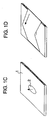
- a microporous membrane is cut out in a size of 60 mm in the longitudinal direction and 40 mm in the transverse direction, thereby obtaining a measurement sample.
- the sample is overspread over the glass plate 1 mounted with the drawing pin 2 so as to contact with the drawing pin in a vertical direction, and both ends of the membrane in the machine direction are fixed to the glass plate with a TEFLON (trademark) tape, thereby obtaining a measurement cell ( Fig. 1D ).
- the measurement cell was allowed to stand in an oven kept at a measurement temperature for 15 minutes, thereafter the sample was taken out, and then whether or not the pointed end of the drawing pin breaks through the membrane to cut a hole was observed. The highest temperature at which no hole is cut was taken as the break through temperature.
- the oven used for the measurement is ESPEC OVEN PH-101, manufactured by Tabai Espec Co.
- thermomechanical analysis TMA 120, manufactured by Seiko Instruments Inc.
- a maximum shrinkage load (g) was found from a shrinkage stress curve, and the maximum shrinkage stress was calculated by the following equation (2).
- Maximum shrinkage stress maximum shrinkage load / 3 ⁇ T ⁇ 100 ⁇ 9.807 ⁇ 10000 T: thickness of sample ( ⁇ m)
- the direction of the length of sample (10 mm) means the direction (longitudinal or transverse) intended to be measured.
- a microporous membrane is cut in a size of 120 mm x 120 mm, thereby obtaining a sample, and four marks are produced on the respective four corners at intervals of 100 mm in the longitudinal and transverse directions.
- the marked sample is sandwiched in pieces of paper and allowed to stand in an oven of 130°C for 60 minutes.
- a piece of paper is sandwiched between the samples, the entire assembly is further sandwiched in pieces of paper, and then the resultant is allowed to stand in an oven.
- the sample is taken out of the oven and cooled, and thereafter the length between the marks in the transverse direction is measured.
- the shrinking percentage is calculated by the following equation (3).
- Shrinking percentage % length in transverse direction before heating 100 mm ⁇ length in transverse direction after heating / length in transverse direction before heating 100 mm ⁇ 100
- the transverse direction means a direction vertical to a flow of a microporous membrane when the membrane is prepared by an extruder. If it is not known which direction of the sample is the machine direction (MD) or the transverse direction (TD) as of the time of production of the sample, it is acceptable that the measurement is carried out for both directions, and any one of the shrinking percentages is within a range of the preferred shrinking percentage as defined above.
- MD machine direction
- TD transverse direction
- the oven used for the measurement is ESPEC OVEN PH-101, manufactured by Tabai Espec Co.
- the intrinsic viscosity [ ⁇ ] in a decalin solvent at 135°C is measured according to ASTM D4020.
- a sample of a microporous membrane having a diameter ⁇ of 75 mm is dipped in ethanol to fill the pores with ethanol. Thereafter, pressure is applied thereto, and the pressure under which a bubble begins to develop from the membrane surface is read. The pressure value read is taken as the bubble point. Measurement temperature: 25 ⁇ 5°C.
- the membrane melting point was measured using DSC-220C, manufactured by Seiko Instruments Inc. A microporous membrane is cut into a circle having a diameter of 5 mm. Several sheets are placed one over the other until the weight becomes 3 mg, thereby obtaining a sample. The sample is spread on the entire surface of an aluminum open sample pan having a diameter of 5 mm, covered with a clamping cover and then fixed in the aluminum pan with the aid of a sample sealer. The measurement is carried out under a nitrogen atmosphere at temperatures from 30°C to 180°C at a temperature raising speed of 10°C/min. The temperature at which a melting endothermic curve has a maximal value is taken as the membrane melting point.
- Electrolytic solution a solution prepared by mixing propylene carbonate containing 1 mol/L lithium perchlorate (LiClO 4 ) with dimethoxyethane (50/50 vol%)
- FIG. 3A shows an organization of the measurement apparatus.
- Numerals 22a and 22b indicate a Ni foil having a thickness of 10 ⁇ m
- numerals 23a and 23b indicate a glass plate.
- Numeral 24 indicates an electrical resistance measuring apparatus (LCR meter, AG4311, manufactured by Ando Denki Co.), which is connected with the Ni foil (22a and 22b).
- Numeral 25 indicates a thermocouple, which is connected to a thermometer 26.
- Numeral 27 indicates a data collector, which is connected to the electrical resistance measuring apparatus 24 and the thermometer 26.
- Numeral 28 indicates an oven, in which the microporous membrane is heated.
- the microporous membrane 21 is impregnated with a prescribed electrolytic solution and, as shown in Fig. 3B , is fixed on the Ni foil 22a in such a manner that the membrane is held only in a longitudinal direction with the aid of a TEFLON (trademark) tape.
- the Ni foil 22b is masked with a TEFLON (trademark) tape, provided that a portion of 15 mm x 10 mm is freed from masking, as shown in Fig. 3C .
- the Ni foil 22a and the Ni foil 22b are placed one over the other in such a manner that the microporous membrane is sandwiched between them, and further said two Ni foils are sandwiched between glass plates 23a and 23b.
- a temperature and an electrical resistance are continuously measured.
- the temperature is increased at a speed of 2°C/min and the electrical resistance value is obtained at an alternating current of 1 kHz.
- a temperature at which the electrical resistance value of the microporous membrane 1 reaches 1000 ⁇ is defined to be the shutdown temperature.
- the temperature is further increased, and a temperature at which the shutdown membrane is ruptured and the electrical resistance value again reaches 1000 ⁇ is defined to be the membrane-rupture temperature.
- the prescribed electrolytic solution is as follows.
- the density of polyethylene is measured according to ASTM D1505.
- microporous membrane From the molded product, the DOP and pulverized silica were extraction-removed, thereby obtaining a microporous membrane. Two sheets of the microporous membrane were placed one over the other, stretched by 4.5 times in the machine direction at 110°C, thereafter stretched by 1.7 times in the transverse direction at 133°C, and finally heat-treated at 135°C. Physical properties of the thus-obtained microporous membrane are as shown in Tables 1 and 2.
- microporous membrane From the molded product, the DOP and pulverized silica were extraction-removed, thereby obtaining a microporous membrane. Two sheets of the microporous membrane were placed one over the other, stretched by 4.5 times in the machine direction at 110°C, thereafter stretched by 1.7 times in the transverse direction at 133°C, and finally heat-treated at 136°C. Physical properties of the thus-obtained microporous membrane are as shown in Tables 1 and 2.
- microporous membrane From the molded product, the DOP and pulverized silica were extraction-removed, thereby obtaining a microporous membrane. Two sheets of the microporous membrane were placed one over the other, stretched by 4.3 times in the machine direction at 110°C, thereafter stretched by 1.7 times in the transverse direction at 133°C, and finally heat-treated at 137°C. Physical properties of the thus-obtained microporous membrane are as shown in Tables 1 and 2.
- microporous membrane From the molded product, the DOP and pulverized silica were extraction-removed, thereby obtaining a microporous membrane. Two sheets of the microporous membrane were placed one over the other, stretched by 4.3 times in the machine direction at 110°C, thereafter stretched by 1.7 times in the transverse direction at 133°C, and finally heat-treated at 139°C. Physical properties of the thus-obtained microporous membrane are as shown in Tables 1 and 2.
- microporous membrane From the molded product, the DOP and pulverized silica were extraction-removed, thereby obtaining a microporous membrane. Two sheets of the microporous membrane were placed one over the other, stretched by 4.8 times in the machine direction at 115°C, thereafter stretched by 1.7 times in the transverse direction at 135°C, and finally heat-treated at 139°C. Physical properties of the thus-obtained microporous membrane are as shown in Tables 1 and 2.
- microporous membrane From the molded product, DOP and the pulverized silica were extraction-removed, thereby obtaining a microporous membrane. Two sheets of the microporous membrane were placed one over the other, stretched by 4.0 times in the machine direction at 110°C, thereafter stretched by 1.7 times in the transverse direction at 133°C, and finally heat-treated at 139°C. Physical properties of the thus-obtained microporous membrane are as shown in Tables 1 and 2.
- the DOP and pulverized silica were extraction-removed, thereby obtaining a microporous membrane.
- Two sheets of the microporous membrane were placed one over the other, stretched by 4.6 times in the machine direction at 115°C, thereafter stretched by 2 times in the transverse direction at 130°C, and finally heat-treated at 137°C.
- Physical properties of the microporous membrane thus-obtained are as shown in Tables 1 and 2.
- the DOP and pulverized silica were extraction-removed, thereby obtaining a microporous membrane.
- Two sheets of the microporous membrane were placed one over the other, stretched by 4.8 times in the machine direction at 115°C, thereafter stretched by 2.2 times in the transverse direction at 134°C, and finally heat-treated at 139°C.
- Physical properties of the microporous membrane thus-obtained are as shown in Tables 1 and 2.
- the DOP and pulverized silica were extraction-removed, thereby obtaining a microporous membrane.
- Two sheets of the microporous membrane were placed one over the other, stretched by 4.8 times in the machine direction at 115°C, thereafter stretched by 2.5 times in the transverse direction at 134°C, and finally heat-treated at 139°C Physical properties of the microporous membrane thus-obtained are as shown in Tables 1 and 2.
- the DOP and pulverized silica were extraction-removed, thereby obtaining a microporous membrane.
- Two sheets of the microporous membrane were placed one over the other, stretched by 4.5 times in the machine direction at 115°C, thereafter stretched by 2.1 times in the transverse direction at 120°C, and finally heat-treated at 137°C.
- Physical properties of the microporous membrane obtained are as shown in Tables 1 and 2.
- the DOP and pulverized silica were extraction-removed, thereby obtaining a microporous membrane.
- Two sheets of the microporous membrane were placed one over the other, stretched by 4.3 times in the machine direction at 115°C, thereafter stretched by 1.9 times in the transverse direction at 120°C, and finally heat-treated at 136°C.
- Physical properties of the microporous membrane thus-obtained are as shown in Tables 1 and 2.
- the DOP and pulverized silica were extraction-removed, thereby obtaining a microporous membrane.
- Two sheets of the microporous membrane were placed one over the other, stretched by 4.3 times in the machine direction at 115°C, thereafter stretched by 2 times in the transverse direction at 120°C, and finally heat-treated at 137°C.
- Physical properties of the microporous membrane thus-obtained are as shown in Tables 1 and 2.
- the DOP and pulverized silica were extraction-removed, thereby obtaining a microporous membrane.
- Two sheets of the microporous membrane were placed one over the other, stretched by 5 times in the machine direction at 115°C, thereafter stretched by 2.2 times in the transverse direction at 120°C, and finally heat-treated at 138°C.
- Physical properties of the microporous membrane thus-obtained are as shown in Tables 1 and 2.
- the DOP and pulverized silica were extraction-removed, thereby obtaining a microporous membrane.
- Two sheets of the microporous membrane were placed one over the other, stretched by 5.5 times in the machine direction at 115°C, thereafter stretched by 2.2 times in the transverse direction at 120°C, and finally heat-treated at 139°C.
- Physical properties of the microporous membrane thus-obtained are as shown in Tables 1 and 2.
- the DOP and pulverized silica were extraction-removed, thereby obtaining a microporous membrane.
- Two sheets of the microporous membrane were placed one over the other, stretched by 4.8 times in the machine direction at 115°C, thereafter stretched by 2 times in the transverse direction at 120°C, and finally heat-treated at 138°C.
- Physical properties of the microporous membrane thus-obtained are as shown in Tables 1 and 2.
- the granulated product was melt-kneaded in a twin screw extruder equipped with a T die at the leading edge, extruded therefrom, and then rolled from both sides with heated rolls, thereby obtaining a sheet like molded product having a thickness of 110 ⁇ m.
- the DOP and pulverized silica were extraction-removed, thereby obtaining a microporous membrane.
- Two sheets of the microporous membrane were placed one over the other, stretched by 4.8 times in the machine direction at 115°C, thereafter stretched by 2 times in the transverse direction at 120°C, and finally heat-treated at 135°C. Physical properties of the microporous membrane thus-obtained are as shown in Tables 1 and 2.
- the molded product was led to a simultaneous biaxial tenter stretching machine, in which a simultaneous biaxial stretching was carried out at 120°C with magnifying powers in the machine direction and in the transverse direction of 7.0 times and 6.1 times, respectively. Thereafter, the liquid paraffin was extraction-removed.
- the feeder and the pump were adjusted so as to make the liquid paraffin content in the extruded mixture as a whole 62 wt%. Thereafter, the extrusion product was passed through a T-die and rolled with cooling rolls controlled to a surface temperature of 30°C, thereby obtaining a sheet like molded product.
- the molded product was led to a simultaneous biaxial tenter stretching machine, in which a simultaneous biaxial stretching was carried out at 120°C with magnifying powers in the machine direction and in the transverse direction of 7.0 times and 6.1 times, respectively. Thereafter, the liquid paraffin was extraction-removed.
- the DOP and pulverized silica were extraction-removed, thereby obtaining a microporous membrane.
- Two sheets of the microporous membrane were placed one over the other, stretched by 4.4 times in the machine direction at 110°C, thereafter stretched by 1.7 times in the transverse direction at 133°C, and finally heat-treated at 135°C. Physical properties of the microporous membrane thus-obtained are as shown in Tables 1 and 2.
- the resulting microporous membrane has less strength, i.e., a piercing strength of 2.3 N/20 ⁇ m.
- the DOP and pulverized silica were extraction-removed, thereby obtaining a microporous membrane.
- Two sheets of the microporous membrane were placed one over the other and stretched by 4.0 times in the machine direction at 110°C. Physical properties of the microporous membrane obtained are as shown in Tables 1 and 2.
- the absence of stretching in the transverse direction after the stretching at a ratio of 4.0 in the machine direction resulted in a microporous membrane with increased gas transmission rate, i.e., 800 sec/100cc/20 ⁇ m.
- the DOP and pulverized silica were extraction-removed, thereby obtaining a microporous membrane.
- Two sheets of the microporous membrane were placed one over the other and stretched by 2.7 times in the machine direction at 110°C. Physical properties of the microporous membrane thus-obtained are as shown in Tables 1 and 2. Because of such a low magnifying power of stretching in the machine direction as 2.7 times, the resulting microporous membrane has low gas transmission rate. However, the strength is lowered to 1.7 N/20 ⁇ m in its piercing strength.
- a microporous membrane was obtained as in Comparative Example 3, except that the magnifying power of stretching in the machine direction was 3.7 times. Physical properties of the microporous membrane obtained are as shown in Tables 1 and 2. Because the magnifying power of stretching in the machine direction was increased to 3.7 times, the piercing strength reached 2.5 N/20 ⁇ m. However, since stretching was carried out in the machine direction only, the polymer was highly oriented in the machine direction, so that the resulting microporous membrane was lowered in its break through temperature.
- the granulated product was melt-kneaded in a twin screw extruder equipped with a T die at the leading edge, extruded therefrom, and then rolled from both sides with heated rolls, thereby obtaining a sheet like molded product having a thickness of 110 ⁇ m.
- the DOP and pulverized silica were extraction-removed, thereby obtaining a microporous membrane.
- Two sheets of the microporous membrane were placed one over the other, stretched by 4.3 times in the machine direction at 117°C, thereafter stretched by 1.9 times in the transverse direction at 120°C, and finally heat-treated at 130°C. Physical properties of the microporous membrane obtained are as shown in Tables 1 and 2.
- the membrane melting point of the membrane stretched in the machine direction is found to be as low as 130°C, it is impossible to increase the transverse stretching temperature and the heat-treatment temperature to 130°C or higher. As a result, the microporous membrane has high maximum shrinkage stress and a high shrinking percentage.
- Example 1 3.6 284 142 155 137 135 0.9
- Example 2 4.0 294 142 155 138 136 0.9
- Example 3 4.7 324 143 155 138 136 0.8
- Example 4 6.0 373 143 155 139 137 0.9
- Example 5 6.2 373 144 153 139 137 0.9
- Example 6 7.5 275 144 155 139 137 0.9
- Example 7 6.2 392 144 153 139 138 1.1
- Example 8 6.2 392 145 153 139 138 1.2
- Example 9 6.2 392 145 153 139 138 1.2
- Example 10 4.9 402 145 156 139 138 1.1
- Example 11 4.8 392 143 155 139 138 1.1
- Example 12 4.8 363 144 156 139 137 1.3
- Example 13 4.8 382 145 156
- the polyolefin microporous membrane in accordance with the present invention is low in gas transmission, superior in permeability and superior in membrane strength and safety under a high temperature condition, and is particularly useful as a separator for a non-aqueous electrolytic solution type battery.
Landscapes
- Chemical & Material Sciences (AREA)
- Chemical Kinetics & Catalysis (AREA)
- Engineering & Computer Science (AREA)
- Electrochemistry (AREA)
- General Chemical & Material Sciences (AREA)
- Manufacturing & Machinery (AREA)
- Medicinal Chemistry (AREA)
- Materials Engineering (AREA)
- Health & Medical Sciences (AREA)
- Polymers & Plastics (AREA)
- Organic Chemistry (AREA)
- Inorganic Chemistry (AREA)
- Manufacture Of Porous Articles, And Recovery And Treatment Of Waste Products (AREA)
- Cell Separators (AREA)
Claims (9)
- Mikroporöse Polyolefinmembran, die eine Membrandicke von 5 bis 24 µm, einen Hohlraumgehalt von 40 bis 60%, eine Gasdurchlässigkeit von 40 bis 300 s/100 cm3/20 µm, eine Durchstechfestigkeit von nicht weniger als 2,5 N/20 µm und eine Durchbruchtemperatur von nicht weniger als 110 °C aufweist und eine Grenzviskositätszahl [η] von 3,5 bis 8 dl/g aufweist, wobei die Grenzviskositätszahl [η] in einem Decalin-Lösungsmittel bei 135 °C gemäß ASTM D4020 gemessen wird.
- Mikroporöse Polyolefinmembran gemäß Anspruch 1, die eine maximale Schrumpfungsspannung in Querrichtung von nicht mehr als 363 kPa und/oder eine prozentuale Schrumpfung bei 130 °C in Querrichtung von nicht mehr als 25% aufweist.
- Mikroporöse Polyolefinmembran gemäß Anspruch 1 oder 2, die einen Blaspunkt (Bubble Point) von 196 bis 490 kPa und eine Abschalttemperatur von 138 bis 150 °C aufweist.
- Mikroporöse Polyolefinmembran gemäß einem der Ansprüche 1 bis 3, die eine Membrandicke von 5 bis 22 µm, einen Hohlraumgehalt von 40 bis 60%, eine Gasdurchlässigkeit von 40 bis 260 s/100 cm3/20 µm und eine Durchstechfestigkeit von nicht weniger als 2,8 N/20 µm aufweist.
- Mikroporöse Polyolefinmembran gemäß einem der Ansprüche 1 bis 3, die eine Durchbruchtemperatur von nicht weniger als 115 °C aufweist.
- Mikroporöse Polyolefinmembran gemäß einem der Ansprüche 1 bis 5, die eine Membrandicke von 5 bis 20 µm, einen Hohlraumgehalt von 40 bis 60%, eine Gasdurchlässigkeit von 40 bis 200 s/100 cm3/20 µm, eine Durchstechfestigkeit von nicht weniger als 3,0 N/20 µm und eine Durchbruchtemperatur von nicht weniger als 120 °C aufweist.
- Mikroporöse Polyolefinmembran gemäß einem der Ansprüche 1 bis 6, die nach einem Verfahren erhalten ist, bei dem eine Zusammensetzung, die wenigstens ein Polyolefin, ein organisches flüssiges Material und/oder Siliciumoxid umfasst, und ein Additiv verwendet wird und das die folgenden Schritte (a) bis (f) umfasst:(a) einen Schritt des Mischens eines Polyolefins, eines organischen flüssigen Materials und/oder Siliciumoxid und eines Additivs in einem Henschel-Mischer oder dergleichen zur Durchführung einer Granulierung;(b) einen Schritt des Schmelzknetens des in Schritt (a) erhaltenen Gemischs in einem Extruder, der an seinem Vorderrand mit einer Breitschlitzdüse ausgestattet ist;(c) einen Schritt des Extrudierens des in Schritt (b) erhaltenen gekneteten Produkts aus der Breitschlitzdüse, beidseitiges Walzen desselben mit beheizten Walzen und danach Abkühlen des resultierenden Produkts, um es zu einer Folie zu formen;(d) einen Schritt des Extrahierens/Entfernens des organischen flüssigen Materials und/oder des Siliciumoxids aus dem in Schritt (c) erhaltenen folienartigen geformten Produkt, wodurch man eine unverstreckte mikroporöse Membran erhält;(e) einen Schritt des Streckens der in Schritt (d) erhaltenen unverstreckten mikroporösen Membran auf wenigstens das Dreifache in Maschinenrichtung; und(f) einen Schritt des Durchführens des Streckens in Querrichtung im Anschluss an Schritt (e) und danach Wärmebehandeln des resultierenden Produkts bei einer Temperatur, die höher ist als die Strecktemperatur.
- Mikroporöse Polyolefinmembran gemäß einem der Ansprüche 1 bis 7, die ein Gemisch aus einem Polyethylen mit ultrahohem Molekulargewicht mit einer Grenzviskositätszahl [η] von 5 bis 20 dl/g in einer Menge von 10 bis 90 Gew.-% und einem Polyethylen mit hohem Molekulargewicht mit einer Grenzviskositätszahl [η] von 1,5 bis 4 dl/g und einer Dichte von mehr als 0,94 g/cm3 in einer Menge von 10 bis 90 Gew.-% umfasst.
- Separator für Batterien des Typs mit nichtwässriger Elektrolytlösung, umfassend die mikroporöse Polyolefinmembran gemäß einem der Ansprüche 1 bis 8.
Applications Claiming Priority (5)
| Application Number | Priority Date | Filing Date | Title |
|---|---|---|---|
| JP2002248913 | 2002-08-28 | ||
| JP2002248913 | 2002-08-28 | ||
| JP2002372353 | 2002-12-24 | ||
| JP2002372353 | 2002-12-24 | ||
| PCT/JP2003/010771 WO2004020511A1 (ja) | 2002-08-28 | 2003-08-26 | ポリオレフィン製微多孔膜及びその評価方法 |
Publications (3)
| Publication Number | Publication Date |
|---|---|
| EP1464669A1 EP1464669A1 (de) | 2004-10-06 |
| EP1464669A4 EP1464669A4 (de) | 2005-04-20 |
| EP1464669B1 true EP1464669B1 (de) | 2016-11-30 |
Family
ID=31980500
Family Applications (1)
| Application Number | Title | Priority Date | Filing Date |
|---|---|---|---|
| EP03791293.8A Expired - Lifetime EP1464669B1 (de) | 2002-08-28 | 2003-08-26 | Mikroporöse polyolefinmembran |
Country Status (8)
| Country | Link |
|---|---|
| US (1) | US7374843B2 (de) |
| EP (1) | EP1464669B1 (de) |
| JP (2) | JP4780960B2 (de) |
| KR (1) | KR100599898B1 (de) |
| CN (1) | CN100564433C (de) |
| AU (1) | AU2003257544A1 (de) |
| TW (1) | TW200417564A (de) |
| WO (1) | WO2004020511A1 (de) |
Families Citing this family (57)
| Publication number | Priority date | Publication date | Assignee | Title |
|---|---|---|---|---|
| JP2004303475A (ja) * | 2003-03-28 | 2004-10-28 | Sanyo Electric Co Ltd | 非水電解質電池 |
| CN101014649B (zh) * | 2004-08-30 | 2010-06-23 | 旭化成电子材料株式会社 | 聚烯烃微多孔膜和蓄电池用隔离体 |
| CN101031421B (zh) * | 2004-10-01 | 2011-07-27 | 旭化成电子材料株式会社 | 聚烯烃微孔膜 |
| KR100943235B1 (ko) * | 2005-05-16 | 2010-02-18 | 에스케이에너지 주식회사 | 압출혼련성과 물성이 우수한 고밀도폴리에틸렌 미세다공막및 그 제조방법 |
| WO2007069560A1 (ja) * | 2005-12-15 | 2007-06-21 | Asahi Kasei Chemicals Corporation | ポリオレフィン製微多孔膜 |
| US8017263B2 (en) * | 2006-01-24 | 2011-09-13 | Sony Corporation | Separator and battery |
| US10615388B2 (en) * | 2006-03-22 | 2020-04-07 | Celgard, Llc | Membrane made of a blend of UHMW polyolefins |
| CN101375436B (zh) * | 2006-05-22 | 2010-10-06 | 松下电器产业株式会社 | 隔膜及非水电解质二次电池 |
| JP5288736B2 (ja) * | 2006-07-13 | 2013-09-11 | 旭化成イーマテリアルズ株式会社 | セラミック複合体 |
| EP2065432B2 (de) | 2006-09-20 | 2017-10-25 | Asahi Kasei Kabushiki Kaisha | Mikroporöse polyolefinmembran und separator für batterie mit nichtwässrigem elektrolyt |
| JPWO2008059806A1 (ja) * | 2006-11-14 | 2010-03-04 | 旭化成イーマテリアルズ株式会社 | リチウムイオン二次電池用セパレータ及びその製造方法 |
| WO2008069216A1 (ja) * | 2006-12-04 | 2008-06-12 | Asahi Kasei Chemicals Corporation | ポリオレフィン製微多孔膜 |
| JP4753446B2 (ja) * | 2007-01-30 | 2011-08-24 | 旭化成イーマテリアルズ株式会社 | ポリオレフィン製微多孔膜 |
| PL2116372T3 (pl) | 2007-01-30 | 2018-08-31 | Asahi Kasei Kabushiki Kaisha | Wielowarstwowa porowata membrana i sposób jej wytwarzania |
| KR100858720B1 (ko) * | 2007-05-04 | 2008-09-17 | 김호 | 축전지용 격리판의 제조방법 |
| KR101432146B1 (ko) | 2007-11-28 | 2014-08-28 | 에스케이이노베이션 주식회사 | 물성과 고온 열안정성이 우수한 폴리올레핀 미세다공막 |
| WO2009136648A1 (ja) * | 2008-05-09 | 2009-11-12 | 旭化成イーマテリアルズ株式会社 | 高出力密度リチウムイオン二次電池用セパレータ |
| KR101640777B1 (ko) | 2008-11-17 | 2016-07-19 | 도레이 배터리 세퍼레이터 필름 주식회사 | 미세다공성 막, 이러한 막의 제조방법 및 사용방법 |
| CN101747549B (zh) * | 2008-12-18 | 2013-06-19 | 比亚迪股份有限公司 | 一种聚烯烃微多孔膜及其制备方法 |
| JP5295834B2 (ja) * | 2009-03-26 | 2013-09-18 | 旭化成イーマテリアルズ株式会社 | 合金系負極電極リチウムイオン二次電池用セパレーター |
| JP5189048B2 (ja) * | 2009-08-07 | 2013-04-24 | 旭化成イーマテリアルズ株式会社 | 捲回体 |
| FR2954595B1 (fr) * | 2009-12-21 | 2012-03-30 | Bollore | Film de separateur, son procede de fabrication, supercondensateur, batterie et condensateur munis du fim |
| CN101781417B (zh) * | 2010-02-10 | 2012-05-30 | 沧州明珠塑料股份有限公司 | 一种湿法制备聚烯烃微孔膜的方法 |
| KR101336593B1 (ko) | 2010-04-20 | 2013-12-05 | 에스케이이노베이션 주식회사 | 생산성이 우수하며 물성조절이 용이한 폴리올레핀계 미세다공막 제조방법 |
| JP5219099B2 (ja) * | 2010-06-14 | 2013-06-26 | 平松産業株式会社 | 電池用セパレータ材料、電池用セパレータの製造方法、電池用セパレータ、及び二次電池 |
| CN102134342B (zh) * | 2010-12-07 | 2013-01-02 | 杭州福膜新材料科技有限公司 | 一种交联型聚烯烃微孔膜及其制备方法 |
| KR101271299B1 (ko) | 2011-01-27 | 2013-06-04 | 미쓰비시 쥬시 가부시끼가이샤 | 폴리올레핀 수지 다공성 필름, 및 그것을 사용한 비수 전해질 전지용 세퍼레이터 |
| US20130228529A1 (en) * | 2011-11-04 | 2013-09-05 | Ppg Industries Ohio, Inc. | Microporous material having filtration and adsorption properties and their use in fluid purification processes |
| DE112011105835B4 (de) * | 2011-11-10 | 2020-01-23 | Toyota Jidosha Kabushiki Kaisha | Batterie |
| US9627672B2 (en) * | 2012-03-28 | 2017-04-18 | Asahi Kasei E-Materials Corporation | Separator for nonaqueous electrolyte batteries containing a porous membrane |
| WO2013165151A1 (ko) | 2012-04-30 | 2013-11-07 | 주식회사 엘지화학 | 세퍼레이터 및 이를 구비한 전기화학소자 |
| SG11201506733RA (en) * | 2013-02-27 | 2015-09-29 | Toray Battery Separator Film | Porous polyolefin film, battery separator obtained using same, and processes for producing these |
| EP2990198B1 (de) * | 2013-04-22 | 2018-09-05 | Toray Industries, Inc. | Laminierte poröse membran, verfahren zur herstellung davon und separator für eine batterie |
| HUE051724T2 (hu) | 2013-10-03 | 2021-03-29 | Toray Industries | Poliolefin porózus film, akkumulátor szeparátor, mely a porózus film alkalmazásával van elõállítva, és eljárás a porózus film és a szeparátor elõállítására |
| WO2015194504A1 (ja) * | 2014-06-20 | 2015-12-23 | 東レバッテリーセパレータフィルム株式会社 | ポリオレフィン微多孔質膜、電池用セパレータ及び電池 |
| JP6434732B2 (ja) * | 2014-07-24 | 2018-12-05 | 株式会社アストム | イオン交換膜の製造方法 |
| JP6202062B2 (ja) * | 2014-09-30 | 2017-09-27 | 住友化学株式会社 | 偏光フィルムの強度測定方法及び偏光板 |
| JP6548430B2 (ja) * | 2015-03-31 | 2019-07-24 | 旭化成株式会社 | ポリオレフィン微多孔膜の製造方法、電池用セパレータ、及び非水電解液二次電池 |
| CN105043958B (zh) * | 2015-07-09 | 2017-11-03 | 新乡市中科科技有限公司 | 一种微孔膜孔隙率的测试方法 |
| JP6975525B2 (ja) * | 2015-10-02 | 2021-12-01 | 株式会社日本触媒 | リチウムイオン二次電池 |
| CN105445313A (zh) * | 2015-11-30 | 2016-03-30 | 深圳市星源材质科技股份有限公司 | 一种电池隔膜的热稳定性检测方法 |
| KR102753394B1 (ko) * | 2017-02-02 | 2025-01-10 | 삼성전자주식회사 | 온도 감지 장치 및 이를 구비한 전자 장치 |
| CN110114211A (zh) * | 2017-02-23 | 2019-08-09 | 东丽株式会社 | 多孔性膜、二次电池用隔膜及二次电池 |
| KR102264032B1 (ko) | 2017-03-27 | 2021-06-11 | 아사히 가세이 가부시키가이샤 | 폴리올레핀 미다공막 및 폴리올레핀 미다공막의 제조 방법 |
| TW201940528A (zh) | 2018-02-23 | 2019-10-16 | 日商東麗股份有限公司 | 多孔性聚烯烴薄膜 |
| ES2971108T3 (es) | 2018-03-28 | 2024-06-03 | Lg Energy Solution Ltd | Método para evaluar la estabilidad de un separador |
| JP6517404B2 (ja) * | 2018-06-04 | 2019-05-22 | 株式会社アストム | イオン交換膜 |
| DE102018131928A1 (de) * | 2018-12-12 | 2020-06-18 | Carl Freudenberg Kg | Separator für elektrochemische Energiespeicher und Wandler |
| JP2020171923A (ja) * | 2019-04-11 | 2020-10-22 | 旭化成株式会社 | 多孔質膜 |
| JP7215955B2 (ja) * | 2019-04-16 | 2023-01-31 | 住友化学株式会社 | 非水電解液二次電池用多孔質層 |
| CN114207004B (zh) | 2019-08-22 | 2023-04-25 | 东丽株式会社 | 聚烯烃微多孔膜、电池用隔膜和二次电池 |
| CN111272554B (zh) * | 2020-03-27 | 2023-07-11 | 九江德福科技股份有限公司 | 一种铜箔泡泡纱的定量分析方法 |
| US12379298B2 (en) | 2020-07-08 | 2025-08-05 | Lg Energy Solution, Ltd. | Defective porous sheet detection system and detection method |
| EP4001348A1 (de) * | 2020-11-20 | 2022-05-25 | Toray Industries, Inc. | Mikroporöse polyolefinmembran, batterieseparator und sekundärbatterie |
| JPWO2023176876A1 (de) | 2022-03-18 | 2023-09-21 | ||
| WO2024193835A1 (en) | 2022-11-07 | 2024-09-26 | Basell Poliolefine Italia S.R.L. | Polypropylene resin compositon |
| WO2024193834A1 (en) | 2022-11-07 | 2024-09-26 | Basell Poliolefine Italia S.R.L. | Polypropylene resin compositon |
Family Cites Families (25)
| Publication number | Priority date | Publication date | Assignee | Title |
|---|---|---|---|---|
| JPH0221559A (ja) | 1988-07-08 | 1990-01-24 | Nitto Denko Corp | 電池用セパレータとその製造法 |
| JP2794179B2 (ja) | 1988-09-30 | 1998-09-03 | 旭化成工業株式会社 | ポリエチレン微多孔膜及びリチウム電池セパレーター |
| JP2952017B2 (ja) | 1990-09-18 | 1999-09-20 | 日東電工株式会社 | 電池用セパレータ、その製造法および電池 |
| CA2078324C (en) * | 1991-07-05 | 1997-09-23 | Hiroshi Sogo | Separator for a battery using an organic electrolytic solution and method for producing the same |
| JP3305006B2 (ja) | 1991-07-05 | 2002-07-22 | 旭化成株式会社 | 有機電解液を用いる電池用セパレータ及びその製造方法 |
| JP3121047B2 (ja) | 1991-07-08 | 2000-12-25 | 旭化成工業株式会社 | 均質なポリエチレン製微多孔膜及びその製造方法 |
| JP2657434B2 (ja) | 1991-07-19 | 1997-09-24 | 東燃株式会社 | ポリエチレン微多孔膜、その製造方法及びそれを用いた電池用セパレータ |
| DE69229170T2 (de) | 1991-12-27 | 1999-10-14 | Mitsui Chemicals | Zweiachsig orientierter hochmolekularer polyethylenfilm und oberflächenmodifizierter zweiachsig orientierter hochmolekularer polyethylenfilm sowie deren herstellung |
| JP2896267B2 (ja) | 1992-05-21 | 1999-05-31 | 三井化学株式会社 | 高分子量ポリエチレン配向フィルムとその製造方法 |
| JP3003830B2 (ja) | 1994-05-12 | 2000-01-31 | 宇部興産株式会社 | 積層多孔質フイルム及びその製法 |
| JP3497569B2 (ja) | 1994-08-17 | 2004-02-16 | 旭化成ケミカルズ株式会社 | 非水系電池セパレーター用ポリエチレン製微多孔膜 |
| JP3444712B2 (ja) | 1996-02-16 | 2003-09-08 | 旭化成株式会社 | 電池セパレーターに適した微多孔膜 |
| TW431962B (en) | 1996-11-19 | 2001-05-01 | Mitsui Chemicals Inc | Porpus film of high molecular wight polyolefin and process for producing same |
| JPH1121370A (ja) | 1997-07-07 | 1999-01-26 | Mitsubishi Chem Corp | ポリエチレン樹脂製多孔性フィルム |
| JP4098401B2 (ja) * | 1998-05-19 | 2008-06-11 | 旭化成ケミカルズ株式会社 | ポリオレフィン製の電池セパレーター用微多孔膜 |
| JP2000017100A (ja) * | 1998-07-03 | 2000-01-18 | Asahi Chem Ind Co Ltd | ポリエチレン微多孔膜の製造方法 |
| JP4209986B2 (ja) | 1999-01-22 | 2009-01-14 | 旭化成ケミカルズ株式会社 | ポリオレフィン系微多孔膜二次電池用セパレータ |
| JP4460668B2 (ja) * | 1999-03-03 | 2010-05-12 | 東燃化学株式会社 | ポリオレフィン微多孔膜及びその製造方法 |
| JP4177929B2 (ja) | 1999-03-04 | 2008-11-05 | 日東電工株式会社 | 多孔質フィルム及びその製造方法 |
| WO2000068305A1 (fr) * | 1999-05-07 | 2000-11-16 | Nitto Denko Corporation | Films poreux et leurs procedes d'obtention |
| JP4606532B2 (ja) * | 1999-09-17 | 2011-01-05 | 旭化成イーマテリアルズ株式会社 | ポリオレフィン製微多孔膜 |
| TWI315591B (en) * | 2000-06-14 | 2009-10-01 | Sumitomo Chemical Co | Porous film and separator for battery using the same |
| CN1210823C (zh) * | 2000-11-01 | 2005-07-13 | 东洋纺织株式会社 | 蓄电池隔板及其制造方法 |
| JP2002284918A (ja) * | 2001-03-23 | 2002-10-03 | Tonen Chem Corp | ポリオレフィン微多孔膜及びその製造方法並びに用途 |
| JP2003119306A (ja) | 2001-10-11 | 2003-04-23 | Nitto Denko Corp | 低収縮性微多孔膜およびその製法 |
-
2003
- 2003-08-26 US US10/493,834 patent/US7374843B2/en not_active Expired - Lifetime
- 2003-08-26 JP JP2004532709A patent/JP4780960B2/ja not_active Expired - Fee Related
- 2003-08-26 KR KR1020047007594A patent/KR100599898B1/ko not_active Expired - Fee Related
- 2003-08-26 CN CNB038014203A patent/CN100564433C/zh not_active Expired - Lifetime
- 2003-08-26 WO PCT/JP2003/010771 patent/WO2004020511A1/ja not_active Ceased
- 2003-08-26 EP EP03791293.8A patent/EP1464669B1/de not_active Expired - Lifetime
- 2003-08-26 AU AU2003257544A patent/AU2003257544A1/en not_active Abandoned
- 2003-08-27 TW TW92123647A patent/TW200417564A/zh unknown
-
2008
- 2008-11-26 JP JP2008300387A patent/JP4931894B2/ja not_active Expired - Lifetime
Non-Patent Citations (1)
| Title |
|---|
| None * |
Also Published As
| Publication number | Publication date |
|---|---|
| WO2004020511A1 (ja) | 2004-03-11 |
| US7374843B2 (en) | 2008-05-20 |
| KR20050039745A (ko) | 2005-04-29 |
| EP1464669A1 (de) | 2004-10-06 |
| EP1464669A4 (de) | 2005-04-20 |
| AU2003257544A1 (en) | 2004-03-19 |
| JP4780960B2 (ja) | 2011-09-28 |
| KR100599898B1 (ko) | 2006-07-19 |
| CN100564433C (zh) | 2009-12-02 |
| US20050019665A1 (en) | 2005-01-27 |
| JPWO2004020511A1 (ja) | 2005-12-15 |
| TW200417564A (en) | 2004-09-16 |
| CN1578806A (zh) | 2005-02-09 |
| JP4931894B2 (ja) | 2012-05-16 |
| JP2009108323A (ja) | 2009-05-21 |
Similar Documents
| Publication | Publication Date | Title |
|---|---|---|
| EP1464669B1 (de) | Mikroporöse polyolefinmembran | |
| EP2108675B1 (de) | Mikroporöse polyolefinmembran | |
| EP2586609B2 (de) | Mikroporöses Material und Herstellungsverfahren dafür | |
| EP2261276B1 (de) | Mikroporöse polyolefinmembran und wicklungsprodukte | |
| KR101723275B1 (ko) | 폴리올레핀제 미다공막 | |
| EP2065432B1 (de) | Mikroporöse polyolefinmembran und separator für batterie mit nichtwässrigem elektrolyt | |
| JP4931163B2 (ja) | ポリオレフィン製微多孔膜 | |
| US6949315B1 (en) | Shutdown separators with improved properties | |
| EP3438177A1 (de) | Mikroporöse polyolefinmembran, herstellungsverfahren für mikroporöse polyolefinmembran, batterieseparator und batterie | |
| JP4098401B2 (ja) | ポリオレフィン製の電池セパレーター用微多孔膜 | |
| JP5572334B2 (ja) | ポリオレフィン製微多孔膜 | |
| EP1956041B1 (de) | Mikroporöse polyolefinmembran, herstellungsverfahren dafür, separator für zelle und zelle | |
| JP2010202828A (ja) | ポリオレフィン製微多孔膜 | |
| EP1956040B1 (de) | Mikroporöse polyolefinmembran, herstellungsverfahren dafür, separator für eine zelle und zelle | |
| JP2011063025A (ja) | ポリオレフィン製微多孔膜 | |
| JP2000204188A (ja) | ポリエチレン微多孔膜 | |
| US7323274B1 (en) | Shutdown separators with improved properties | |
| US7662518B1 (en) | Shutdown separators with improved properties | |
| JP4964565B2 (ja) | ポリエチレン製微多孔膜 | |
| JPH11140209A (ja) | 多孔質フィルム、非水電解液電池用セパレータ及び非水電解液電池 |
Legal Events
| Date | Code | Title | Description |
|---|---|---|---|
| PUAI | Public reference made under article 153(3) epc to a published international application that has entered the european phase |
Free format text: ORIGINAL CODE: 0009012 |
|
| 17P | Request for examination filed |
Effective date: 20040415 |
|
| AK | Designated contracting states |
Kind code of ref document: A1 Designated state(s): AT BE BG CH CY CZ DE DK EE ES FI FR GB GR HU IE IT LI LU MC NL PT RO SE SI SK TR |
|
| AX | Request for extension of the european patent |
Extension state: AL LT LV MK |
|
| A4 | Supplementary search report drawn up and despatched |
Effective date: 20050304 |
|
| DAX | Request for extension of the european patent (deleted) | ||
| RBV | Designated contracting states (corrected) |
Designated state(s): DE FR GB IT |
|
| 17Q | First examination report despatched |
Effective date: 20070118 |
|
| GRAP | Despatch of communication of intention to grant a patent |
Free format text: ORIGINAL CODE: EPIDOSNIGR1 |
|
| RIC1 | Information provided on ipc code assigned before grant |
Ipc: C08J 9/26 20060101AFI20160601BHEP Ipc: H01M 2/16 20060101ALI20160601BHEP Ipc: B01D 71/26 20060101ALI20160601BHEP Ipc: B01D 67/00 20060101ALI20160601BHEP Ipc: B01D 69/02 20060101ALI20160601BHEP Ipc: B01D 65/10 20060101ALI20160601BHEP Ipc: H01M 2/14 20060101ALI20160601BHEP |
|
| INTG | Intention to grant announced |
Effective date: 20160628 |
|
| GRAS | Grant fee paid |
Free format text: ORIGINAL CODE: EPIDOSNIGR3 |
|
| GRAA | (expected) grant |
Free format text: ORIGINAL CODE: 0009210 |
|
| RAP1 | Party data changed (applicant data changed or rights of an application transferred) |
Owner name: ASAHI KASEI KABUSHIKI KAISHA |
|
| AK | Designated contracting states |
Kind code of ref document: B1 Designated state(s): DE FR GB IT |
|
| REG | Reference to a national code |
Ref country code: GB Ref legal event code: FG4D |
|
| REG | Reference to a national code |
Ref country code: DE Ref legal event code: R096 Ref document number: 60349669 Country of ref document: DE |
|
| REG | Reference to a national code |
Ref country code: FR Ref legal event code: PLFP Year of fee payment: 15 |
|
| PG25 | Lapsed in a contracting state [announced via postgrant information from national office to epo] |
Ref country code: IT Free format text: LAPSE BECAUSE OF FAILURE TO SUBMIT A TRANSLATION OF THE DESCRIPTION OR TO PAY THE FEE WITHIN THE PRESCRIBED TIME-LIMIT Effective date: 20161130 |
|
| REG | Reference to a national code |
Ref country code: DE Ref legal event code: R097 Ref document number: 60349669 Country of ref document: DE |
|
| PLBE | No opposition filed within time limit |
Free format text: ORIGINAL CODE: 0009261 |
|
| STAA | Information on the status of an ep patent application or granted ep patent |
Free format text: STATUS: NO OPPOSITION FILED WITHIN TIME LIMIT |
|
| 26N | No opposition filed |
Effective date: 20170831 |
|
| REG | Reference to a national code |
Ref country code: FR Ref legal event code: PLFP Year of fee payment: 16 |
|
| PGFP | Annual fee paid to national office [announced via postgrant information from national office to epo] |
Ref country code: GB Payment date: 20220707 Year of fee payment: 20 Ref country code: DE Payment date: 20220705 Year of fee payment: 20 |
|
| PGFP | Annual fee paid to national office [announced via postgrant information from national office to epo] |
Ref country code: FR Payment date: 20220709 Year of fee payment: 20 |
|
| P01 | Opt-out of the competence of the unified patent court (upc) registered |
Effective date: 20230515 |
|
| REG | Reference to a national code |
Ref country code: DE Ref legal event code: R071 Ref document number: 60349669 Country of ref document: DE |
|
| REG | Reference to a national code |
Ref country code: GB Ref legal event code: PE20 Expiry date: 20230825 |
|
| PG25 | Lapsed in a contracting state [announced via postgrant information from national office to epo] |
Ref country code: GB Free format text: LAPSE BECAUSE OF EXPIRATION OF PROTECTION Effective date: 20230825 |