EP1464748A2 - Verfahren und Vorrichtung zum Beschicken von Strümpfen zur Transporteinrichtung einer Nähmaschine - Google Patents
Verfahren und Vorrichtung zum Beschicken von Strümpfen zur Transporteinrichtung einer Nähmaschine Download PDFInfo
- Publication number
- EP1464748A2 EP1464748A2 EP04007783A EP04007783A EP1464748A2 EP 1464748 A2 EP1464748 A2 EP 1464748A2 EP 04007783 A EP04007783 A EP 04007783A EP 04007783 A EP04007783 A EP 04007783A EP 1464748 A2 EP1464748 A2 EP 1464748A2
- Authority
- EP
- European Patent Office
- Prior art keywords
- stocking
- tip
- open tip
- assembly
- open
- Prior art date
- Legal status (The legal status is an assumption and is not a legal conclusion. Google has not performed a legal analysis and makes no representation as to the accuracy of the status listed.)
- Withdrawn
Links
- 238000009958 sewing Methods 0.000 title claims abstract description 28
- 238000000034 method Methods 0.000 title claims description 16
- 238000007664 blowing Methods 0.000 claims description 8
- 238000003780 insertion Methods 0.000 claims description 5
- 230000037431 insertion Effects 0.000 claims description 5
- 239000000725 suspension Substances 0.000 claims description 4
- 230000015572 biosynthetic process Effects 0.000 claims 3
- 210000000080 chela (arthropods) Anatomy 0.000 claims 1
- 230000000712 assembly Effects 0.000 abstract description 3
- 238000000429 assembly Methods 0.000 abstract description 3
- 239000012530 fluid Substances 0.000 description 7
- 238000006073 displacement reaction Methods 0.000 description 5
- 238000004519 manufacturing process Methods 0.000 description 4
- 238000002360 preparation method Methods 0.000 description 4
- 238000009825 accumulation Methods 0.000 description 2
- 230000004913 activation Effects 0.000 description 2
- 238000012546 transfer Methods 0.000 description 2
- 238000009941 weaving Methods 0.000 description 2
- 238000013459 approach Methods 0.000 description 1
- 230000005540 biological transmission Effects 0.000 description 1
- 238000010276 construction Methods 0.000 description 1
- 238000005520 cutting process Methods 0.000 description 1
- 230000000694 effects Effects 0.000 description 1
- 239000004744 fabric Substances 0.000 description 1
- 230000010355 oscillation Effects 0.000 description 1
- 229920000728 polyester Polymers 0.000 description 1
- 230000033764 rhythmic process Effects 0.000 description 1
- 238000000926 separation method Methods 0.000 description 1
- 230000001360 synchronised effect Effects 0.000 description 1
- 238000013519 translation Methods 0.000 description 1
Images




Classifications
-
- D—TEXTILES; PAPER
- D05—SEWING; EMBROIDERING; TUFTING
- D05B—SEWING
- D05B23/00—Sewing apparatus or machines not otherwise provided for
- D05B23/007—Sewing units for assembling parts of knitted panties or closing the stocking toe part
- D05B23/009—Toe closers
-
- D—TEXTILES; PAPER
- D05—SEWING; EMBROIDERING; TUFTING
- D05B—SEWING
- D05B23/00—Sewing apparatus or machines not otherwise provided for
- D05B23/007—Sewing units for assembling parts of knitted panties or closing the stocking toe part
Definitions
- the present invention relates, in general, to the production of stockings on circular stocking machines.
- each stocking, with its tip open is transferred to an accumulation container and thence to a sewing machine for the sewing of the tip.
- the sewing machine is traditionally provided with a conveyor assembly including a pair of horizontal bars which delimit a longitudinal guiding slit for the insertion of the open tip of the stocking after it has preventively been flattened at the tapers of the tip.
- the object of the present invention is to provide a method and a device which allow to make at least semi-automated the operations of loading the stockings onto the conveyor of the sewing machine, thereby speeding up said operation, freeing it from the limits connected to the manual operations heretofore required.
- said object is achieved thanks to a method for loading a stocking onto the conveyor of a sewing machine, whose primary characteristic is that it entails a preliminary operation of preparing the open tip of the stocking, consisting of forming a thread bridge joined at its end at two opposite areas of the open tip of the stocking corresponding to the end of the related tapers and extending through said open tip for a length that is substantially equal to the width of the tip when the tip is flattened.
- the aforesaid thread bridge which according to the invention is conveniently made by the circular stocking machine in the final phase of manufacture of the open tip of the stocking, allows to manipulate in mechanical fashion, i.e. with no need for manual intervention, the stocking during its loading onto the conveyor of the sewing machine.
- the manufacture of the open tip of the stocking entails, at the end of the tapering of the tip, forming a complete rank with the same yarn as the stocking but woven with thicker stitches and reinforced with the addition of a second thread, forming another complete rank with the same yarn as the stocking but woven with loose stitches, forming a series of ranks made of elastic yarn with finer count than the one used for the stocking, and then forming a series of ranks, reinforced by inserting larger threads than the one used for the stocking.
- the length of the thread bridge thus formed will be equal to the width of the tip of the stocking when, in the flattened condition thereof, both are put under tension.
- the thread bridge thus obtained is, as stated, advantageously used, according to the invention, for the mechanised loading of the stocking onto the conveyor assembly of the rectilinear sewing machine with the aid of a loading device which, according to the invention, comprises:
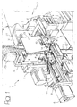
- the number 1 globally designates a device for the mechanised loading of open tip stockings produced on one or more circular machines for stockings and destined to be transferred to a sewing machine for the sewing of the open tips of the stockings.
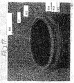
- FIG. 14 through 17 An example of such a stocking is schematically shown in Figures 14 through 17: the stocking, generically designated as C, is formed in correspondence with its open tip A with a thread bridge or cross member P which extends through said open tip A in correspondence with the end of the related tapers and has a length that is substantially equal to the width of the open tip A in its flattened condition shown in Figure 16, when a traction is applied in correspondence with the opposite ends of the bridge P.
- the sock C has a pouch S, to be described in greater detail hereafter.
- the (reinforced) edge of the open tip A is designated as B in these figures.
- the device 1 essentially comprises a support structure 2 which is coupled to a sewing machine, generically designated by the reference M and of a generally conventional type for the sewing of the open tips A of the stockings C.
- a sewing machine for instance, but not necessarily, rectilinear
- the sewing machine includes a conveyor assembly generically designated by the reference 3, also generally conventional and for example of the type described and illustrated in the Italian Patent IT-B-1288456 by the same Applicant.
- Said conveyor assembly includes a pair of horizontal bars 4 which delimit between them a longitudinal guide slit 5 for the insertion of the open tip A (in the flattened and tensioned configuration shown in Figure 16) of each stocking C loaded by the device 1 on the conveyor assembly 3.
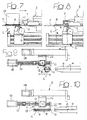
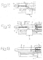
- Said conveyor assembly 3 is also equipped with a pincer-like motorised transfer device, schematically designated by the reference 6 in Figures 7 through 8 and 11 through 13, movable below the two horizontal bars 5 to grip the stocking C introduced into the longitudinal guide slit 5 and transfer it until it is secured to a chain conveyor 7 visible in Figures 7, 8, 12 and 13, which sends the stocking C to the sewing area of the sewing machine.
- a pincer-like motorised transfer device schematically designated by the reference 6 in Figures 7 through 8 and 11 through 13 to 13 movable below the two horizontal bars 5 to grip the stocking C introduced into the longitudinal guide slit 5 and transfer it until it is secured to a chain conveyor 7 visible in Figures 7, 8, 12 and 13, which sends the stocking C to the sewing area of the sewing machine.
- the support structure 2 of the device 1 sustains a first grip assembly, generically designated by the reference number 8 and a second grip assembly generically designated by the reference number 9, whose conformation shall now be described in detail with reference to the embodiment of Figures 1 through 3.
- the first grip assembly 8 includes a pair of horizontal suspensions hooks 10, 11 formed with respective recesses 12, 13 normally aligned with the guide slit 5 of the conveyor assembly 3.
- the hook 10 closer to said conveyor assembly 3 is fastened in overhang to a support 14, more clearly visible in Figure 2, which in turn is integral with a body 15.
- the other hook 11 is borne by a cursor 16 mounted horizontal slidable along the body 15 between a proximal position and a distal position relative to the hook 10.
- the displacement of the hook 11 between said proximal and distal positions is actuated by a worm screw 17 driven by a stepped motor 18 and engaged in a nut screw 19 integral to the cursor 16.
- the body 15 is also movable horizontally, in an orthogonal direction to the direction of displacement of the movable hook 11, between an advanced position in which the recesses 12, 13 of the two hooks 10, 11 are, as stated, aligned with the guide slit 5 of the conveyor assembly 3, and a rear position in which the hooks 10 and 11 are slightly displaced in the direction of the support 2.
- Said displacement is actuated by means of a stepped motor 20, which also actuates for example a screw and nut screw system.
- the arrangement can also be such as to move the body 15, and hence hooks 10 and 11, towards a position yet more advanced than the advanced position described above, for the purpose of making easier and safe the operations of hooking the stocking which shall be described farther on.
- the first grip assembly 8 also includes a lower aspirating device 21 formed by a tubular upright 22 bearing a front inlet 23 and connected to a suction source.
- the lower aspirating device 21 is movable vertically, by means of a fluid cylinder 40, between a raised position and a lowered position (shown with solid line in Figure 3 and in Figures 4 and 5 and 18), and movable horizontally between an advanced position (shown in Figure 3 with solid line) and a rear position (shown in Figure 3 with dashed line) by means of a fluid cylinder not shown, but known by those versed in the art.
- the second grip assembly 9 comprises a body 24 movable horizontally along guides 25 of the support 2 by means of a system with nut screw 26 and screw 27 actuated in rotation by means of a stepped motor 28.
- the displacement of the two jaws 29 between the open and closed position consists of an oscillation: in a variant, not illustrated herein, said displacement could consist of a mutual translation of the two jaws 29.
- the two jaws 29 are also displaceable, by means of a stepped motor 31 and an assembly with screw 36 and nut screw 37, between a raised waiting condition (shown with dashed line in Figure 3 and in Figures 4 and 5) in which they are positioned distally relative to the hooks 10 and 11, and a lowered position, proximal to said hooks 10, 11 of the first grip assembly 8, in the manner illustrated with solid line in Figure 3 and in Figures 6, 7 and 18.
- a blowing device including a pair of holed manifolds 32 connected to a source of pressurised air to direct respective air jets downwards, or towards the hooks 10, 11 of the first grip assembly 8.
- an upper aspirating device including an elongated conduit 33 interposed between the manifolds 32 of the blowing device and connected to a source of vacuum.
- blowing device 32 and the upper aspirating device 33 of the second grip assembly 9, as well as the aspirating device 21 of the first grip assembly 8 are shown summarily in Figure 3, whilst the respective sources of pressurised air and of suction are not shown for the sake of simplicity of illustration and because they are wholly conventional.
- the function of the devices 21, 32 and 33 shall be clarified hereafter.
- the body 24 bearing the first and the second grip assembly 8, 9 is positioned on the support 2 side by side with the horizontal bars 4 of the conveyor assembly 3.
- the hook 11 of the first grip assembly 8 is positioned in the proximal position with respect to the other hook 10 and both are in the advanced position in which the respective recesses 12, 13 are aligned horizontally with the guide slit 5 of the conveyor assembly 3.
- the hooks 10 and 11 may be preliminarily positioned, as explained previously, in a yet more advanced position.
- the lower aspirating device 21 is inactive and in raised and rear position.
- the jaws 29 are in a raised and open position, and both the blowing device 32 and the upper intake device 33 are inoperative.
- This operation of positioning the stocking C on the first grip assembly 8 of the loading device 1 can be performed manually in extremely simple and rapid fashion by an operator or, alternatively, in automated fashion.
- the stocking C thus remains loosely suspended by its bridge P engaged in the recesses 12 and 13 of the hooks 10 and 11, as shown in Figures 4 and 9.
- the subsequent phase shown in Figures 5 and 10 consists of moving the hook 11 to its distal position relative to the hook 10, by means of the screw 17 and nut screw 19 system and the stepped motor 18.
- the bridge P is under traction: since in this condition its length is, as explained above, substantially equal to the width of the opening A of the tip of the stocking C, said tip is also under tension in a flattened condition corresponding to the one shown in Figure 16, with its pouch S positioned dorsally in soft condition.
- the activation is commanded of the upper aspirating device 33 which, acting on the edge B of the open tip A, aligns it horizontally against the lower side of the grip assembly 9.
- the subsequent phase entails the closing of the jaws 29, by means of the fluid actuator 30, in such a way as to grip between them the edge B thus aligned by the upper aspirating device 33, in the manner shown in Figure 6 and also in Figure 18.
- the lower aspirating device 12 of the first grip assembly 8 is commanded to approach the dorsal area of the stocking C situated below the hooks 10, 11, and it is activated.
- the inlet 23 of the lower intake device 21 is then moved downwards, by means of the fluid actuator 40, in such a way as to tension the elasticised ranks (designated with the reference R3 in Figure 17, whereon the description shall return farther on) of the stocking C situated immediately below the edge B held by the jaws 29.
- This phase is also shown in Figure 6 and in Figure 18.
- the fluid actuator 30 commands the opening of the jaws 29 and the actuator 31 commands the subsequent rise of the second grip assembly 9, thereby freeing the edge B positioned above the bars 4.
- the lower aspirating device 21 of the first grip assembly 8 is deactivated and brought back to the rearwards and raised starting position.
- the hook 11 of the first grip assembly 8 is then moved to the proximal position towards the other hook 10, by means of the motorised actuator 18 and the screw and nut screw 17, 19 system and then the entire first grip assembly 8 is moved to the rearwards position by means of the motorised actuator 20, to free the bridge P of the stocking C. This step is shown in Figure 12.
- the gripping device 6 of the conveyor assembly 3 is then activated and grips on the opposite sides the stocking C immediately below the horizontal bars 4, in the manner shown in Figure 7.
- the body 24 bearing the first and the second grip assembly 8, 9 is then translated to the starting position, to repeat the loading cycle of the next stocking, whilst the stocking C thus inserted between the horizontal bars 4 of the conveyor assembly 3 is translated along the guide slit 5 by the gripping device 6 until it is grabbed by the chains 7, in the manner shown in Figure 13.
- the stocking C is thus sent to the sewing machine for the sewing of the tip A.
- said method consists of forming the thread bridge P joined at its ends to two opposite areas of the open tip A of the stocking C which correspond to the end of the tapers of the tip itself, as stated for a length that is substantially equal to the width of the tip A when said tip A is flattened and tensioned.
- the method for preparing the stocking C comprises a series of preliminary operations which are generally known in themselves, for example similar to those described in European Patent EP-B-057664 by the same Applicant.
- the stocking is woven on an electronic circular machine with needle selection.
- an electronic circular machine with needle selection By way of example, one can consider the preparation on a circular machine for stockings with diameter 3-3/4" with 144 needles.
- a complete rank R1 is executed with the same yarn as the stocking, but woven with thicker stitches and reinforced with the addition of a second thread.
- Another complete rank R2 is then executed with the same thread used for the stocking, but woven with loose stitches.
- the reinforced rank R1 and the loose rank R2 start and end in correspondence with the end of one of the tapers of the tip of the stocking.
- a thread change is then completed and a certain number (for example five) of ranks R3 is executed with elastic yarn having a finer count than the one used for the stocking (40/2 DEN).
- the height of said fine ranks, including the loose rank, measured with the fabric tensioned will be, for example, in the order of 7-8 mm.
- a new thread change is carried out and a certain number (for example, eight) of reinforced ranks R4 are executed, inserting larger threads than the one used for the body of the stocking.
- the second drop of the machine intervenes and, selecting the needles in the stitch one by one, executes two complete ranks R5 for example with a polyester thread with count 200/8 DEN, and then selects ten needles before the first vertex of the heel and ten needles subsequent to the second vertex of the heel, thereby creating the thread bridge P between the two vertices.
- the system then continues on the first drop in order to execute a certain number (for example eight-ten) of additional reinforced ranks R6 which complete the edge B of the open tip A of the stocking C.
- the length of the bridge P be equal to the width of the open tip A of the stocking C in the flattened condition, and when both (tip A and bridge P) are tensioned, in the manner shown in Figure 16.
- the bridge P it will be necessary to act on the tension of the stitching of the reinforced edge B.
- the bridge P may be elongated to the necessary measure by intervening on the second drop of the circular stocking machine and then unloading the two plus two needles that will form the bridge P.
- Two needles at about 10-15 mm after the first taper and two needles at about 10-15 mm after the second taper will in this case rise on the second drop to unload the reinforced stitches.
- the thread bridge P may be formed by multiple threads.
- the device may be equipped with a shear cutting assembly for the separation of the thread bridge P from the tip A of the stocking C after it has been inserted in the guide slit 5 of the conveyor assembly 3. This would have the purpose of simplifying the release of the stocking C by the hooks 10 and 11.
Landscapes
- Engineering & Computer Science (AREA)
- Textile Engineering (AREA)
- Sewing Machines And Sewing (AREA)
- Socks And Pantyhose (AREA)
Applications Claiming Priority (2)
| Application Number | Priority Date | Filing Date | Title |
|---|---|---|---|
| ITTO20030253 | 2003-04-02 | ||
| ITTO20030253 ITTO20030253A1 (it) | 2003-04-02 | 2003-04-02 | Metodo e dispositivo per il caricamento di calze sul |
Publications (2)
| Publication Number | Publication Date |
|---|---|
| EP1464748A2 true EP1464748A2 (de) | 2004-10-06 |
| EP1464748A3 EP1464748A3 (de) | 2005-12-07 |
Family
ID=32843932
Family Applications (1)
| Application Number | Title | Priority Date | Filing Date |
|---|---|---|---|
| EP04007783A Withdrawn EP1464748A3 (de) | 2003-04-02 | 2004-03-31 | Verfahren und Vorrichtung zum Beschicken von Strümpfen zur Transporteinrichtung einer Nähmaschine |
Country Status (2)
| Country | Link |
|---|---|
| EP (1) | EP1464748A3 (de) |
| IT (1) | ITTO20030253A1 (de) |
Cited By (1)
| Publication number | Priority date | Publication date | Assignee | Title |
|---|---|---|---|---|
| CN117265784A (zh) * | 2023-09-27 | 2023-12-22 | 浙江广泰德达袜业有限公司 | 一种用于袜子缝头机的送料装置 |
Family Cites Families (2)
| Publication number | Priority date | Publication date | Assignee | Title |
|---|---|---|---|---|
| US6003345A (en) * | 1997-01-03 | 1999-12-21 | B.B. & T. Knitting Limited | Knit garment and orientation method |
| US6158367A (en) * | 1999-03-17 | 2000-12-12 | B. B. & S. Knitting Consultants | Apparatus and method for automatically orienting hosiery articles for closing toe ends thereof |
-
2003
- 2003-04-02 IT ITTO20030253 patent/ITTO20030253A1/it unknown
-
2004
- 2004-03-31 EP EP04007783A patent/EP1464748A3/de not_active Withdrawn
Cited By (1)
| Publication number | Priority date | Publication date | Assignee | Title |
|---|---|---|---|---|
| CN117265784A (zh) * | 2023-09-27 | 2023-12-22 | 浙江广泰德达袜业有限公司 | 一种用于袜子缝头机的送料装置 |
Also Published As
| Publication number | Publication date |
|---|---|
| EP1464748A3 (de) | 2005-12-07 |
| ITTO20030253A1 (it) | 2004-10-03 |
Similar Documents
| Publication | Publication Date | Title |
|---|---|---|
| JP2580088B2 (ja) | パンティストッキングの自動形成、製造装置及び形成方法 | |
| JP6530197B2 (ja) | ミシン | |
| JPH0860502A (ja) | 円筒状ストッキング編機からのストッキング搬送方法及びその装置 | |
| CZ20011295A3 (cs) | Způsob a zařízení pro ąití ąpičky ponoľky | |
| KR20080045071A (ko) | 재봉기 | |
| ITFI20010038A1 (it) | Dispositivo per il prelievo di un manufatto tubolare a maglia da una macchina da maglieria e per la cucitura della punta | |
| TW504528B (en) | Method and device for producing tubular knitted articles and for closing their toes | |
| EP1464748A2 (de) | Verfahren und Vorrichtung zum Beschicken von Strümpfen zur Transporteinrichtung einer Nähmaschine | |
| KR20030089700A (ko) | 관형상 편직물의 발끝부를 봉합하는 제조방법 및 장치 | |
| EP0537323B1 (de) | Verfahren und vorrichtung zum herstellen und umdrehen eines werkstückes | |
| JP2011125387A (ja) | ミシン | |
| EP0177159B1 (de) | Verfahren und Vorrichtung um die Zehenden von Strümpfen zu schliessen | |
| US5207165A (en) | Method for varying the curvature of the sewn tip of stockings with a sewing machine and device for carrying out said method | |
| EP0194135A2 (de) | Verfahren und Vorrichtung um Hosenbundenden fertig zu machen | |
| JP2011125386A (ja) | ミシン | |
| KR930005923B1 (ko) | 원단 봉침기 | |
| US2905366A (en) | Apparatus for feeding hosiery onto a receiving member | |
| KR101091993B1 (ko) | 재봉틀의 구동장치 | |
| CN208293226U (zh) | 一种缝纫机挑线结构 | |
| CN116555970B (zh) | 一种横机无废纱编织手套工艺 | |
| JPH0450349A (ja) | 横編機に付設する耳糸の自動引き込み装置 | |
| EP1896638A1 (de) | Vorrichtung zur handhabung von schlauchförmigen strickwaren, insbesondere socken und dergleichen | |
| IT201900006744A1 (it) | Apparato di gestione di sfridi di cucitura in macchine per cucire con punto catenella | |
| HU186193B (en) | Method and apparatus for knitting sock respectively stocking formed by closed toe part and heel solution on flat-bed knitter of weft system | |
| ITPI20070074A1 (it) | Sistema per la chiusura della calza su macchine circolari per produzione di calzini tubolari in maglia alla fine del calzino |
Legal Events
| Date | Code | Title | Description |
|---|---|---|---|
| PUAI | Public reference made under article 153(3) epc to a published international application that has entered the european phase |
Free format text: ORIGINAL CODE: 0009012 |
|
| AK | Designated contracting states |
Kind code of ref document: A2 Designated state(s): AT BE BG CH CY CZ DE DK EE ES FI FR GB GR HU IE IT LI LU MC NL PL PT RO SE SI SK TR |
|
| AX | Request for extension of the european patent |
Extension state: AL LT LV MK |
|
| PUAL | Search report despatched |
Free format text: ORIGINAL CODE: 0009013 |
|
| AK | Designated contracting states |
Kind code of ref document: A3 Designated state(s): AT BE BG CH CY CZ DE DK EE ES FI FR GB GR HU IE IT LI LU MC NL PL PT RO SE SI SK TR |
|
| AX | Request for extension of the european patent |
Extension state: AL LT LV MK |
|
| 17P | Request for examination filed |
Effective date: 20060330 |
|
| 17Q | First examination report despatched |
Effective date: 20060704 |
|
| AKX | Designation fees paid |
Designated state(s): DE IT TR |
|
| STAA | Information on the status of an ep patent application or granted ep patent |
Free format text: STATUS: THE APPLICATION IS DEEMED TO BE WITHDRAWN |
|
| 18D | Application deemed to be withdrawn |
Effective date: 20091001 |