EP1464976A2 - Aimant pour un spectromètre à RMN - Google Patents
Aimant pour un spectromètre à RMN Download PDFInfo
- Publication number
- EP1464976A2 EP1464976A2 EP04008113A EP04008113A EP1464976A2 EP 1464976 A2 EP1464976 A2 EP 1464976A2 EP 04008113 A EP04008113 A EP 04008113A EP 04008113 A EP04008113 A EP 04008113A EP 1464976 A2 EP1464976 A2 EP 1464976A2
- Authority
- EP
- European Patent Office
- Prior art keywords
- access port
- magnet
- coil
- sample
- access
- Prior art date
- Legal status (The legal status is an assumption and is not a legal conclusion. Google has not performed a legal analysis and makes no representation as to the accuracy of the status listed.)
- Granted
Links
- 239000000523 sample Substances 0.000 claims abstract description 174
- 238000005259 measurement Methods 0.000 claims abstract description 64
- 230000005291 magnetic effect Effects 0.000 claims description 91
- 238000005481 NMR spectroscopy Methods 0.000 claims description 90
- 238000001514 detection method Methods 0.000 claims description 37
- 239000004020 conductor Substances 0.000 claims description 20
- 238000004804 winding Methods 0.000 abstract description 16
- 238000003780 insertion Methods 0.000 description 29
- 230000037431 insertion Effects 0.000 description 29
- 238000000034 method Methods 0.000 description 12
- 230000007246 mechanism Effects 0.000 description 11
- 230000005855 radiation Effects 0.000 description 10
- 239000007788 liquid Substances 0.000 description 9
- 239000001307 helium Substances 0.000 description 8
- 229910052734 helium Inorganic materials 0.000 description 8
- SWQJXJOGLNCZEY-UHFFFAOYSA-N helium atom Chemical compound [He] SWQJXJOGLNCZEY-UHFFFAOYSA-N 0.000 description 8
- 230000035945 sensitivity Effects 0.000 description 6
- 230000001678 irradiating effect Effects 0.000 description 5
- 230000007423 decrease Effects 0.000 description 3
- 238000012360 testing method Methods 0.000 description 3
- IJGRMHOSHXDMSA-UHFFFAOYSA-N Atomic nitrogen Chemical compound N#N IJGRMHOSHXDMSA-UHFFFAOYSA-N 0.000 description 2
- 238000006243 chemical reaction Methods 0.000 description 2
- 238000010586 diagram Methods 0.000 description 2
- 239000007789 gas Substances 0.000 description 2
- 230000005415 magnetization Effects 0.000 description 2
- 229910000657 niobium-tin Inorganic materials 0.000 description 2
- 238000012546 transfer Methods 0.000 description 2
- 238000001816 cooling Methods 0.000 description 1
- 230000001419 dependent effect Effects 0.000 description 1
- 230000000694 effects Effects 0.000 description 1
- 230000005294 ferromagnetic effect Effects 0.000 description 1
- 239000003302 ferromagnetic material Substances 0.000 description 1
- 230000005484 gravity Effects 0.000 description 1
- 238000012966 insertion method Methods 0.000 description 1
- 238000009434 installation Methods 0.000 description 1
- 229910052757 nitrogen Inorganic materials 0.000 description 1
- 238000012545 processing Methods 0.000 description 1
- 102000004169 proteins and genes Human genes 0.000 description 1
- 108090000623 proteins and genes Proteins 0.000 description 1
- 238000010791 quenching Methods 0.000 description 1
- 230000000171 quenching effect Effects 0.000 description 1
- 239000003507 refrigerant Substances 0.000 description 1
Images




Classifications
-
- G—PHYSICS
- G01—MEASURING; TESTING
- G01R—MEASURING ELECTRIC VARIABLES; MEASURING MAGNETIC VARIABLES
- G01R33/00—Arrangements or instruments for measuring magnetic variables
- G01R33/20—Arrangements or instruments for measuring magnetic variables involving magnetic resonance
- G01R33/28—Details of apparatus provided for in groups G01R33/44 - G01R33/64
- G01R33/38—Systems for generation, homogenisation or stabilisation of the main or gradient magnetic field
- G01R33/381—Systems for generation, homogenisation or stabilisation of the main or gradient magnetic field using electromagnets
- G01R33/3815—Systems for generation, homogenisation or stabilisation of the main or gradient magnetic field using electromagnets with superconducting coils, e.g. power supply therefor
Definitions
- the present invention relates to a magnet for an NMR (Nuclear Magnetic Resonance) analyzer and an NMR analyzer, specifically to an NMR analyzer having a sample insertion port which enables a measurement sample to be inserted in a direction perpendicular to the main magnetic field.
- NMR Nuclear Magnetic Resonance
- a magnet for an NMR analyzer consists of coaxially nested, multilayer solenoid coils 4, as shown in FIG.9, in which the magnetic axis is vertically oriented.
- An access port 21 vertically passes through the magnet in the vicinity of the magnetic axis so that a sample can be inserted.
- a measurement sample is inserted from above and a probe 10 containing an antenna (coil) for detecting signals is inserted from below.
- a conventional NMR analyzer uses a saddle-type or bird-cage-type antenna (coil).
- FIG.2 shows the positional relationships between a sample, a detection coil and the magnetic field.
- a solenoid-type detection coil 5 having a coil axis (virtual axis) perpendicular to the main magnetic field generated by a magnet and disposing a sample 11 so that it passes through the coil 5, the sensitivity can be increased by a factor of at least 1.4 as compared to the sensitivity when only the coil shape is considered.
- Japanese published patent application Hei 07-333311 discloses an example of a sample insertion method and the shape of a magnet which enables a sample to be positioned and the detection coil to be configured as mentioned above.
- the document describes a method in which a sample 11 of short length is mounted to a probe so that it is perpendicular to the magnetic axis, and the sample and the probe inserted into the magnet.
- document 2 does not mention a method that improves the sensitivity by using a solenoid-type antenna, it describes a split-type magnet.
- the described split-type magnet having an insertion port located in the magnet's gap, it is theoretically possible to dispose a sample, which passes through a solenoid-type antenna, at the center of the magnetic field so that the sample is perpendicular to the main magnetic field.
- Japanese published patent application Hei 07-240310 describes a method to dispose a sample and a probe in the gap of the magnet.
- the splittype magnet since the splittype magnet must have a gap to obtain maximum strength in the magnetic field, the electric current cannot flow through the most effective area. Accordingly, to generate the necessary strength in the central magnetic field, more current must flow through this magnet than the amount of current that flows through a magnet without a gap. Furthermore, to achieve the necessary uniformity of the magnetic field, the configuration of the coil is limited.
- the diameter of the split-type magnet increases and the generated electromagnetic force also increases.
- a coil that generates a magnetic field in the reverse direction of the main magnetic field must be installed. Thus, it is very difficult to create such a magnet.
- the first objective of the present invention is to provide a magnet for an NMR analyzer and an NMR analyzer using the magnet in order to improve NMR measurement sensitivity; and the magnet utilizes a solenoid-type detection coil and the configuration in which a measurement sample passes through the detection coil and is perpendicular to the main magnetic field is easily achieved.
- the second objective of the present invention is to provide a magnet for an NMR analyzer which facilitates replacement of a sample.
- the third objective of the present invention is to provide a magnet for an NMR analyzer that can measure the NMR of a sample while irradiating a light onto the sample.
- an electric conductor is wound around an axis 15 as a magnetic axis, and by turning on the electric conductor, a magnetic field that includes a measurement space 3 for conducting measurement is generated in the space surrounded by the electric conductor.
- the electric conductor is wound such that the magnet comprises a first access port 1 through which access from the outside of the magnet to the measurement space is possible via the vicinity of the axis, and a second access port 2 which enables access in a direction different from that of the first access port, and the electric conductor does not interfere with the area where the first and second access ports are located.
- the effective diameter of the first and second access ports is defined as the diameter of a cylinder which can be inserted into the access port.
- the effective diameter of the second access port is smaller than that of the first access port.
- a first coil 41 in which an electric conductor is wound around an axis 15 as a magnetic axis is disposed facing a second coil 42 which is formed in the same manner as the first coil and wound around the same axis.
- a magnetic field that includes a measurement space 3 is formed inside the space surrounded by the first and second coils, and the magnet has a first access port 1 through which access to the measurement space 3 is possible in the direction of the axis 15.
- a second access port 2 which enables access in a direction different from that of the first access port is provided in a clearance between the first coil and the second coil.
- the effective diameter of the first and second access ports is defined as the diameter of a cylinder which can be inserted into the access port.
- the effective diameter of the second access port is smaller than that of the first access port. It is desirable that the effective diameter be 20 mm or less, and more preferably 10 mm or less.
- a magnet for an NMR analyzer in accordance with a third aspect of the present invention is according to either the aspect 1 or 2, wherein the first and second access ports pass through the magnet.
- a magnet for an NMR analyzer in accordance with a fourth aspect of the present invention is according to any one of the aspects 1 through 3 and comprises at least one superconducting coil.
- a magnet for an NMR analyzer in accordance with a fifth aspect of the present invention is according to any one of the aspects 1 through 4, wherein the axis 15 is oriented horizontally.
- a magnet for an NMR analyzer in accordance with an eighth aspect of the present invention is according to any one of the aspects 1 through 5, wherein the first access port 1 (see FIGS.1 and 7) is oriented horizontally and the second access port 2 is not positioned vertically (see FIG.7).
- a magnet for an NMR analyzer in accordance with a seventh aspect of the present invention is according to any one of the aspects 1 through 6, and further comprises a third access port 22 (see FIG.8) which is different from the first and second access ports.
- a magnet for an NMR analyzer in accordance with an eighth aspect of the present invention is according to the aspect 7, wherein the third access port 22 passes through the measurement space 3 and passes through the magnet.
- a magnet for an NMR analyzer in accordance with a ninth aspect of the present invention is according to any one of the aspects 1 through 8 and further comprises more than one access port having a noncircular sectional view.
- An NMR analyzer in accordance with a tenth aspect of the present invention comprises a magnet according to any one of the aspects 1 through 9.
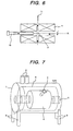
- An NMR analyzer in accordance with an eleventh aspect of the present invention is according to the aspect 10, wherein a probe 10 for measuring an NMR signal is inserted from a first access port 1, and a sample 11 to be measured (see FIG.6) is inserted from a second access port 2 (see FIG.1), and the positions of the probe and the sample meet in the measurement space 3 so that NMR measurement can be conducted.
- An NMR analyzer in accordance with a twelfth aspect of the present invention comprises a magnet in which an electric conductor is wound around an axis 15 (see FIG.4), and by turning on the electric conductor, a magnetic field that includes a measurement space 3 is generated in the space surrounded by the electric conductor; a first access port for accessing the measurement space 3 in the axial direction; and a second access port 2 which enables access in the different direction from the first access port 1, wherein a probe 10 for measuring.an NMR signal is inserted from a first access port 1, and a sample 11 to be measured is inserted from a second access port 2, and the positions of the probe and the sample meet in the measurement space 3 so that NMR measurement can be conducted.
- a first coil 41 in which an electric conductor is wound around an axis is disposed facing a second coil 42 which is formed in the same manner as the first coil and wound around the same axis, and a magnetic field that includes a measurement space 3 is formed inside the space surrounded by the first and second coils (see FIG.5); and the NMR analyzer further comprises a first access port 1 through which access to the measurement space 3 is possible in the direction of the axis 15 and a second access port 2 which enables access in the different direction from the first access port 1.
- a probe 10 for measuring an NMR signal is inserted from a first access port 1, and a sample 11 to be measured is inserted from a second access port 2, and the positions of the probe and the sample meet in the measurement space 3 so that NMR measurement can be conducted (see FIG.6).
- the second access port passes through the magnet (see FIGS.1 and 8).
- An NMR analyzer in accordance with a fifteenth aspect of the present invention is according to any one of the aspects 12 through 14, wherein the magnet comprises at least one superconducting coil.
- An NMR analyzer in accordance with a sixteenth aspect of the present invention is according to any one of the aspects 12 through 14, wherein the magnet is positioned such that the axis 15 is oriented horizontally.
- An NMR analyzer in accordance with a seventeenth aspect of the present invention is according to the invention 16, wherein the first access port 1 is oriented horizontally and the second access port 2 is not vertically oriented.
- An NMR analyzer in accordance with an eighteenth aspect of the present invention is according to any one of the aspects 12 through 17, and further comprises a third access port 22 (see FIG.8) different from the first and second access ports.
- An NMR analyzer in accordance with a nineteenth aspect of the present invention is according to the aspect 18, wherein the third access port 22 passes through the measurement space 3 and passes through the magnet.
- An NMR analyzer in accordance with a twentieth aspect of the present invention is according to any one of the aspects 12 through 19, and further comprises more than one access port having a noncircular sectional view.
- the magnet according to the present invention has two access passages for accessing, from the outside of the coil, the measurement area 3 located inside the magnetic field surrounded by coil windings, and the first passage is positioned in the direction of the coil axis 15 and the second passage passes through a clearance 12 (see FIG.4) in the coil winding portion.
- a probe 10 (see FIG.6) equipped with a solenoid-type detection coil 5 is inserted from the first passage so that the detection coil is positioned in the measurement space 3. Further, by positioning a sample in the measurement space 3 through the second passage, it is possible to position the sample so that it is perpendicular to the direction of the main magnetic field and also passes through the solenoid-type detection coil.
- the size of the access port to ensure the second passage is made as small as possible so that a sample can be inserted, and a clearance 12 provided in the coil winding portion is also minimized.
- This configuration makes it possible to minimize decrease in strength in the central magnetic field due to the presence of the clearance 12 and also to minimize turbulence of the uniformity of the magnetic field.
- an access port having a large effective diameter is regarded as a first access port and an access port having a smaller effective diameter is regarded as a second access port.
- the first access port is positioned on the magnetic axis and the second access port is positioned in the clearance between coil windings.
- a probe 10 having a larger sectional area than that of a sample is inserted from the first access port, and the sample is inserted from the second access port, and their positions meet in the measurement space.
- the flow method enables the sample to be continuously or intermittently input and moved to the measurement space through a sample carrier pipe.
- the first insertion port passes through the magnet, when a probe is inserted from one side, access to the sample from the other side is possible. Accordingly, it is possible to irradiate light (electromagnetic waves) or the like to the measurement sample through an access passage from the other side. As a consequence, it is possible to irradiate a ray of Light (electromagnetic waves) onto a photoactive or photosensitive measurement sample and simultaneously measure NMR signals indicating the reaction.
- the strength of the magnetic field can be improved.
- the center of gravity of the entire magnet can be lowered.
- the axis is oriented vertically. A probe is inserted from below along the axis. As a result, the position of the entire magnet is elevated and the sample insertion port is located at an elevated position.
- the position of the sample insertion port can be lowered and also moved from the center of the magnet toward the edge, thereby increasing accessibility.
- the measurement space 3 it is also possible to increase accessibility to the measurement space 3 by providing a third access port 22 different from the first and second access ports.
- the third port can pass through the measurement space 3 and completely pass through the magnet. Therefore, it is possible to incorporate a device for irradiating a ray of light (electromagnetic wave) onto the measurement sample, detecting the transmitted or scattered light, and retrieving structure information of the sample.
- the sectional area of the access port is made oval or rectangular instead of circular. This makes the sectional area of the access port large without increasing the size of the magnet's gap. Consequently, accessibility to the measurement space 3 increases.
- a multilayer coil group in which a plurality of coils 43, 44 and 45 are coaxially nested and wound is disposed so that the axis 15 is horizontal.
- each coil is wound so that a clearance 12 is created in the central portion of each coil 46 to create a port for accessing the magnet's central portion.
- the size of the clearance 12 in the central portion of the coil winding provided for ensuring a port is approximately 40 mm wide.
- the coil wire is wound such that the clearance is made as small as possible.
- a shim coil group (not shown) is disposed outside the multilayer coil group to compensate for an axisymmetric and nonaxisymmetric error magnetic field.
- another shim coil group is disposed inside the multilayer coil.
- the multilayer coil group consists of nine coils (not shown). Three coils located radially on the outer side are wound with NbTi wire, and other coils are wound with Nb 3 Sn wire so that each coil is appropriately superconductive according to the strength in the magnetic field to which each coil is exposed.
- Coils composing a multilayer coil group are superconductively connected in an electrical series circuit to form a current loop, and the multilayer coil group is put in motion by the permanent current mode.
- the shim coil group located on the outer side is wound with NbTi wire and generates a magnetic field that compensates for X, Y, XY, X2-Y2, ZX and ZY terms which are generally expressed as kinds of an NMR magnet's error magnetic fields.
- the shim coil group located on the inner side is wound with Nb 3 Sn wire and generates a magnetic field that compensates for those error magnetic fields and also generates a higher- order compensation magnetic field.
- the inner diameter of the coil group including shim coils is approximately 80 mm and the outer diameter is approximately 700 mm.
- This configuration allows the magnet to generate a magnetic field in which the strength in the central magnetic field is 14.1 T (proton resonance frequency 600 MHz) and turbulence of the magnetic field inside the spherical surface with a diameter of 20 mm is 1 ppb or less, and the attenuation rate of magnetic field's strength is approximately 2 ppb/hour or less.
- Coils need to operate immersed in liquid helium and they are placed inside the container 6 that contains liquid helium as a refrigerant. Furthermore, to reduce the amount of heat seepage into the liquid helium container 6, a radiation shield and a heat-insulating vacuum layer are formed outside the liquid helium layer and the liquid nitrogen layer (not shown) to cool the radiation shield is also provided.
- the magnet has two access ports: one for radially accessing the measurement area located at the center of the magnet and the other for axially accessing the same area along the coil's axis.
- Each port forms a part of the aforementioned liquid helium container 6, radiation shield and heat-insulating vacuum layer, and the ports are also formed such that both access port meet in the central portion of the magnet.
- Both access ports pass through the vacuum container, liquid helium container and the coil. Therefore, in the magnet, access to the measurement space 3 located in the central portion of the magnet is possible from four directions.
- the inner diameter of the axial access port is 54 mm, and the inner diameter of the radially access port is 20 mm.
- An NMR analyzer mainly consists of a magnet for generating a uniform magnetic field, an antenna coil for detection, an RF radiation coil for irradiating electromagnetic waves, a mechanism for adjusting a sample's temperature, a mechanism for holding and rotating the sample, a signal processing device and a control device.
- an antenna coil for detection an RF (Radio Frequency) radiation coil, a mechanism for adjusting a sample's temperature and a mechanism for holding and rotating the sample are integrated into a probe and inserted into the magnet.
- RF Radio Frequency
- an access port 2 vertically passes through the magnet on the magnetic axis, and a probe 10 is generally inserted into the access port from below and a sample 11 is inserted into the access port from above.
- a probe 10 having an RF radiation coil and a solenoid-type detection antenna is axially inserted into the access port 1 (see FIG.6), and a measurement sample contained in a 5 to 10 mm test tube is radially inserted into the access port 2 from above (see FIG.1).
- a gas flow mechanism for adjusting a measurement sample's temperature and a mechanism for rotating the sample are inserted into the access port 2 from below, and those mechanisms, the above-mentioned probe and sample meet in the measurement space 3 located in the central portion of the magnet.
- An NMR analyzer requires a detection antenna (detection coil) to detect magnetization perpendicular to the main magnetic field. Therefore, the detection antenna (detection coil) must be positioned so as to detect magnetization generated in the direction of the magnet's radius.
- the axial direction of the detection antenna (solenoid-type coil 5) disposed in the measurement space 3 as shown in FIG.2 is perpendicular to the direction of the magnet's main magnetic field.
- the signal detection efficiency which is determined by the shape of the coil and positional relationship between the coil and the sample, is at least 1.4 times more than that of the conventional NMR analyzer. Consequently, more sensitive measurement can be achieved.
- an access port in the direction of the magnet's radius which is the same as the above sample insertion port, is formed such that it is perpendicular to the sample insertion port, and the probe can be inserted from the access port.
- the electromagnetic force applied to the coil increases, and the strength in the magnetic field applied to the superconductive windings of the coil increases.
- the superconductive windings can conduct electric current in the substantially superconductive state only when the strength in the magnetic field is below a certain level.
- this embodiment can reduce the number of coils from eleven to nine because it generates a magnetic field with a strength of 14.1 T while maintaining the uniformity. Consequently, the strength in the magnetic field which the coil withstands can be reduced from 16.2 T to 15.4 T, thereby reducing the stress value by approximately 30 MPa in an area where the electromagnetic force is severe.
- an RF radiation coil, a detection antenna, a mechanism for rotating a sample and a mechanism for adjusting the sample's temperature are integrated into one unit and installed.
- That configuration makes the mounting space inside the probe become wider, and limitation to the mounting of the RF radiation coil and the detection antenna is eased. As a result, the RF coil and the antenna can be more effective.
- This opposite-side access port can be used to introduce light when a photoactive sample is measured.
- a coil is wound such that a clearance 12 is made in the central portion of the coil winding in order to create a sample insertion port.
- a solenoid coil group 1 (numeral 41 in FIG.5) and a similar solenoid coil group 2 (numeral 42 in FIG.5) both of which are wound around the same axis 15 are disposed with a given interval provided therebetween.
- Coils used for this method are easy to make, and designing of the uniform magnetic field is also easy because the coil winding can be symmetrical. Also, a relatively uniform electromagnetic force can be applied, which is an advantage in terms of electromagnetic force resistance.
- minimizing the gap for enabling the insertion of a measurement sample facilitates the generation of the uniform magnetic field.
- the magnetic axis 15 is horizontally oriented.
- the direction in which a magnetic field is generated is not limited to the horizontal direction.
- a magnetic field is vertically generated.
- a magnetic axis is vertically oriented and a sample is inserted from above (2 m or more above the floor surface).
- the sample insertion port is located in the central portion of the magnet. Therefore, the position at which a sample is inserted is 2 m or less, thereby making sample replacement easy.
- the magnetic axis 15 is horizontally oriented and the sample insertion port is vertically oriented.
- all it takes to do is to position a sample insertion port such that a sample is inserted in the direction perpendicular to the magnetic axis, and it does not have to be vertically oriented.
- the diameter of the magnet including the entire cryostat is approximately 1.6 m, and in the floor-type magnet, a sample insertion port is located at least 1.6 m above the floor surface. In this case, to replace a sample, it is necessary for someone to stand by the magnet, to stretch out an arm about 80 cm and to replace the sample at a position that is 1.6 m high.
- the entrance of the sample port is located closer to an operator and the height of the port is also lower, facilitating the sample replacement.
- the desirable angle of incline is 30 to 45 degrees from the vertical.
- the magnet magnetic field generation means 4
- the bottom port which is opposite to the aforementioned sample insertion port.
- the sample insertion port at an inclined angle from the vertical, it is possible to ensure a clearance between the magnet and the floor surface, thereby improving accessibility.
- light can be introduced from an unused access port which is the other side of the probe insertion port so as to light the sample.
- This port is equipped with an electromagnetic wave radiation device for irradiating a far-infrared ray with a wavelength of 0.1 mm or less, visible ray, X-ray and so on.
- Some kinds of proteins are photoactive, and their structure changes by irradiation of light. Therefore, this embodiment enables the NMR analyzer to measure photoactive reactions and structure changes.
- a probe insertion port and a sample insertion port cross at right angles at the center of the magnet.
- a third access port 22 can be provided which is different from the probe insertion port and the sample insertion port.
- light can be introduced from an unused access port which is the other side of the probe insertion port.
- an analyzer for irradiating a ray of light onto a sample detecting light transmitted or scattered from a sample and retrieving structure information of the sample
- both a port for introducing light toward the sample and a port for detection are necessary.
- Those ports do not have to be positioned linearly, and they can be connected at a certain angle according to the transmitted or scattered light.
- a sample is inserted into the second access port 2, which is a sample insertion port, from above, and gas for adjusting the sample's temperature and rotating the sample can be introduced from below.
- gas for adjusting the sample's temperature and rotating the sample can be introduced from below.
- a sample carrier pipe at an access port for sample insertion so as to continuously and movably input measurement samples into the measurement space.
- a clearance is formed in the coil winding portion, an access port 2 is provided through which a sample is inserted from the clearance into the measurement space 3 located at the center of the magnet, and another access port is also provided through which a probe is inserted into the measurement space along the magnetic axis.
- an access port which is not occupied by a probe or a sample, to the measurement space, it is possible to provide an NMR measurement device which can externally introduce light for measurement.
Landscapes
- Physics & Mathematics (AREA)
- Electromagnetism (AREA)
- Condensed Matter Physics & Semiconductors (AREA)
- General Physics & Mathematics (AREA)
- Investigating Or Analyzing Materials By The Use Of Magnetic Means (AREA)
- Other Investigation Or Analysis Of Materials By Electrical Means (AREA)
Applications Claiming Priority (2)
| Application Number | Priority Date | Filing Date | Title |
|---|---|---|---|
| JP2003100120A JP4030910B2 (ja) | 2003-04-03 | 2003-04-03 | Nmr分析装置用マグネットおよびそれを用いたnmr分析装置 |
| JP2003100120 | 2003-04-03 |
Publications (3)
| Publication Number | Publication Date |
|---|---|
| EP1464976A2 true EP1464976A2 (fr) | 2004-10-06 |
| EP1464976A3 EP1464976A3 (fr) | 2005-07-20 |
| EP1464976B1 EP1464976B1 (fr) | 2013-01-23 |
Family
ID=32844703
Family Applications (1)
| Application Number | Title | Priority Date | Filing Date |
|---|---|---|---|
| EP04008113A Expired - Lifetime EP1464976B1 (fr) | 2003-04-03 | 2004-04-02 | Aimant pour un spectromètre à RMN |
Country Status (3)
| Country | Link |
|---|---|
| US (3) | US7141977B2 (fr) |
| EP (1) | EP1464976B1 (fr) |
| JP (1) | JP4030910B2 (fr) |
Cited By (2)
| Publication number | Priority date | Publication date | Assignee | Title |
|---|---|---|---|---|
| WO2017093434A1 (fr) * | 2015-12-02 | 2017-06-08 | Koninklijke Philips N.V. | Aimant rotatif pour protonthérapie |
| KR20200060938A (ko) * | 2018-11-23 | 2020-06-02 | 가천대학교 산학협력단 | 개선된 냉동기가 구비된 의료용 초전도 자석 |
Families Citing this family (19)
| Publication number | Priority date | Publication date | Assignee | Title |
|---|---|---|---|---|
| JP2003130937A (ja) * | 2001-10-24 | 2003-05-08 | Hitachi Ltd | 溶液用核磁気共鳴分析装置 |
| JP3879584B2 (ja) * | 2002-05-08 | 2007-02-14 | 株式会社日立製作所 | Nmr分析装置 |
| JP4309854B2 (ja) * | 2005-01-20 | 2009-08-05 | 株式会社日立製作所 | 低温プローブ及びそれを用いた核磁気共鳴分析装置 |
| JP4319641B2 (ja) * | 2005-04-12 | 2009-08-26 | 株式会社日立製作所 | Nmr装置及びその測定方法 |
| JP4319650B2 (ja) * | 2005-07-29 | 2009-08-26 | 株式会社日立製作所 | Nmr用低温プローブおよびnmr装置 |
| JP4673196B2 (ja) * | 2005-11-24 | 2011-04-20 | 株式会社日立製作所 | Nmr装置 |
| JP4602910B2 (ja) * | 2006-01-13 | 2010-12-22 | 株式会社日立製作所 | Nmr装置およびその位置決め方法 |
| JP4787033B2 (ja) * | 2006-02-15 | 2011-10-05 | 株式会社日立製作所 | 核磁気共鳴信号用ソレノイドコイル及び核磁気共鳴信号取得装置 |
| JP2007229046A (ja) * | 2006-02-28 | 2007-09-13 | Hitachi Ltd | 磁場補正装置 |
| JP4933122B2 (ja) * | 2006-03-22 | 2012-05-16 | 株式会社日立製作所 | 核磁気共鳴用プローブ |
| JP5026757B2 (ja) * | 2006-09-26 | 2012-09-19 | 株式会社日立製作所 | Nmr用プローブ及びnmr装置 |
| JP4861149B2 (ja) * | 2006-12-08 | 2012-01-25 | 株式会社日立製作所 | 核磁気共鳴装置 |
| JP2008209291A (ja) * | 2007-02-27 | 2008-09-11 | Hitachi Ltd | Nmr装置 |
| DE102007013349B4 (de) * | 2007-03-16 | 2017-11-02 | Bruker Biospin Ag | Horizontale Magnetanordnung mit radialem Zugang |
| WO2009089007A2 (fr) * | 2008-01-08 | 2009-07-16 | The University Of Georgia Research Foundation, Inc. | Empilement supérieur pour un spectromètre à résonance magnétique nucléaire et procédé associé de fonctionnement d'un spectromètre à résonance magnétique nucléaire |
| DE102011005888B4 (de) * | 2011-03-22 | 2014-01-09 | Bruker Biospin Ag | Kühlung eines Kryo-Probenkopfes in einer Kernspinresonanz-Apparatur |
| DE102013219453B8 (de) | 2013-09-26 | 2014-10-02 | Bruker Biospin Ag | DNP-Vorrichtung |
| US10712411B2 (en) | 2016-07-27 | 2020-07-14 | Nippon Steel Corporation | Bulk magnet structure and bulk magnet system for NMR |
| CN111243824B (zh) * | 2018-11-28 | 2025-04-25 | 中国科学院深圳先进技术研究院 | 一种磁场产生装置 |
Family Cites Families (11)
| Publication number | Priority date | Publication date | Assignee | Title |
|---|---|---|---|---|
| US3388322A (en) * | 1966-02-21 | 1968-06-11 | Varian Associates | Gyromagnetic resonance spectrometer having selectable internal and external resonantcontrol groups |
| DE3907927A1 (de) * | 1989-03-11 | 1990-09-20 | Bruker Analytische Messtechnik | Magnetsystem |
| DE3923456A1 (de) * | 1989-07-15 | 1991-01-24 | Bruker Analytische Messtechnik | Supraleitende homogene hochfeldmagnetspule |
| DE69314522T2 (de) * | 1992-03-17 | 1998-05-20 | Hitachi Ltd | Magnetfeldgenerator, Dauerstromschalter für einen solchen Magnetfeldgenerator und Verfahren zum Steuern eines solchen Magnetfeldgenerators |
| JPH07240310A (ja) * | 1994-03-01 | 1995-09-12 | Mitsubishi Electric Corp | 核磁気共鳴分析装置用超電導マグネット |
| JPH07333311A (ja) | 1994-06-10 | 1995-12-22 | Hitachi Ltd | 核磁気共鳴装置 |
| JPH08240651A (ja) * | 1995-03-02 | 1996-09-17 | Norin Suisansyo Nogyo Kenkyu Center Shocho | 核磁気共鳴イメージング装置および方法 |
| DE19548272C1 (de) * | 1995-12-22 | 1997-05-28 | Bruker Analytische Messtechnik | Supraleitende NMR-Magnetanordnung |
| US6289681B1 (en) * | 1999-11-17 | 2001-09-18 | General Electric Company | Superconducting magnet split cryostat interconnect assembly |
| US6570475B1 (en) * | 2000-11-20 | 2003-05-27 | Intermagnetics General Corp. | Split type magnetic resonance imaging magnet |
| JP3879584B2 (ja) * | 2002-05-08 | 2007-02-14 | 株式会社日立製作所 | Nmr分析装置 |
-
2003
- 2003-04-03 JP JP2003100120A patent/JP4030910B2/ja not_active Expired - Fee Related
-
2004
- 2004-04-02 EP EP04008113A patent/EP1464976B1/fr not_active Expired - Lifetime
- 2004-04-02 US US10/815,706 patent/US7141977B2/en not_active Expired - Fee Related
-
2006
- 2006-01-12 US US11/330,185 patent/US7187175B2/en not_active Expired - Fee Related
- 2006-11-16 US US11/600,039 patent/US7336077B2/en not_active Expired - Fee Related
Non-Patent Citations (1)
| Title |
|---|
| None |
Cited By (4)
| Publication number | Priority date | Publication date | Assignee | Title |
|---|---|---|---|---|
| WO2017093434A1 (fr) * | 2015-12-02 | 2017-06-08 | Koninklijke Philips N.V. | Aimant rotatif pour protonthérapie |
| CN108369265A (zh) * | 2015-12-02 | 2018-08-03 | 皇家飞利浦有限公司 | 用于质子治疗的可旋转磁体 |
| US10894174B2 (en) | 2015-12-02 | 2021-01-19 | Koninklijke Philips N.V. | Rotatable magnet for proton therapy |
| KR20200060938A (ko) * | 2018-11-23 | 2020-06-02 | 가천대학교 산학협력단 | 개선된 냉동기가 구비된 의료용 초전도 자석 |
Also Published As
| Publication number | Publication date |
|---|---|
| EP1464976B1 (fr) | 2013-01-23 |
| US20060109006A1 (en) | 2006-05-25 |
| JP2004309208A (ja) | 2004-11-04 |
| US20040257082A1 (en) | 2004-12-23 |
| US7336077B2 (en) | 2008-02-26 |
| US7187175B2 (en) | 2007-03-06 |
| US7141977B2 (en) | 2006-11-28 |
| JP4030910B2 (ja) | 2008-01-09 |
| US20070052421A1 (en) | 2007-03-08 |
| EP1464976A3 (fr) | 2005-07-20 |
Similar Documents
| Publication | Publication Date | Title |
|---|---|---|
| US7336077B2 (en) | Magnet for NMR analyzer and NMR analyzer using the same | |
| US5936498A (en) | Superconducting magnet apparatus and magnetic resonance imaging system using the same | |
| US6816047B2 (en) | Magnetic resonance imaging apparatus | |
| US5410287A (en) | Open MRI magnet with uniform magnetic field | |
| EP0770881B1 (fr) | Aimant d'IRM blindé et ouvert | |
| US5677630A (en) | Planar superconducting MRI magnet | |
| EP0679900B1 (fr) | Aimant en disque pour l'imagerie par résonance magnétique | |
| JP3673556B2 (ja) | 超伝導遮蔽体を設けた開放型磁気共鳴イメージング磁石 | |
| US5414360A (en) | Gradient coils for therapy tomographs | |
| US5721523A (en) | Compact MRI superconducting magnet | |
| US5574417A (en) | Open MRI magnet with homogeneous imaging volume | |
| GB2354076A (en) | Superconductive magnet with cryogenically cooled pole piece | |
| EP0937994B1 (fr) | Aimant supraconducteuer ouvert et blindé | |
| US5568110A (en) | Closed MRI magnet having reduced length | |
| US20030076104A1 (en) | Nuclear magnetic resonance spectrometer for liquid-solution | |
| US5594401A (en) | Closed superconductive magnet with uniform imaging volume | |
| US5568102A (en) | Closed superconductive magnet with homogeneous imaging volume | |
| US5521571A (en) | Open MRI magnet with uniform imaging volume | |
| EP0826978A1 (fr) | Aimant fermé pour l'imagerie par résonance magnétique de forme compacte | |
| JPH11318857A (ja) | 開放型磁石 | |
| JP4661189B2 (ja) | 超電導磁石装置及びその超電導磁石装置を備えたmri装置,nmr分析装置 | |
| WO2004095046A1 (fr) | Analyseur par resonance magnetique nucleaire et aimant pour un dispositif de resonance magnetique nucleaire | |
| JP4034223B2 (ja) | Nmr装置用超電導マグネットおよびnmr装置 |
Legal Events
| Date | Code | Title | Description |
|---|---|---|---|
| PUAI | Public reference made under article 153(3) epc to a published international application that has entered the european phase |
Free format text: ORIGINAL CODE: 0009012 |
|
| AK | Designated contracting states |
Kind code of ref document: A2 Designated state(s): AT BE BG CH CY CZ DE DK EE ES FI FR GB GR HU IE IT LI LU MC NL PL PT RO SE SI SK TR |
|
| AX | Request for extension of the european patent |
Extension state: AL HR LT LV MK |
|
| PUAL | Search report despatched |
Free format text: ORIGINAL CODE: 0009013 |
|
| AK | Designated contracting states |
Kind code of ref document: A3 Designated state(s): AT BE BG CH CY CZ DE DK EE ES FI FR GB GR HU IE IT LI LU MC NL PL PT RO SE SI SK TR |
|
| AX | Request for extension of the european patent |
Extension state: AL HR LT LV MK |
|
| 17P | Request for examination filed |
Effective date: 20051111 |
|
| AKX | Designation fees paid |
Designated state(s): CH DE GB LI |
|
| 17Q | First examination report despatched |
Effective date: 20091202 |
|
| REG | Reference to a national code |
Ref country code: DE Ref legal event code: R079 Ref document number: 602004040837 Country of ref document: DE Free format text: PREVIOUS MAIN CLASS: G01R0033380000 Ipc: G01R0033381500 |
|
| RIC1 | Information provided on ipc code assigned before grant |
Ipc: G01R 33/3815 20060101AFI20120315BHEP |
|
| GRAP | Despatch of communication of intention to grant a patent |
Free format text: ORIGINAL CODE: EPIDOSNIGR1 |
|
| RIN1 | Information on inventor provided before grant (corrected) |
Inventor name: CHIBA, TOMOO, HITACHI, LTD Inventor name: TSUKAMOTO, HIDEO, HITACHI, LTD Inventor name: MORITA, HIROSHI, HITACHI, LTD Inventor name: OKADA, MICHIYA, HITACHI, LTD Inventor name: WAKUDA, TSUYOSHI, HITACHI, LTD Inventor name: MAKI, KOHJI, HITACHI, LTD Inventor name: KIDO, SHUICHI, HITACHI, LTD Inventor name: KIKUTA, TOMOMI, HITACHI, LTD |
|
| GRAP | Despatch of communication of intention to grant a patent |
Free format text: ORIGINAL CODE: EPIDOSNIGR1 |
|
| RAP1 | Party data changed (applicant data changed or rights of an application transferred) |
Owner name: HITACHI, LTD. |
|
| GRAS | Grant fee paid |
Free format text: ORIGINAL CODE: EPIDOSNIGR3 |
|
| GRAA | (expected) grant |
Free format text: ORIGINAL CODE: 0009210 |
|
| RIN1 | Information on inventor provided before grant (corrected) |
Inventor name: MORITA, HIROSHI, HITACHI, LTD Inventor name: MAKI, KOHJI, HITACHI, LTD Inventor name: CHIBA, TOMOO, HITACHI, LTD Inventor name: KIKUTA, TOMOMI, HITACHI, LTD Inventor name: KIDO, SHUICHI, HITACHI, LTD Inventor name: OKADA, MICHIYA, HITACHI, LTD Inventor name: TSUKAMOTO, HIDEO, HITACHI, LTD Inventor name: WAKUDA, TSUYOSHI, HITACHI, LTD |
|
| AK | Designated contracting states |
Kind code of ref document: B1 Designated state(s): CH DE GB LI |
|
| REG | Reference to a national code |
Ref country code: GB Ref legal event code: FG4D |
|
| REG | Reference to a national code |
Ref country code: CH Ref legal event code: EP |
|
| REG | Reference to a national code |
Ref country code: CH Ref legal event code: EP |
|
| REG | Reference to a national code |
Ref country code: DE Ref legal event code: R096 Ref document number: 602004040837 Country of ref document: DE Effective date: 20130321 |
|
| PGFP | Annual fee paid to national office [announced via postgrant information from national office to epo] |
Ref country code: GB Payment date: 20130417 Year of fee payment: 10 Ref country code: DE Payment date: 20130430 Year of fee payment: 10 Ref country code: CH Payment date: 20130423 Year of fee payment: 10 |
|
| PLBE | No opposition filed within time limit |
Free format text: ORIGINAL CODE: 0009261 |
|
| STAA | Information on the status of an ep patent application or granted ep patent |
Free format text: STATUS: NO OPPOSITION FILED WITHIN TIME LIMIT |
|
| 26N | No opposition filed |
Effective date: 20131024 |
|
| REG | Reference to a national code |
Ref country code: DE Ref legal event code: R097 Ref document number: 602004040837 Country of ref document: DE Effective date: 20131024 |
|
| REG | Reference to a national code |
Ref country code: DE Ref legal event code: R119 Ref document number: 602004040837 Country of ref document: DE |
|
| REG | Reference to a national code |
Ref country code: CH Ref legal event code: PL |
|
| GBPC | Gb: european patent ceased through non-payment of renewal fee |
Effective date: 20140402 |
|
| REG | Reference to a national code |
Ref country code: DE Ref legal event code: R119 Ref document number: 602004040837 Country of ref document: DE Effective date: 20141101 |
|
| PG25 | Lapsed in a contracting state [announced via postgrant information from national office to epo] |
Ref country code: LI Free format text: LAPSE BECAUSE OF NON-PAYMENT OF DUE FEES Effective date: 20140430 Ref country code: GB Free format text: LAPSE BECAUSE OF NON-PAYMENT OF DUE FEES Effective date: 20140402 Ref country code: DE Free format text: LAPSE BECAUSE OF NON-PAYMENT OF DUE FEES Effective date: 20141101 Ref country code: CH Free format text: LAPSE BECAUSE OF NON-PAYMENT OF DUE FEES Effective date: 20140430 |