EP1465062A2 - Interface d'utilisateur générée dynamiquement pour intégration d'application d'affaires - Google Patents
Interface d'utilisateur générée dynamiquement pour intégration d'application d'affaires Download PDFInfo
- Publication number
- EP1465062A2 EP1465062A2 EP04003311A EP04003311A EP1465062A2 EP 1465062 A2 EP1465062 A2 EP 1465062A2 EP 04003311 A EP04003311 A EP 04003311A EP 04003311 A EP04003311 A EP 04003311A EP 1465062 A2 EP1465062 A2 EP 1465062A2
- Authority
- EP
- European Patent Office
- Prior art keywords
- user interface
- entity
- data
- dynamic
- system specific
- Prior art date
- Legal status (The legal status is an assumption and is not a legal conclusion. Google has not performed a legal analysis and makes no representation as to the accuracy of the status listed.)
- Ceased
Links
Images





Classifications
-
- G—PHYSICS
- G06—COMPUTING OR CALCULATING; COUNTING
- G06Q—INFORMATION AND COMMUNICATION TECHNOLOGY [ICT] SPECIALLY ADAPTED FOR ADMINISTRATIVE, COMMERCIAL, FINANCIAL, MANAGERIAL OR SUPERVISORY PURPOSES; SYSTEMS OR METHODS SPECIALLY ADAPTED FOR ADMINISTRATIVE, COMMERCIAL, FINANCIAL, MANAGERIAL OR SUPERVISORY PURPOSES, NOT OTHERWISE PROVIDED FOR
- G06Q10/00—Administration; Management
- G06Q10/10—Office automation; Time management
Definitions
- the present invention relates to the integration of business applications in an integrated business solutions computing environment. More specifically, the present invention relates to a dynamic user interface for integrating such business applications.
- Businesses have typically used a variety of mechanisms to control and analyze business operations such as accounting, payroll, human resources, employee tracking, customer relations tracking, etc. Tools which provide these functions are often implemented using computer software. For example, a software package may manage business accounting, another software package might be responsible for receiving new orders, yet another software package will track warehouse inventory and still another package may handle order fulfillment and shipment. In another example, a business software package operated by one business will need to exchange data with a software package operated by another business to allow a business-to-business transaction to occur.
- a software package which is used to obtain new orders includes objects (or "entities") having data fields of the form CustomerNameLast and CustomerNameFirst, it is straightforward to map those entries to accounting software having entities the data fields BillingAddressFirst and BillingAddressLast.
- objects or "entities”
- entities in another system can be stored in tables.
- a system administrator can configure entity mapping between the systems by selecting between the various entities of the two systems.
- user interfaces are used which present the entity tables in a user friendly format.
- a user interface is typically a custom solution which must be specifically coded for each integration application.
- a method of providing a dynamic user interface for mapping entities between a plurality of business applications in an integrated business solutions computing environment is provided.
- a first system specific assembly and first user interface configuration data is retrieved for a first entity.
- a second system specific assembly is retrieved for a second entity of a second application.
- a dynamic user interface is generated based upon the first system specific assembly, first user interface configuration data and second system specific assembly.
- a dynamic user interface and system for generating such an interface are also provided.
- FIG. 1 illustrates an example of a suitable computing system environment 100 on which the invention may be implemented.
- the computing system environment 100 is only one example of a suitable computing environment and is not intended to suggest any limitation as to the scope of use or functionality of the invention. Neither should the computing environment 100 be interpreted as having any dependency or requirement relating to any one or combination of components illustrated in the exemplary operating environment 100.
- the invention is operational with numerous other general purpose or special purpose computing system environments or configurations.
- Examples of well-known computing systems, environments, and/or configurations that may be suitable for use with the invention include, but are not limited to, personal computers, server computers, hand-held or laptop devices, multiprocessor systems, microprocessor-based systems, set top boxes, programmable consumer electronics, network PCs, minicomputers, mainframe computers, telephony systems, distributed computing environments that include any of the above systems or devices, and the like.
- the invention may be described in the general context of computer-executable instructions, such as program modules, being executed by a computer.
- program modules include routines, programs, objects, components, data structures, etc. that perform particular tasks or implement particular abstract data types.
- the invention may also be practiced in distributed computing environments where tasks are performed by remote processing devices that are linked through a communications network.
- program modules may be located in both local and remote computer storage media including memory storage devices.
- an exemplary system for implementing the invention includes a general-purpose computing device in the form of a computer 110.
- Components of computer 110 may include, but are not limited to, a processing unit 120, a system memory 130, and a system bus 121 that couples various system components including the system memory to the processing unit 120.
- the system bus 121 may be any of several types of bus structures including a memory bus or memory controller, a peripheral bus, and a local bus using any of a variety of bus architectures.
- such architectures include Industry Standard Architecture (ISA) bus, Micro Channel Architecture (MCA) bus, Enhanced ISA (EISA) bus, Video Electronics Standards Association (VESA) local bus, and Peripheral Component Interconnect (PCI) bus also known as Mezzanine bus.
- ISA Industry Standard Architecture
- MCA Micro Channel Architecture
- EISA Enhanced ISA
- VESA Video Electronics Standards Association
- PCI Peripheral Component Interconnect
- Computer 110 typically includes a variety of computer readable media.
- Computer readable media can be any available media that can be accessed by computer 110 and includes both volatile and nonvolatile media, removable and non-removable media.
- Computer readable media may comprise computer storage media and communication media.
- Computer storage media includes both volatile and nonvolatile, removable and non-removable media implemented in any method or technology for storage of information such as computer readable instructions, data structures, program modules or other data.
- Computer storage media includes, but is not limited to, RAM, ROM, EEPROM, flash memory or other memory technology, CD-ROM, digital versatile disks (DVD) or other optical disk storage, magnetic cassettes, magnetic tape, magnetic disk storage or other magnetic storage devices, or any other medium which can be used to store the desired information and which can be accessed by computer 110.
- Communication media typically embodies computer readable instructions, data structures, program modules or other data in a modulated data signal such as a carrier wave or other transport mechanism and includes any information delivery media.
- modulated data signal means a signal that has one or more of its characteristics set or changed in such a manner as to encode information in the signal.
- communication media includes wired media such as a wired network or direct-wired connection, and wireless media such as acoustic, RF, infrared and other wireless media. Combinations of any of the above should also be included within the scope of computer readable media.
- the system memory 130 includes computer storage media in the form of volatile and/or nonvolatile memory such as read only memory (ROM) 131 and random access memory (RAM) 132.
- ROM read only memory
- RAM random access memory
- BIOS basic input/output system
- RAM 132 typically contains data and/or program modules that are immediately accessible to and/or presently being operated on by processing unit 120.
- FIG. 1 illustrates operating system 134, application programs 135, other program modules 136, and program data 137.
- the computer 110 may also include other removable/non-removable volatile/nonvolatile computer storage media.
- FIG. 1 illustrates a hard disk drive 141 that reads from or writes to non-removable, nonvolatile magnetic media, a magnetic disk drive 151 that reads from or writes to a removable, nonvolatile magnetic disk 152, and an optical disk drive 155 that reads from or writes to a removable, nonvolatile optical disk 156 such as a CD ROM or other optical media.
- removable/non-removable, volatile/nonvolatile computer storage media that can be used in the exemplary operating environment include, but are not limited to, magnetic tape cassettes, flash memory cards, digital versatile disks, digital video tape, solid state RAM, solid state ROM, and the like.
- the hard disk drive 141 is typically connected to the system bus 121 through a non-removable memory interface such as interface 140, and magnetic disk drive 151 and optical disk drive 155 are typically connected to the system bus 121 by a removable memory interface, such as interface 150.
- hard disk drive 141 is illustrated as storing operating system 144, application programs 145, other program modules 146, and program data 147. Note that these components can either be the same as or different from operating system 134, application programs 135, other program modules 136, and program data 137. Operating system 144, application programs 145, other program modules 146, and program data 147 are given different numbers here to illustrate that, at a minimum, they are different copies.
- a user may enter commands and information into the computer 110 through input devices such as a keyboard 162, a microphone 163, and a pointing device 161, such as a mouse, trackball or touch pad.
- Other input devices may include a joystick, game pad, satellite dish, scanner, or the like.
- a user may further communicate with the computer using speech, handwriting, gaze (eye movement), and other gestures.
- a computer may include microphones, writing pads, cameras, motion sensors, and other devices for capturing user gestures.
- a user input interface 160 that is coupled to the system bus, but may be connected by other interface and bus structures, such as a parallel port, game port or a universal serial bus (USB).
- a monitor 191 or other type of display device is also connected to the system bus 121 via an interface, such as a video interface 190.
- computers may also include other peripheral output devices such as speakers 197 and printer 196, which may be connected through an output peripheral interface 190.
- the computer 110 may operate in a networked environment using logical connections to one or more remote computers, such as a remote computer 180.
- the remote computer 180 may be a personal computer, a hand-held device, a server, a router, a network PC, a peer device or other common network node, and typically includes many or all of the elements described above relative to the computer 110.
- the logical connections depicted in FIG. 1 include a local area network (LAN) 171 and a wide area network (WAN) 173, but may also include other networks.
- LAN local area network
- WAN wide area network
- Such networking environments are commonplace in offices, enterprise-wide computer networks, intranets and the Internet.
- the computer 110 When used in a LAN networking environment, the computer 110 is connected to the LAN 171 through a network interface or adapter 170. When used in a WAN networking environment, the computer 110 typically includes a modem 172 or other means for establishing communications over the WAN 173, such as the Internet.
- the modem 172 which may be internal or external, may be connected to the system bus 121 via the user input interface 160, or other appropriate mechanism.
- program modules depicted relative to the computer 110, or portions thereof may be stored in the remote memory storage device.
- FIG. 1 illustrates remote application programs 185 as residing on remote computer 180. It will be appreciated that the network connections shown are exemplary and other means of establishing, a communications link between the computers may be used.
- FIG. 2 is a simplified block diagram which graphically illustrates an integration engine or user interface generator 200 for generating a user interface for mapping entities between two business systems in accordance with the present invention.
- a "system" can refer to different computer systems such as single computer system 110 and 180 shown in FIG. 1, or different business applications such as application programs 135 running on a single computer system 110.
- mapping between System 1 and System 2 is illustrated.
- System 1 includes two entities, Entity 1 and Entity 2.
- System 2 includes two entities, Entity 1 and Entity 2.
- FIG. 2 also illustrates a System Mapping 202 which maps between System 1 and System 2 and Entity Mappings 204 and 206 which map between each system's Entity 1 and each system's Entity 2.
- each System, each Entity and each Map 202, 204 and 206 includes Configuration Data which is associated with a system level, an Entity level, a System mapping level and an. Entity mapping level.
- each System, Entity and Map includes User Interface Configuration Data which can be, for example, an XML text string.
- the configuration illustrated in FIG. 2 can be implemented through known techniques, such as data base tables, which store and define the relationships between the Systems, Entities, Maps, Configuration Data and User Interface Configuration Data.
- engine 200 relates entities on one system to entities on another system and provides a dynamic user interface for controlling this relationship.
- System 1 receives a sales order from System 2
- Entity 2 relates to inventory methods
- the Configuration Data for Entity 2 can define how inventory is allocated when a sales order is received from System 2.
- the Configuration Data is such that it can be assigned to a particular System or Entity, but also assigned based upon how it is mapped to another System or Entity.
- FIG. 2 also illustrates an example in which Entity 2 of System 1 is mapped to a second entity, Entity 3 of System 2 based upon Map 208.
- the shipping method of System 1 can map to a shipping method associated with an account, a shipping method associated with a contact, a shipping method associated with an order and a shipping method associated with an invoice on System 2. In that case, a single entity in system 1 is mapped to multiple entities in system 2.
- the User Interface Configuration Data (represented by the "UI CONFIG" boxes in FIG. 2) associated with each node provides the particular user interface for that System, Entity or Map.
- the User Interface Configuration Data for System 1 and System 2 can be in the form of user selectable tabs which are defined in a markup language such as XML.
- System 1 When System 1 is selected, its User Interface Configuration Data brings up a set of tabs which allow an administrator to configure Entity 1, Entity 2 or Maps 202, 204 and 206 for System 1 relative to System 2.
- the particular user interface can be selected as desired, for example, textboxes, dropdown lists, checkboxes, radio buttons, tabs, etc.
- An example. of user interface configuration data XML fragment is as follows:
- the ⁇ tab> entry refers to a particular tab on the user interface, for example, a tab which identifies System 1.
- the ⁇ field> entry provides the particular user input form described above.
- the ⁇ lookup> section of the XML string fragment describes the specific lookup to a system. For example, if the user interface is to display a list of shipping methods which are available, the ⁇ lookup> section defines this list. When a particular ⁇ field> requires a shipping method list, it refers to the ⁇ lookup> section to obtain the list.
- the system and entity names are obtained in a user friendly format.
- This can be achieved using a standardized interface referred to herein as ISystemProxy.
- This interface is implemented for each system, such as with DLLs. For example, if customer A in System 1 has been linked to customer B in System 2, the particular key values of the two Entities are typically not user friendly (they could be 32 bit GUIDS, for example). Similarly, the two Systems may reside on different physical servers and may not allow their data to be exposed using normal database connections.
- the ISystemProxy has methods that can be invoked to query the integration engine illustrated in FIG. 2 for a list of entities that have been linked.
- Each System is then queried for a list of entities which are returned as, for example, XML files.
- the ISystemProxy can be implemented in a custom DLL for each particular System and provides a standardized interface for loading the tables of the integration engine 200 with system specific data.
- the data store of the present invention can be populated using any appropriate technique including hard coding the system specific data during authoring or deployment.
- the tables can be populated by submitting an XML string of the format:
- the entity name entry is the name of an Entity or table definition. For example, for every shipping method contained in a System, an XML string in the format of String 2 can be provided to the integration engine 200.
- the value attribute provides the identification key of a particular shipping method, for example "1".
- the display attribute provides a user friendly identification of the key, for example "UPS”, "Federal Express”, etc.
- the integration engine 200 takes source pick list data, for example the XML string from System 1, and destination pick list data, for example an XML string from System 2, and places those lists into a temporary table. Then, the Entity in System 1 defined in accordance with the String 2 entry is joined with the appropriate entity or entities in System 2 based upon the Entity Maps 204, 206, 208. Using pick lists or other techniques, the administrator can then map a shipping method from one System to a shipping method of another System. For example, a shipping method 1 may correspond to UPS shipping for System 1 whereas shipping method B can correspond to UPS shipping for System 2. When the administrator selects Entity 1 (shipping methods) for System 1, a popup window or other input field is provided with a pick list of selectable fields for the available entities on System 2.
- source pick list data for example the XML string from System 1
- destination pick list data for example an XML string from System 2
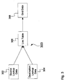
- FIG. 3 is a block diagram 300 in which source lookup data stored in table 302 and destination lookup data stored in table 304 is joined based upon the relationships defined in a link table 306.
- the link table sets forth the mapping illustrated by Entity Maps 204, 206 and 208 in FIG. 2. For example, if the source and destination lookup data is stored in a SQL database, this joining can be through a SQL query.
- the joined data is stored in table 308 as grid data and can comprise a plurality of data tables.
- the administrator may change the configuration of an Entity.
- Entity 1 for System 1 is of the following form: Subsequently, assume the administrator changes Entity 1 to include a city field such as:
- the dynamic user interface of the invention generates the modified XML string which is returned to engine 200.
- the new Entity format can be conveyed to System 2, or at least an indication provided to System 2 that the Entity is changed.
- FIG. 4 is a block diagram of a system specific data store configuration 400 in one specific exemplary embodiment.
- An integration system master table 402 includes a primary key (PK) associated with the System ID.
- PK primary key
- the actual system name is associated with a unique index, U2.
- Table 402 also contains other information such as display information, default configuration and XML configuration.
- Table 404 provides integration system entity information including entity type, the source schema name, the system schema name, publication information, etc. and includes a foreign key (FK1) which identifies a particular System ID.
- An integration entity configuration table 406 is keyed to a foreign key (FK1) and provides an entity identification node name to identify a particular node in the data store 400 and its configuration data.
- Integration entity map table 408 provides the mapping data used to map between two entities in two systems. Source and destination entities are identified with foreign keys.
- Table 410 provides specific mapping configuration data for a node in the data 400.
- Integration system map table 412 and integration system map configuration table 414 are used to map between two systems. They are linked to an overall integration master table 416.
- Integration system configuration table 418 maintains node configuration data for a system.
- integration entity instance table 420 identifies a particular entity and table 422 provides the link between entities.
- An archive table (not shown) can also be used to store historical data and track changes to the entity links.
- One embodiment of primary steps to generate and display the dynamic user interface of the invention are as follows:
- an XML configuration node is extracted from the appropriate system table set forth in FIG. 4. Based upon the extracted XML configuration node data, each tab group of the user interface is identified for the node (as shown in FIGS. 5 and 6). For each section in the tab group, and for each field in the section, the particular user interface type is determined. If lookup data is required, a system proxy is called which provides XML lookup data for the particular field, the appropriate user interface is created. In operation, input field of the dynamic user interface (pick list, button, etc.) is based upon the determined user interface type and any lookup data which was obtained. If the user interface is a list type (a dropdown list, table, etc.) each particular node is added from the XML lookup data.
- each tab group of the user interface is identified for the node (as shown in FIGS. 5 and 6). For each section in the tab group, and for each field in the section, the particular user interface type is determined. If lookup data is required, a system proxy is called which provides X
- the user interface type is a linked entity table
- a table generator routine is called in which all the linked entity records are loaded, the source system entities are loaded, and the destination system entities are loaded (for example through querying proxies). These record sets are then joined.
- dynamic HTML code is generated to link the appropriate system specific data and the appropriate user interface. The final page is assembled and passed to the browser.
- an XML node is received for the new data to be saved.
- the particular save type is determined (for example, integration, configuration or system default data) and the data value is saved into the appropriate configuration table shown in FIG. 4.
- an XML string is passed to the integration engine to create the appropriate link by populating the appropriate link instance in the data store 400 shown in FIG. 4.
- a system proxy is called for the appropriate system and the data is passed to the system using the appropriate interface technique.
- the pick list data can be obtained using any appropriate technique including hard coding the data store with system specific data or other input techniques.
- an automated technique can be used in which a server proxy is defined for each system and used to return pick list data for that system.
- the server proxy operates in accordance with a standardized interface.
- a retrieve pick list call can be made to a server proxy of the form:
- the config data can be, for example, one large XML string which is comprised of all of the data for a particular node.
- the string will contain data for at least one lookup node.
- the data can be generated using the appropriate query technique for a given system, for example by using a SQL query.
- the string is parsed to identify the lookup node and then a connection string is retrieved from the config data.
- the retrievePickList then returns the large XML string.
- This can be configured as appropriate for a particular system, for example by parsing out the server name and passing the entity to the appropriate server.
- the XML string is also updated to include the appropriate entity name used by the integration engine for a particular entity. In general, all of the configuration data is passed so that any desired data can be parsed from the string.
- the present invention provides a dynamic user interface for configuring business systems using an XML string generated from a system specific assembly.
- system specific assemblies can be formed for any system, and the integration engine can be used across multiple platforms.
- An interface to exchange data is implemented on each system in accordance with an interface specification.
- the integration engine can then query the interface and be used to populate the assembly. This allows the interface to be designed generically and the system data that is automatically retrieved is used to populate the assembly as desired.
- the XML code is used as a description of the user interface. This can be combined with a system interface to interrogate each system in the integration.
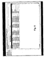
- FIG. 5 is a screen shot showing an example user interface in accordance with the present invention.
- a plurality of tabs are arranged vertically to allow an administrator to select a particular system. Within the selected system, specific tabs are arranged horizontally to allow the configuration and mapping of entities.
- Sales Document configuration is selected which allows the administrator to select default sales document type identification, how a credit limit is handled, what order types are to be published from the system and what invoices are to be published.
- the page also allows the administrator to select how sales documents are to be batched, the frequency for how sales documents are batched, when sales documents are batched and how inventory transactions are handled.
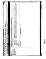
- FIG. 6 shows a horizontal tab selected which graphically illustrates the mapping of payment terms between systems (the "Mapped Entities").
- Mapped Entities various payment term values from one system are mapped to or linked to payment term values in another system.
- a dropdown list allows a system administrator to select from other field names. Note that this table can also be viewed from the destination system perspective in which the source fields and destination fields are reversed.
- FIG. 8 shows one embodiment of the dialog of the user interface which allows an administrator to select which entities are published. Note that if one entity is not published, another entity may also not be published. For example, if the address entity is not published, the publishing of the orders entity is no longer valid and so the orders entity will also not be published.
- one example user interface configuration XML instance for such a dynamic user interface is as follows:
- Tables of FIG. 4 can be in accordance with any desired format.
- the following are sample configuration node records for a system-level configuration:
- the present invention provides a dynamic user interface for configuring the relationship between systems.
- the system provides for the storage of an XML layout of the user interface on an application service provider (ASP) page.
- the user interface can comprise a plurality of tabs with various user interface inputs located under each tab.
- Each of the inputs of the user interface input can be customized as a text box, label, checkbox, dropdown, table list, etc.
- each object can be customized as to the target of its action.
- data can be targeted at the configuration data stored as integration meta data, default data passed to the integrated systems, or the creation of linked records in the integration itself.
- the present invention provides a combination of a markup language description (such as XML) of the user interface and a system specific assembly which is used to manage certain retrieval and configuration methods.
- the system specific assembly can be generated using any appropriate technique including automated techniques using system proxies. This provides a single interface to manage integration between multiple systems.
- the user interface generator can be hosted in a web application.
- the user interface is designed to be similar to the user interface used to configure the systems being integrated.
- the integration engine includes a set of tables that contain a list of the systems that are integrated, the unique entities within those systems that are integrated, and the attributes of each of those entities. Each of these tables has a text field containing the user interface configuration in an XML string. Further, each of the tables also has a joined one-to-many table that contains a list of configuration nodes that may be used by the integration itself, or passed on to that entity every time a document is posted to it. Further, each integrated system can provide a system specific assembly that implements a specific interface. This interface controls retrieving entity schema and information, retrieving pick list data (for example as XML), a generic query used to return data (for example as XML) and a method to control the publication of data, for example.
- the XML configuration field for each of the systems is passed to a main component of the user interface generator.
- the generator then proceeds to read each node and generate the appropriate user interface control. If the configuration is for a specific entity-to-entity mapping, an entry can be made in the XML configuration data that defines the source system, source entity and destination entity.
- the engine will then retrieve the appropriate configuration from that map, generate the appropriate user interface information and return the user interface information inside the main user interface XML string.
- the user interface integration engine Upon receiving this data set, the user interface integration engine loops through, each node and determines what type of save operation should be performed. If the save is for integration specific data, the data is passed to the integration platform to save in a storage operation. If the data to be saved is for creating a new link between entities, then that data is passed to another components in the integration platform that creates those links. Finally, if the data to be saved is system default data, it is stored in the meta data to be passed to the appropriate document.
- a system specific assembly is used by a user interface generator to generate a dynamic user interface.
- the system specific assembly is a set of information which describes a particular system to be integrated. New systems can be added to the integration by simply adding new assemblies for each system.
- the assembly can be individually coded or can be automatically generated using a proxy through a common interface.
- the interface illustratively utilizes XML as a descriptor, however, other techniques can be used such as XSL (extensible stylesheet language), etc.
Landscapes
- Engineering & Computer Science (AREA)
- Business, Economics & Management (AREA)
- Strategic Management (AREA)
- Entrepreneurship & Innovation (AREA)
- Human Resources & Organizations (AREA)
- Operations Research (AREA)
- Economics (AREA)
- Marketing (AREA)
- Data Mining & Analysis (AREA)
- Quality & Reliability (AREA)
- Tourism & Hospitality (AREA)
- Physics & Mathematics (AREA)
- General Business, Economics & Management (AREA)
- General Physics & Mathematics (AREA)
- Theoretical Computer Science (AREA)
- Information Retrieval, Db Structures And Fs Structures Therefor (AREA)
- User Interface Of Digital Computer (AREA)
- Stored Programmes (AREA)
Applications Claiming Priority (2)
| Application Number | Priority Date | Filing Date | Title |
|---|---|---|---|
| US384343 | 1982-06-02 | ||
| US10/384,343 US7269795B2 (en) | 2003-03-07 | 2003-03-07 | Dynamically generated user interface for business application integration |
Publications (2)
| Publication Number | Publication Date |
|---|---|
| EP1465062A2 true EP1465062A2 (fr) | 2004-10-06 |
| EP1465062A3 EP1465062A3 (fr) | 2006-12-27 |
Family
ID=32850501
Family Applications (1)
| Application Number | Title | Priority Date | Filing Date |
|---|---|---|---|
| EP04003311A Ceased EP1465062A3 (fr) | 2003-03-07 | 2004-02-13 | Interface d'utilisateur générée dynamiquement pour intégration d'application d'affaires |
Country Status (2)
| Country | Link |
|---|---|
| US (1) | US7269795B2 (fr) |
| EP (1) | EP1465062A3 (fr) |
Cited By (1)
| Publication number | Priority date | Publication date | Assignee | Title |
|---|---|---|---|---|
| EP1699009A1 (fr) * | 2005-03-04 | 2006-09-06 | Microsoft Corporation | Mise à jour automatique de l'interface utilisateur dans des procédés commerciaux |
Families Citing this family (29)
| Publication number | Priority date | Publication date | Assignee | Title |
|---|---|---|---|---|
| US7356482B2 (en) | 1998-12-18 | 2008-04-08 | Alternative Systems, Inc. | Integrated change management unit |
| US20050005259A1 (en) * | 2003-03-14 | 2005-01-06 | Infowave Software, Inc. | System and method for communication and mapping of business objects between mobile client devices and a plurality of backend systems |
| US7516412B1 (en) * | 2003-05-23 | 2009-04-07 | Nvidia Corporation | Method and apparatus for content-based rendering of user interfaces |
| JP2006526828A (ja) * | 2003-06-05 | 2006-11-24 | スイス リインシュアランス カンパニー | 均一な装置無依存型グラフィカル・ユーザー・インターフェースの生成方法およびターミナル |
| US20050108024A1 (en) * | 2003-11-13 | 2005-05-19 | Fawcett John Jr. | Systems and methods for retrieving data |
| US7404185B2 (en) * | 2003-12-02 | 2008-07-22 | International Business Machines Corporation | Method and apparatus of adaptive integration activity management for business application integration |
| JP5032842B2 (ja) * | 2004-03-26 | 2012-09-26 | パナソニック株式会社 | 表示処理装置及び表示処理方法 |
| US20070050420A1 (en) * | 2005-08-30 | 2007-03-01 | Sankruthi Anand D | Method and apparatus for transferring data between databases |
| US7971145B2 (en) * | 2006-05-22 | 2011-06-28 | Sap Ag | Systems and methods for adapting service interface behaviors |
| US20080028328A1 (en) * | 2006-07-31 | 2008-01-31 | Sap Ag | System and method to dynamically change object data patterns |
| US9798784B1 (en) * | 2008-08-22 | 2017-10-24 | Salesforce.Com, Inc. | System, method and computer program product for defining custom junction objects in an on-demand database service |
| US20090150795A1 (en) * | 2007-12-11 | 2009-06-11 | Microsoft Corporation | Object model and user interface for reusable map web part |
| US20090157734A1 (en) * | 2007-12-18 | 2009-06-18 | Zubair Khan | Dynamically generated mvc based user interface |
| US7912809B2 (en) * | 2007-12-30 | 2011-03-22 | Gregory Shteyngarts | Data management system for manufacturing enterprise and related methods |
| EP2107807A1 (fr) * | 2008-04-04 | 2009-10-07 | Irdeto Access B.V. | Système d'accès conditionnel et carte intelligente pour une utilisation dans le système d'accès conditionnel |
| DE102009000553B4 (de) * | 2009-02-02 | 2012-12-06 | Schott Ag | Aktive Optokeramiken mit kubischer Kristallstruktur, deren Herstellung und Verwendungen |
| US8132109B2 (en) * | 2009-05-15 | 2012-03-06 | International Business Machines Corporation | Webpage magnifier/formatter using CSS properties and cursor/mouse location |
| US20110209049A1 (en) * | 2010-02-23 | 2011-08-25 | Microsoft Corporation | Data binding for a web-based visual representation of a structured data solution |
| US9600512B2 (en) * | 2010-02-25 | 2017-03-21 | Salesforce.Com, Inc. | Systems and methods for implementing customized drop-down menus |
| US9460415B2 (en) * | 2011-11-10 | 2016-10-04 | Sap Se | Determining semantic information of business applications |
| US20140059498A1 (en) * | 2012-08-27 | 2014-02-27 | Microsoft Corporation | User interface display of anchor tiles for related entities |
| US9280327B2 (en) | 2012-09-07 | 2016-03-08 | NIIT Technologies Ltd | Simplifying development of user interfaces of applications |
| US8886671B1 (en) | 2013-08-14 | 2014-11-11 | Advent Software, Inc. | Multi-tenant in-memory database (MUTED) system and method |
| US10484488B2 (en) | 2014-11-24 | 2019-11-19 | C-Labs Corporation | Method for dynamic and automatic creation of user interfaces |
| US10296504B2 (en) | 2015-12-15 | 2019-05-21 | Successfactors, Inc. | Graphical user interface for querying relational data models |
| US10552526B2 (en) | 2015-12-15 | 2020-02-04 | Successfactors, Inc. | Graphical user interface for field calculations |
| US10409436B2 (en) * | 2015-12-15 | 2019-09-10 | Successfactors, Inc. | Graphical user interface for qualifying navigations through relational data models |
| CN113010154B (zh) * | 2019-12-19 | 2024-05-14 | 中国科学院沈阳自动化研究所 | 基于动态加载的二级数据管理界面可视化开发配置方法 |
| CN115048177B (zh) * | 2022-08-15 | 2022-11-04 | 成都中科合迅科技有限公司 | 基于自定义容器完成业务场景的动态配置方法 |
Family Cites Families (5)
| Publication number | Priority date | Publication date | Assignee | Title |
|---|---|---|---|---|
| US6407753B1 (en) * | 1999-05-04 | 2002-06-18 | International Business Machines Corporation | System and method for integrating entities via user-interactive rule-based matching and difference reconciliation |
| US6662237B1 (en) * | 1999-06-24 | 2003-12-09 | Contivo, Inc. | System for documenting application interfaces and their mapping relationship |
| US6816865B2 (en) * | 2001-04-18 | 2004-11-09 | International Business Machines Corporation | Process for data driven application integration for B2B |
| US20030043192A1 (en) | 2001-08-31 | 2003-03-06 | Schlumberger Technology Corporation | Dynamically modifiable user interface |
| US20030195765A1 (en) * | 2002-04-10 | 2003-10-16 | Mukesh Sehgal | Data exchange method and system |
-
2003
- 2003-03-07 US US10/384,343 patent/US7269795B2/en not_active Expired - Fee Related
-
2004
- 2004-02-13 EP EP04003311A patent/EP1465062A3/fr not_active Ceased
Cited By (1)
| Publication number | Priority date | Publication date | Assignee | Title |
|---|---|---|---|---|
| EP1699009A1 (fr) * | 2005-03-04 | 2006-09-06 | Microsoft Corporation | Mise à jour automatique de l'interface utilisateur dans des procédés commerciaux |
Also Published As
| Publication number | Publication date |
|---|---|
| US20040176967A1 (en) | 2004-09-09 |
| EP1465062A3 (fr) | 2006-12-27 |
| US7269795B2 (en) | 2007-09-11 |
Similar Documents
| Publication | Publication Date | Title |
|---|---|---|
| EP1465062A2 (fr) | Interface d'utilisateur générée dynamiquement pour intégration d'application d'affaires | |
| US6523042B2 (en) | System and method for translating to and from hierarchical information systems | |
| US7890922B2 (en) | System and article of manufacture for integration of data management operations into a workflow system | |
| US7634478B2 (en) | Metadata driven intelligent data navigation | |
| US7805341B2 (en) | Extraction, transformation and loading designer module of a computerized financial system | |
| KR101176642B1 (ko) | 컴퓨터 플랫폼에 대한 프로그래밍 인터페이스 | |
| US7194485B2 (en) | Mapping XML schema components to qualified java components | |
| US20040093559A1 (en) | Web client for viewing and interrogating enterprise data semantically | |
| US7320003B2 (en) | Method and system for storing and retrieving document data using a markup language string and a serialized string | |
| US20050091231A1 (en) | System and method for storing and retrieving XML data encapsulated as an object in a database store | |
| US7360215B2 (en) | Application interface for analytical tasks | |
| JP4571636B2 (ja) | サービス指向ビジネスフレームワークのサービス管理 | |
| US7370028B2 (en) | Method of and system for providing namespace based object to XML mapping | |
| US20050203760A1 (en) | Project time and expense | |
| MXPA00007085A (es) | Sistema de integracion de aplicacion de empresa distribuido extensible. | |
| JP2006528800A (ja) | 自己記述型ビジネスオブジェクト | |
| US20050234886A1 (en) | Report designer tool and method | |
| US7099727B2 (en) | Knowledge repository system for computing devices | |
| US20090024655A1 (en) | Scheme-Based Identifier | |
| JP2008511936A (ja) | データ・システムにおける意味識別のための方法およびシステム | |
| US20070067323A1 (en) | Fast file shredder system and method | |
| US20100250621A1 (en) | Financial-analysis support apparatus and financial-analysis support method | |
| US7694307B2 (en) | Analytical task invocation | |
| US20060064465A1 (en) | Advanced message mapping with sub-object key mapping | |
| Seng et al. | An intelligent XML-based multidimensional data cube exchange |
Legal Events
| Date | Code | Title | Description |
|---|---|---|---|
| PUAI | Public reference made under article 153(3) epc to a published international application that has entered the european phase |
Free format text: ORIGINAL CODE: 0009012 |
|
| AK | Designated contracting states |
Kind code of ref document: A2 Designated state(s): AT BE BG CH CY CZ DE DK EE ES FI FR GB GR HU IE IT LI LU MC NL PT RO SE SI SK TR |
|
| AX | Request for extension of the european patent |
Extension state: AL LT LV MK |
|
| PUAL | Search report despatched |
Free format text: ORIGINAL CODE: 0009013 |
|
| AK | Designated contracting states |
Kind code of ref document: A3 Designated state(s): AT BE BG CH CY CZ DE DK EE ES FI FR GB GR HU IE IT LI LU MC NL PT RO SE SI SK TR |
|
| AX | Request for extension of the european patent |
Extension state: AL LT LV MK |
|
| 17P | Request for examination filed |
Effective date: 20070619 |
|
| AKX | Designation fees paid |
Designated state(s): AT BE BG CH CY CZ DE DK EE ES FI FR GB GR HU IE IT LI LU MC NL PT RO SE SI SK TR |
|
| 17Q | First examination report despatched |
Effective date: 20071012 |
|
| STAA | Information on the status of an ep patent application or granted ep patent |
Free format text: STATUS: THE APPLICATION HAS BEEN REFUSED |
|
| 18R | Application refused |
Effective date: 20130216 |