EP1467174A2 - Dispositif indicateur pour jauge à cadran - Google Patents
Dispositif indicateur pour jauge à cadran Download PDFInfo
- Publication number
- EP1467174A2 EP1467174A2 EP04008783A EP04008783A EP1467174A2 EP 1467174 A2 EP1467174 A2 EP 1467174A2 EP 04008783 A EP04008783 A EP 04008783A EP 04008783 A EP04008783 A EP 04008783A EP 1467174 A2 EP1467174 A2 EP 1467174A2
- Authority
- EP
- European Patent Office
- Prior art keywords
- dial
- dial face
- area indicator
- face
- gauge
- Prior art date
- Legal status (The legal status is an assumption and is not a legal conclusion. Google has not performed a legal analysis and makes no representation as to the accuracy of the status listed.)
- Granted
Links
Images


Classifications
-
- G—PHYSICS
- G01—MEASURING; TESTING
- G01D—MEASURING NOT SPECIALLY ADAPTED FOR A SPECIFIC VARIABLE; ARRANGEMENTS FOR MEASURING TWO OR MORE VARIABLES NOT COVERED IN A SINGLE OTHER SUBCLASS; TARIFF METERING APPARATUS; MEASURING OR TESTING NOT OTHERWISE PROVIDED FOR
- G01D13/00—Component parts of indicators for measuring arrangements not specially adapted for a specific variable
- G01D13/02—Scales; Dials
- G01D13/04—Construction
- G01D13/10—Construction with adjustable scales; with auxiliary scales, e.g. vernier
-
- G—PHYSICS
- G01—MEASURING; TESTING
- G01B—MEASURING LENGTH, THICKNESS OR SIMILAR LINEAR DIMENSIONS; MEASURING ANGLES; MEASURING AREAS; MEASURING IRREGULARITIES OF SURFACES OR CONTOURS
- G01B3/00—Measuring instruments characterised by the use of mechanical techniques
- G01B3/22—Feeler-pin gauges, e.g. dial gauges
Definitions
- the present invention relates to a dial-display measuring tool using a dial-type display.
- a dial gauge which is one of such tools, is a dimension measuring tool to read a dimension of a workpiece based on a rotation amount of its pointer.
- the dial gauge is widely used as it may be attached to a measurement stand or installed into a jig or a testing tool, and it has a large variety to serve different applications.
- a one-revolution dial gauge is useful for comparative measurements since users rarely make a mistake in reading the rotation amount of the pointer.
- Fig. 8 is an exploded perspective view showing the example of the conventional one-revolution dial gauge.
- the one-revolution dial gauge 100 includes a gauge body 10, a dial face 130 provided on a base plate 12 of the gauge body 10 with a leaf spring 7 interposed therebetween, a pointer 5 attached to the centre of the gauge body 10, and a bezel 160 covering the dial face 130 and the pointer 5.
- the gauge body 10 includes a cylindrical casing and axially slidably supports a spindle 2 passing through the gauge body 10, the spindle 2 having a contact point 21 at an end thereof.
- the spindle 2 and the contact point 21 constitute a probe.
- the bezel 160 is attached to the gauge body 10 to cover the dial face 130 and the pointer 5.
- Fig. 9 is an enlarged view showing the dial face 130 in the conventional art.
- the dial face 130 has graduations 133 arranged at regular circumferential intervals and a dead zone 134 indicating an area where measurement accuracy is not assured.
- the dial face 130 has a notch 131 while the bezel 160 has a projection 162 at a position matching the notch 131.
- the projection 162 is fitted into the notch 131 so that the dial face 130 is fixed to the bezel 160 not to be rotated separately.
- the leaf spring 7 biases the dial face 130 toward the bezel 160 for avoiding errors in reading measurements due to a misalignment of the dial face 130.
- a pointer attachment process which is a process to attach the pointer 5 onto a pointer shaft 11, included in a production process of the one-revolution dial gauge 100 is descried with reference to Fig. 10.
- the leaf spring 7 interposed between the dial face 130 and the base plate 12 keeps the dial face 130 shaky and unstable. Because of this, in positioning the dial face 130, a temporary bezel 8 without a cover plate is set on the gauge body 10. Then a projection 81, which is formed in advance in the temporary bezel 8, is fitted into the notch 131 of the dial face 130 to fix the dial face 130, and thereafter the pointer 5 is attached. Once the pointer 5 is attached, the temporary bezel 8 is removed and the bezel 160 is set thereon.
- An object of the present invention is to provide a dial-display measuring tool that can prevent measurement errors when a dial face is rotated and can share its components with other standard measuring tools.
- a dial-display measuring tool includes: a gauge body; a probe attached to the gauge body; a pointer that points a measurement value in response to a movement of the probe and is attached to the gauge body; a dial face showing graduations of measurement values; and an area indicator showing a predetermined range of the graduations, the dial face and the area indicator being independently turnable and separately formed.
- the dial face and the area indicator are formed separately to be independently turnalbe, the area indicator is not rotated even when the dial face is rotated. With this arrangement, the area indicator can indicate a correct area regardless of the rotated position of the dial face, thereby preventing measurement errors. Further, since the area indicator is not included in the dial face, the dial face is the same type of standard dial faces and can be used as a standard dial face.
- a bezel is turnably attached to the gauge body, and the area indicator is attached to the gauge body.
- the area indicator is attached to the gauge body and the dial face is attached to the bezel. Since the dial face is fixed to the bezel, a leaf spring, which makes the dial face unstable, is not used at a pointer attachment process and hence a temporary bezel is also unnecessary. Therefore, the pointer can be easily attached.
- a view hole is formed substantially at the center of the dial face to show an approximate center of the area indicator therethrough, and an edge of the area indicator is extended across a rim of the view hole to cover a part of a surface of the dial face.
- the area indicator since a part of the area indicator covers a part of the surface of the dial face, the area indicator has an enlarged visible size and can be easily recognized, thereby preventing errors in reading the graduations such as oversight of the area indicator.
- the dial face is made of transparent material.
- the area indicator is shown without being hidden by the dial face. Therefore, the area indicator is visible even with the dial face, thereby preventing measurement errors due to oversight of the area indicator and the like.
- the dial face is a transparent cover plate provided on an upper face of the bezel.
- the dial face is the transparent cover plate of the bezel, the area indicator is shown without being hidden by the dial face, thereby preventing measurement errors due to mistakes in reading the area indicator. Further, since the dial face serves as the cover plate, the number of components can be reduced.
- the dial-display measuring tool of the present invention is a one-revolution dial gauge including: the gauge body; the contact point; the pointer; the dial face; and the area indicator, and a dead zone indicating an area where measurement accuracy is not assured is shown on the area indicator.
- the one-revolution dial gauge according to the present invention can obtain the above-mentioned advantages, prevent human mistakes and errors, and share its components with other standard dial gauges.
- a one-revolution dial gauge is similar to the one in the conventional art shown in Figs. 8 to 10, and components identical to or corresponding to those in the conventional art are denoted by the same reference numerals to omit or simplify descriptions thereof.
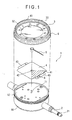
- Fig. 1 is an exploded perspective view showing the one-revolution dial gauge, which is a dial-display measuring tool, in the first embodiment.
- the one-revolution dial gauge 1 includes a gauge body 10, an area indicator 4 that is a substantially rectangular thin plate and provided on a base plate 12 on the upper side of the gauge body 10, a pointer 5 attached onto and fixed to the center of the gauge body 10, a bezel 6 rotatably attached to the gauge body 10, and a dial face 3 attached to the bezel 6.
- a pointer shaft 11 is formed at the center of the gauge body 10 to be perpendicular to the base plate 12. The pointer shaft 11 rotates in response to a displacement of a spindle 2. By fixing the pointer 5 to the pointer shaft 11, the displacement of the spindle 2 can be converted to a rotating angle of the pointer 5.
- the area indicator 4 is made of lightweight metal material such as stainless and aluminum. A pair of opposite sides of the area indicator 4 respectively have attachment pieces 43, which are fixed to the base plate 12 of the gauge body 10 with a screw or the like, so that the area indicator 4 is attached to the gauge body 10.
- a substantially triangular dead zone 41 is formed with two lines extending radially from the center of the gauge body 10 with a predetermined contact angle and a line orthogonal to the axial direction of the spindle 2, the dead zone 41 indicating an area where measurements are not assured in measurement works.
- the area indicator 4 has a shaft hole 42 at the center thereof, the shaft hole 42 having a diameter slightly larger than that of the pointer shaft 11.
- the pointer 5 is attached onto the pointer shaft 11 passing through the shaft hole 42.
- Fig. 2 is an enlarged view showing the dial face 3.
- the dial face 3 has graduations 33 at regular circumferential intervals throughout the circumference thereof.
- the dial face 3 is the same type of a dial face of measuring tools that require graduations throughout the circumference thereof, such as a dial face of a standard dial gauge capable of plural revolutions.
- the dial face 3 has a view hole 32 with a relatively large diameter at the center thereof, and hence the area indicator 4 positioned under the dial face 3 is visible through the view hole 32.
- the dial face 3 is made of lightweight and high-strength material such as stainless and aluminum, and fixed to an inner wall of the bezel 6 by caulking.
- the bezel 6 has a cover plate 61 on the upper surface thereof.
- the cover plate 61 is made of transparent material, and hence the area indicator 4 and the pointer 5 arranged inside are visible.
- the bezel 6 is tumably attached along a circumference of the base plate 12 of the gauge body 10.
- Fig. 3 is an illustration showing a part of the pointer attachment process, which is a process to attach the pointer 5 onto the pointer shaft 11, in a production process of the one-revolution dial gauge 1.
- the pointer 5 is attached onto and fixed to the pointer shaft 11 along a reference line A representing a pointer attachment position. Since the area indicator 4 is fixed to the gauge body 10 and the dial face 3 is fixed to the bezel 6, the leaf spring 7 and the temporary bezel 8 in the conventional art are unnecessary.
- a user places a contact point 21 to abut on a workpiece and rotates or moves the workpiece.
- a displacement of the spindle 2 thus found is converted to a rotation amount in the gauge body 10 and transmitted to the pointer 5, so that the user reads a graduation 33 pointed by the pointer 5 to obtain a measurement value.
- the user rotates the bezel 6 to locate a graduation "0" on a position pointed by the pointer 5 at the start.
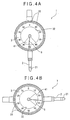
- FIG. 4A is a plan view showing the one-revolution dial gauge 1 in which the dial face 3 of the one-revolution dial gauge 1 according to the first embodiment is set so that the graduation "0" is aligned along the axial direction of the spindle 2
- Fig. 4B is a plan view showing the one-revolution dial gauge 1 in which the dial face 3 of the dial gauge 1 of the first embodiment is rotated from the position shown in Fig. 4A so that the graduation "0" is moved.
- the dead zone since the dead zone is fixed to the dial face, the dead zone is rotated together if the dial face is rotated.
- the first embodiment as shown in Figs.
- the area indicator 4 is fixed to the gauge body 10 and hence the dead zone 41 is also fixed thereto.
- the dead zone 41 which indicates the area where the accuracy is not assured when the pointer 5 is rotated more than a predetermined amount relative to the gauge body 10, is provided in relation to the gauge body 10 and not related to the rotation of the dial face 3. With this arrangement, the dead zone 41 always indicates the correct area even when the dial face 3 is rotated.
- the dial-display measuring tool according to the first embodiment has the following advantages.
- a second embodiment of the present invention will be descried with reference to Figs. 5A and 5B.
- the area indicator 4 is provided on the gauge body 10 and the area indicator 4 is visible only through the view hole 32 of the dial face 3.
- the area indicator 4 is improved to enlarge the visible size of the dead zone for easier recognition.
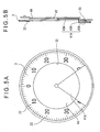
- Fig. 5A is a front view showing a one-revolution dial gauge in the second embodiment
- Fig. 5B is a sectional view showing the center of the one-revolution dial gauge.
- an area indicator 4A is fixed to a gauge body 10
- a dial face 3 is fixed to a bezel 6.
- a dead zone 41A of the area indicator 4A are integrally formed with a flat portion 43A, a standing portion 44A formed at an end of the flat portion 43A and extended toward a rim of the view hole 32, and a cover portion 45A extended radially from the standing portion 44A to cover a part of a dial face 3. Since the dead zone 41A covers an upper surface of the dial face 3, the dead zone 41 A on the dial face 3 is visually recognizable.
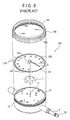
- FIG. 6A is a front view showing a one-revolution dial gauge in the third embodiment
- Fig. 6B is a sectional view showing the center of the one-revolution dial gauge in the third embodiment.
- configuration of a dial face 3B of the one-revolution dial gauge 1 of the third embodiment is different from that of the first embodiment although other components are the same.
- the dial face 3B is made of transparent material such as glass and transparent plastic, and hence an area indicator 4 provided under the dial face 3B is visible.
- the following advantages can be obtained in addition to the advantages (1) and (2) of the first embodiment.
- FIG. 7A is a front view showing the one-revolution dial gauge in the fourth embodiment
- Fig. 7B is a sectional view showing the center of the one-revolution dial gauge in the fourth embodiment.
- the one-revolution dial gauge 1 includes a cover plate 61 C covering an upper surface of a bezel 6C and serving as a dial face, the cover plate 61 C having graduations 63C inscribed or printed on the backside thereof. Since the graduations 63C are formed on the backside of the cover plate 61C, the graduations do not fade while keeping good appearance.
- the cover plate 61 C is made of transparent plastic, glass or the like, and hence a pointer 5 and a dead zone 41 of an area indicator 4 located inside are visible from the outside.
- the dial face 3 is fixed to the inner wall of the bezel 6 by caulking, but the configuration is not limited thereto. That is, as long as the dial face 3 is attached to the bezel 6 and fixed, any method may be used for fixing it. For instance, if a positioning portion is formed on the bezel 6, the dial face 3 may be fixed thereto by bonding or with a screw.
- the dial face 3 and the area indicator 4 are made of metal such as stainless steel, but it may be made of other materials.
- the dial face 3 and the area indicator 4 may be made of synthetic resin, ceramics or the like other than metal.
- materials such as synthetic resin with thermoplasticity may be deformed if used under high temperature, graduations become incorrect. For this reason, the material should be selected depending on use conditions.
- the material used for the dead zone 41 A of the area indicator 4A is not specified, but it may be translucent synthetic resin or the like or may be metal material. If a translucent film with transparency is used, the dead zone 41A can cover the upper surface of the dial face without troublesome processing required in the case of metal. However, if the materials with thermoplasticity described above are used, the dead zone cannot indicate the correct area due to deformation. For this reason, the material should be selected depending on use conditions.
- the area indicator 4 is a substantially rectangular thin plate, but it may have a different shape. As long as the area indicator 4 can be attached to the base plate 12 of the gauge body 10 and has a size to clearly show the dead zone 41, the shape and the size are not limited. For instance, an area indicator having a circular shape to cover the base plate 12 or the one having only the size of the dead zone may be applicable.
- the area indicator 4 is positioned under the dial face 3, but the position is not limited thereto.
- the area indicator may be positioned over the dial face.
- only the dead zone may be fixed to the cylinder. That is, as long as the dead zone 41 is fixed to the dial face 3 and a relative position of the dead zone 41 and the gauge body 10 is unchanged, the positional relationship between the dial face 3 and the area indicator 4 is not limited.
- the dial face 3 is substituted by the graduations formed on the cover plate 61C.
- the area indicator 4 may be substituted by this dead zone.
- the dial face 3 must be made of transparent material. Forming the graduations on the cover plate 61C and the dead zone on the base plate 12 can further reduce the number of components.
- the dial gauge is cited as an example of the dial-display measuring tool, but the tool is not limited thereto.
- it may be a micrometer equipped with a dial gauge that can measure the outer diameter of a workpiece with high accuracy, or may be a dial depth gauge that is a depth gauge for measuring the height or the depth of a workpiece using a dial display. That is, any dial-display measuring tools are applicable as long as a displacement of a contact point or a measurement value read by the contact point etc. is converted to a rotation amount and a pointer points the measurement value in response to the rotation amount.
Landscapes
- Physics & Mathematics (AREA)
- General Physics & Mathematics (AREA)
- Length-Measuring Instruments Using Mechanical Means (AREA)
Applications Claiming Priority (2)
| Application Number | Priority Date | Filing Date | Title |
|---|---|---|---|
| JP2003108082A JP4399186B2 (ja) | 2003-04-11 | 2003-04-11 | ダイヤル表示式測定器 |
| JP2003108082 | 2003-04-11 |
Publications (3)
| Publication Number | Publication Date |
|---|---|
| EP1467174A2 true EP1467174A2 (fr) | 2004-10-13 |
| EP1467174A3 EP1467174A3 (fr) | 2006-06-07 |
| EP1467174B1 EP1467174B1 (fr) | 2007-09-05 |
Family
ID=32866800
Family Applications (1)
| Application Number | Title | Priority Date | Filing Date |
|---|---|---|---|
| EP04008783A Expired - Lifetime EP1467174B1 (fr) | 2003-04-11 | 2004-04-13 | Dispositif indicateur pour jauge à cadran |
Country Status (5)
| Country | Link |
|---|---|
| US (1) | US6925727B2 (fr) |
| EP (1) | EP1467174B1 (fr) |
| JP (1) | JP4399186B2 (fr) |
| CN (1) | CN1536586B (fr) |
| DE (1) | DE602004008691T2 (fr) |
Cited By (1)
| Publication number | Priority date | Publication date | Assignee | Title |
|---|---|---|---|---|
| CN113532235A (zh) * | 2021-07-30 | 2021-10-22 | 江西昌河航空工业有限公司 | 一种o型密封圈中心内径的测量工具及方法 |
Families Citing this family (14)
| Publication number | Priority date | Publication date | Assignee | Title |
|---|---|---|---|---|
| US20050243655A1 (en) * | 2004-04-19 | 2005-11-03 | Mccutcheon Shawn | Programmable analog display timer system |
| JP2006008729A (ja) * | 2004-06-22 | 2006-01-12 | Denki Kagaku Kogyo Kk | 光硬化性樹脂組成物とその硬化体の製造方法 |
| US8904661B1 (en) * | 2013-12-12 | 2014-12-09 | Rulersmith Ip, Inc. | Transparent measuring device with enhanced viewing windows |
| EP3177895B1 (fr) * | 2014-08-07 | 2019-10-09 | Asco Sas | Dispositif indicateur, notamment manomètre |
| JP2017110979A (ja) | 2015-12-15 | 2017-06-22 | 株式会社ミツトヨ | 測定器 |
| US10753720B2 (en) * | 2017-06-20 | 2020-08-25 | Kenneth D. Schultz | End play measurement apparatus for linear actuators |
| JP7165601B2 (ja) * | 2019-02-28 | 2022-11-04 | 株式会社ミツトヨ | ゲージ検査治具及びゲージ検査機 |
| JP1650569S (fr) * | 2019-06-10 | 2020-01-20 | ||
| JP1648124S (fr) * | 2019-06-10 | 2019-12-16 | ||
| JP1650841S (fr) * | 2019-06-10 | 2020-01-20 | ||
| JP7161077B1 (ja) | 2021-07-05 | 2022-10-25 | 光精工株式会社 | 表示カバー |
| CN115307515A (zh) * | 2022-07-25 | 2022-11-08 | 云南浩鑫铝箔有限公司 | 铝箔卷表面热鼓检测装置及检测方法 |
| US12553747B2 (en) | 2023-12-20 | 2026-02-17 | Mitutoyo Corporation | Measuring instrument with arc encoder tracks |
| US12553746B2 (en) | 2023-12-20 | 2026-02-17 | Mitutoyo Corporation | Measuring instrument with linear encoder tracks and arc motion |
Family Cites Families (22)
| Publication number | Priority date | Publication date | Assignee | Title |
|---|---|---|---|---|
| DE391564C (de) * | 1921-06-19 | 1924-03-08 | Kienzle Uhrenfabriken Act Ges | Messuhr mit Zifferblatt und ueber diesem einstellbarer Blende |
| US1723390A (en) * | 1928-05-26 | 1929-08-06 | Fed Products Corp | Cover plate for measuring instruments |
| US1966424A (en) * | 1928-09-12 | 1934-07-17 | Ames Warren | Gauge |
| US2501033A (en) * | 1944-06-26 | 1950-03-21 | William E Denison | Indicator |
| US2771684A (en) * | 1952-07-28 | 1956-11-27 | Stromberg Tage Alfred | Improvements in measuring instruments |
| US2834115A (en) * | 1953-07-22 | 1958-05-13 | Walter H Bachmann | Dial indicator mechanism |
| US2707931A (en) * | 1954-02-12 | 1955-05-10 | Standard Gage Co Inc | Tolerance marker for dial indicator gages |
| DE1090870B (de) * | 1959-05-14 | 1960-10-13 | August Steinmeyer | Abdeckung fuer Messuhren |
| US3046931A (en) * | 1961-02-08 | 1962-07-31 | Ametek Inc | Adjustable graduations for instrument dial |
| US3890716A (en) * | 1970-08-27 | 1975-06-24 | Donald Hatch | Vernier indicator |
| US3664292A (en) * | 1970-12-02 | 1972-05-23 | Ritchie & Sons Inc E S | Magnetic compass tack heading indicator |
| US3721010A (en) * | 1971-02-08 | 1973-03-20 | H Ristow | Dial indicator gage |
| US4204334A (en) * | 1978-10-06 | 1980-05-27 | Cruz Luis B Dela | Precision gravity responsive angle indicator |
| CH634434A5 (fr) * | 1979-12-14 | 1983-01-31 | Far Fab Assortiments Reunies | Glace pour instrument de mesure. |
| JPH032801Y2 (fr) * | 1981-01-08 | 1991-01-25 | ||
| US4527336A (en) * | 1982-07-02 | 1985-07-09 | Mitutoyo Mfg. Co., Ltd. | Displacement measuring instrument |
| JPS5966103U (ja) * | 1982-10-25 | 1984-05-02 | トヨタ自動車株式会社 | ダイヤルゲ−ジ |
| JPS6234241A (ja) | 1985-08-08 | 1987-02-14 | Mitsubishi Electric Corp | 計算機のcpu負荷予測方式 |
| US4899453A (en) * | 1988-09-27 | 1990-02-13 | The United States Of America As Represented By The Secretary Of The Army | Compass with LED illumination |
| US5276976A (en) * | 1992-09-15 | 1994-01-11 | Hawkes Hollis D | Indicator tip turret |
| US5682682A (en) * | 1996-04-25 | 1997-11-04 | Federal Products Co. | Dial indicator with crowned gear |
| JP3530809B2 (ja) | 2000-08-01 | 2004-05-24 | 株式会社ミツトヨ | 所定回転未満ダイヤルゲージ |
-
2003
- 2003-04-11 JP JP2003108082A patent/JP4399186B2/ja not_active Expired - Fee Related
-
2004
- 2004-04-07 US US10/819,232 patent/US6925727B2/en not_active Expired - Lifetime
- 2004-04-12 CN CN2004100343629A patent/CN1536586B/zh not_active Expired - Lifetime
- 2004-04-13 EP EP04008783A patent/EP1467174B1/fr not_active Expired - Lifetime
- 2004-04-13 DE DE602004008691T patent/DE602004008691T2/de not_active Expired - Lifetime
Cited By (1)
| Publication number | Priority date | Publication date | Assignee | Title |
|---|---|---|---|---|
| CN113532235A (zh) * | 2021-07-30 | 2021-10-22 | 江西昌河航空工业有限公司 | 一种o型密封圈中心内径的测量工具及方法 |
Also Published As
| Publication number | Publication date |
|---|---|
| US6925727B2 (en) | 2005-08-09 |
| JP2004317172A (ja) | 2004-11-11 |
| JP4399186B2 (ja) | 2010-01-13 |
| DE602004008691D1 (de) | 2007-10-18 |
| EP1467174B1 (fr) | 2007-09-05 |
| CN1536586A (zh) | 2004-10-13 |
| US20040200088A1 (en) | 2004-10-14 |
| DE602004008691T2 (de) | 2007-12-27 |
| EP1467174A3 (fr) | 2006-06-07 |
| CN1536586B (zh) | 2012-03-14 |
Similar Documents
| Publication | Publication Date | Title |
|---|---|---|
| EP1467174B1 (fr) | Dispositif indicateur pour jauge à cadran | |
| EP1467175B1 (fr) | Dispositif de référence pour un système de mesure de rotondité | |
| US5438761A (en) | Rotatable carpenter's level | |
| US3848339A (en) | Cylometer | |
| EP2253931B1 (fr) | Instrument et procédé de mesure de forme et programme | |
| US7111413B2 (en) | Precision distance-measuring instrument | |
| CN216348292U (zh) | 缝隙测量工具 | |
| JPS6314881B2 (fr) | ||
| US20110138645A1 (en) | Digital diameter gauge with rotary motion sensor and method for use | |
| CN200989782Y (zh) | 电子罗盘的测试治具 | |
| CN106813563B (zh) | 角度测量装置 | |
| US4238888A (en) | Direct reading micrometer for sine-bar elevation | |
| US4218823A (en) | Digital micrometer | |
| CN208952865U (zh) | 一种弯折角度测量装置 | |
| US4527336A (en) | Displacement measuring instrument | |
| US7290344B2 (en) | Body having angle scaling | |
| CN211527254U (zh) | 一种测量装置 | |
| JPH0411133Y2 (fr) | ||
| JPS5819441Y2 (ja) | ゼロ調整式ダイヤルゲ−ジの誤読取防止装置 | |
| JPH1151602A (ja) | キーの寸法測定治具 | |
| CN223005490U (zh) | 一种多功能测量仪 | |
| JP7246886B2 (ja) | 測定器 | |
| JPH0434411Y2 (fr) | ||
| JPH10309607A (ja) | ボーリングバー | |
| JPH0619042Y2 (ja) | 内スプラインポインティング面測定用治具 |
Legal Events
| Date | Code | Title | Description |
|---|---|---|---|
| PUAI | Public reference made under article 153(3) epc to a published international application that has entered the european phase |
Free format text: ORIGINAL CODE: 0009012 |
|
| AK | Designated contracting states |
Kind code of ref document: A2 Designated state(s): AT BE BG CH CY CZ DE DK EE ES FI FR GB GR HU IE IT LI LU MC NL PL PT RO SE SI SK TR |
|
| AX | Request for extension of the european patent |
Extension state: AL HR LT LV MK |
|
| PUAL | Search report despatched |
Free format text: ORIGINAL CODE: 0009013 |
|
| AK | Designated contracting states |
Kind code of ref document: A3 Designated state(s): AT BE BG CH CY CZ DE DK EE ES FI FR GB GR HU IE IT LI LU MC NL PL PT RO SE SI SK TR |
|
| AX | Request for extension of the european patent |
Extension state: AL HR LT LV MK |
|
| 17P | Request for examination filed |
Effective date: 20060929 |
|
| 17Q | First examination report despatched |
Effective date: 20061115 |
|
| AKX | Designation fees paid |
Designated state(s): DE FR GB IT |
|
| GRAP | Despatch of communication of intention to grant a patent |
Free format text: ORIGINAL CODE: EPIDOSNIGR1 |
|
| GRAS | Grant fee paid |
Free format text: ORIGINAL CODE: EPIDOSNIGR3 |
|
| GRAA | (expected) grant |
Free format text: ORIGINAL CODE: 0009210 |
|
| AK | Designated contracting states |
Kind code of ref document: B1 Designated state(s): DE FR GB IT |
|
| REG | Reference to a national code |
Ref country code: GB Ref legal event code: FG4D |
|
| REF | Corresponds to: |
Ref document number: 602004008691 Country of ref document: DE Date of ref document: 20071018 Kind code of ref document: P |
|
| EN | Fr: translation not filed | ||
| PLBE | No opposition filed within time limit |
Free format text: ORIGINAL CODE: 0009261 |
|
| STAA | Information on the status of an ep patent application or granted ep patent |
Free format text: STATUS: NO OPPOSITION FILED WITHIN TIME LIMIT |
|
| ET | Fr: translation filed | ||
| REG | Reference to a national code |
Ref country code: FR Ref legal event code: EERR Free format text: CORRECTION DE BOPI 08/18 - BREVETS EUROPEENS DONT LA TRADUCTION N A PAS ETE REMISE A L INPI. IL Y A LIEU DE SUPPRIMER : LA MENTION DE LA NON-REMISE. LA REMISE DE LA TRADUCTION EST PUBLIEE DANS LE PRESENT BOPI. |
|
| 26N | No opposition filed |
Effective date: 20080606 |
|
| PG25 | Lapsed in a contracting state [announced via postgrant information from national office to epo] |
Ref country code: FR Free format text: LAPSE BECAUSE OF FAILURE TO SUBMIT A TRANSLATION OF THE DESCRIPTION OR TO PAY THE FEE WITHIN THE PRESCRIBED TIME-LIMIT Effective date: 20080502 |
|
| REG | Reference to a national code |
Ref country code: FR Ref legal event code: PLFP Year of fee payment: 13 |
|
| REG | Reference to a national code |
Ref country code: FR Ref legal event code: PLFP Year of fee payment: 14 |
|
| REG | Reference to a national code |
Ref country code: FR Ref legal event code: PLFP Year of fee payment: 15 |
|
| PGFP | Annual fee paid to national office [announced via postgrant information from national office to epo] |
Ref country code: IT Payment date: 20230426 Year of fee payment: 20 Ref country code: FR Payment date: 20230420 Year of fee payment: 20 Ref country code: DE Payment date: 20230420 Year of fee payment: 20 |
|
| PGFP | Annual fee paid to national office [announced via postgrant information from national office to epo] |
Ref country code: GB Payment date: 20230419 Year of fee payment: 20 |
|
| REG | Reference to a national code |
Ref country code: DE Ref legal event code: R071 Ref document number: 602004008691 Country of ref document: DE |
|
| REG | Reference to a national code |
Ref country code: GB Ref legal event code: PE20 Expiry date: 20240412 |
|
| PG25 | Lapsed in a contracting state [announced via postgrant information from national office to epo] |
Ref country code: GB Free format text: LAPSE BECAUSE OF EXPIRATION OF PROTECTION Effective date: 20240412 |
|
| PG25 | Lapsed in a contracting state [announced via postgrant information from national office to epo] |
Ref country code: GB Free format text: LAPSE BECAUSE OF EXPIRATION OF PROTECTION Effective date: 20240412 |