EP1467231B1 - Système d'alignement à boucle fermé pour répartiteur/commutateur à fibres optiques - Google Patents
Système d'alignement à boucle fermé pour répartiteur/commutateur à fibres optiques Download PDFInfo
- Publication number
- EP1467231B1 EP1467231B1 EP03026122A EP03026122A EP1467231B1 EP 1467231 B1 EP1467231 B1 EP 1467231B1 EP 03026122 A EP03026122 A EP 03026122A EP 03026122 A EP03026122 A EP 03026122A EP 1467231 B1 EP1467231 B1 EP 1467231B1
- Authority
- EP
- European Patent Office
- Prior art keywords
- array
- optical
- fiber optic
- fibers
- transparent
- Prior art date
- Legal status (The legal status is an assumption and is not a legal conclusion. Google has not performed a legal analysis and makes no representation as to the accuracy of the status listed.)
- Expired - Lifetime
Links
- 239000000835 fiber Substances 0.000 title claims description 87
- 239000013307 optical fiber Substances 0.000 claims description 81
- 230000003287 optical effect Effects 0.000 claims description 43
- 238000003491 array Methods 0.000 claims description 37
- 238000012545 processing Methods 0.000 claims description 11
- 238000000034 method Methods 0.000 claims description 7
- 230000008878 coupling Effects 0.000 claims description 4
- 238000010168 coupling process Methods 0.000 claims description 4
- 238000005859 coupling reaction Methods 0.000 claims description 4
- XUIMIQQOPSSXEZ-UHFFFAOYSA-N Silicon Chemical compound [Si] XUIMIQQOPSSXEZ-UHFFFAOYSA-N 0.000 claims description 3
- 229910052710 silicon Inorganic materials 0.000 claims description 3
- 239000010703 silicon Substances 0.000 claims description 3
- 230000004044 response Effects 0.000 claims 1
- 230000006870 function Effects 0.000 description 10
- 239000000523 sample Substances 0.000 description 9
- 239000000758 substrate Substances 0.000 description 5
- 230000000007 visual effect Effects 0.000 description 4
- 238000010276 construction Methods 0.000 description 2
- 238000010521 absorption reaction Methods 0.000 description 1
- 238000004458 analytical method Methods 0.000 description 1
- 230000005540 biological transmission Effects 0.000 description 1
- 230000001427 coherent effect Effects 0.000 description 1
- 230000000295 complement effect Effects 0.000 description 1
- 238000012937 correction Methods 0.000 description 1
- 238000001514 detection method Methods 0.000 description 1
- 238000010586 diagram Methods 0.000 description 1
- 230000003760 hair shine Effects 0.000 description 1
- 238000003384 imaging method Methods 0.000 description 1
- 239000000725 suspension Substances 0.000 description 1
- 239000010409 thin film Substances 0.000 description 1
- 238000012546 transfer Methods 0.000 description 1
Images




Classifications
-
- G—PHYSICS
- G02—OPTICS
- G02B—OPTICAL ELEMENTS, SYSTEMS OR APPARATUS
- G02B6/00—Light guides; Structural details of arrangements comprising light guides and other optical elements, e.g. couplings
- G02B6/24—Coupling light guides
- G02B6/26—Optical coupling means
- G02B6/35—Optical coupling means having switching means
- G02B6/3586—Control or adjustment details, e.g. calibrating
- G02B6/359—Control or adjustment details, e.g. calibrating of the position of the moving element itself during switching, i.e. without monitoring the switched beams
-
- G—PHYSICS
- G02—OPTICS
- G02B—OPTICAL ELEMENTS, SYSTEMS OR APPARATUS
- G02B6/00—Light guides; Structural details of arrangements comprising light guides and other optical elements, e.g. couplings
- G02B6/24—Coupling light guides
- G02B6/26—Optical coupling means
- G02B6/35—Optical coupling means having switching means
- G02B6/351—Optical coupling means having switching means involving stationary waveguides with moving interposed optical elements
- G02B6/3512—Optical coupling means having switching means involving stationary waveguides with moving interposed optical elements the optical element being reflective, e.g. mirror
-
- G—PHYSICS
- G02—OPTICS
- G02B—OPTICAL ELEMENTS, SYSTEMS OR APPARATUS
- G02B6/00—Light guides; Structural details of arrangements comprising light guides and other optical elements, e.g. couplings
- G02B6/24—Coupling light guides
- G02B6/26—Optical coupling means
- G02B6/35—Optical coupling means having switching means
- G02B6/354—Switching arrangements, i.e. number of input/output ports and interconnection types
- G02B6/3554—3D constellations, i.e. with switching elements and switched beams located in a volume
- G02B6/3556—NxM switch, i.e. regular arrays of switches elements of matrix type constellation
Definitions
- the present invention relates to fiber optic, cross-connect switches employing individual tiltable mirrors which direct signal beams within the switches between the desired optical fibers in telecommunications systems, and more specifically to an alignment system for such switches.
- Optical telecommunications systems are increasingly replacing cable and other wire-based electronic telecommunications systems. This is directly related to the speed of light at which data is transmitted through optical fibers, the ability to transmit data in parallel using different wavelengths of light, the ability to simultaneously transmit data in both directions along each optical fiber, and the increased miniaturization and lower cost of the optical components necessary to build optical telecommunications systems.
- Optical telecommunications systems typically require switching of the data transmitted by the light from the end of one optical fiber to another which requires mechanical switching of the light path.
- Advances in miniaturization of optical switching based on micro-electromechanical system (MEMS) mirrors are now making optical communications systems both more economical to build and more reliable in use.
- MEMS mirrors are typically constructed as a two dimensional array of tiltable mirrors as part of an optical cross-connect switch, which mirrors direct light from an emitter end of one optical fiber to a target end of another optical fiber.
- Each end of an optical fiber can simultaneously be both an emitter end and a target end.
- the tiltable mirrors can simultaneously rotate about individual "X” and "Y” axes, each tiltable mirror being individually suspended above a base or substrate by a plurality of flexible suspension arms attached to the substrate.
- the signal beam travels using free-space light transmission between the optical fibers, making numerous configurations and sizes of optical cross-connect switches and systems possible.
- the tiltable mirrors are tilted by electrostatic, electromagnetic, piezoelectric, or thermal actuation forces which are induced between the tiltable mirrors and the substrate through a controller.
- the MEMS mirror arrays may have on the order of 1000 x 1000 individual mirrors sized with a typical diameter or diagonal in the range of about 300 um to about 1000 um.
- the tiltable mirrors can be shaped as a circle, ellipse, polygon, or rectangle, and can be planar or curved, with planar being typical due to ease of construction.
- the signal beam is typically a circular beam.
- Respective circular collimating lenslets are typically, but optionally, disposed closely adjacent the ends of the optical fibers to focus the signal beams as they exit the emitter ends and enter the target ends thereof.
- Other components used in optical telecommunications systems may include beam combiners and beam splitters for multiplexing and demultiplexing optical signal beams having different wavelengths.
- beam combiners and beam splitters typically utilize a dichroic mirror disposed at an angle to the path of the signal beams.
- the dichroic mirrors function in a known manner, reflecting part or all of a preselected wavelength of light while transmitting the remaining wavelengths, or by transmitting the preselected wavelength of light and reflecting the remaining wavelengths. Therefore, either the preselected wavelength or the other wavelengths of light are passed through the dichroic mirror in a substantially straight path while part or all of the other wavelengths are reflected at a predetermined angle relative to the angle of incidence of the light beam.
- CCD cameras which comprise a large number of photosensitive detectors which are grouped, such as in a flat rectilinear array. Each detector includes a photosensitive front and a pair of electrical outputs through which electrons are emitted when light of a predetermined range of wavelengths shines on the photosensitive front. The outputs of the detectors of the CCD camera are input to a processing unit for analysis as needed. CCD cameras are used for various purposes in which the position, intensity, and wavelength of light needs to be recorded as an electrical signal to be analyzed electronically.
- US 6,483,962 B1 relates to an optical cross connect switch in optical networks.
- position detectors detect registration light beams that have a different wavelength than the light beams that carry the optical data signals, but which propagate along the identical optical path as the light beams that carry the optical signals.
- imaging arrays are used as position sensitive detectors, an image of an aperture around the fiber core and back reflected light are both recorded in the image.
- US 2002/0181848 A1 relates to a system and method for actively aligning mirrors in an optical switch.
- a single LED or single laser diode for simultaneously illuminating the facets of all optical fibers of a fiber bundle. Further, it is suggested to use a thin film filter (dichroic mirror) to combine or separate wavelengths.
- a closed loop alignment system for fiber optic, cross-connect switches is used in order to ensure that signals are accurately coupled from optical fibers in one array or group to respective optical fibers in a second array or group.
- the optical fiber arrays may be spaced by any practical distance as the requirements of the cross-connect system may dictate or allow.
- a visual optical probe or alignment light beam passes through a first beam splitter and is superimposed on the ends of the signal-emitting or signal receiving optical fibers.
- the images of the ends of the signal-emitting optical fibers are then reflected as multiple light beams, through the use of the tiltable mirror arrays (MEMS) of the cross-connect switch, onto the ends of respective signal-receiving fibers, thereby ensuring full signal transfer or coupling between optical fibers at a distance from each other.
- the fibers in each array may be either signal-emitting or signal receiving, and may be both simultaneously.
- Dichroic mirrors are preferably employed as the beam splitters to partially reflect and partially pass the visual alignment beams, and to pass substantially all of the signal beams, which have a wavelength different from the visual alignment beams.
- a detector at the side of the cross-connect switch opposite to the probe beam source is employed to determine beam alignment.
- the detector employed to receive the probe beams is an array of a plurality of sensors for detecting light beams which impinge on it, the detector array being disposed in the cross-connect switch adjacent a second beam splitter.
- a portion of the probe beams of the combined alignment and signal beams passes through the second beam splitter and reflects off the ends of the optical fibers of the second fiber optic array to form an image of the ends of the optical fibers of the first fiber optic array superimposed upon the image of the ends of the optical fibers of the second fiber optic array.
- the alignment beam carrying the combined probe beam image passes back to the second beam splitter, and a portion of that beam reflects from the second beam splitter onto the detector array as the combined image.
- a feedback control system receives output signals from the photosensitive sensors of the detector array.
- the feedback control system compares the position, size, and shape of the combined image to a stored tolerance range of acceptable relative positions, sizes, and shapes for the combined image.
- the feedback control system generates and sends corrective feedback signals to mirror drivers as mirror positioning signals to correct for any deviation between the actual position, size, and shape of the combined image and the desired tolerance range of acceptable positions, sizes, and shapes of the images to correctly aim the tiltable mirrors of each mirror arrays.
- signals are fully coupled between the respective fibers in the optical arrays.
- the invention also includes the method of providing closed-loop feedback in fiber optic, cross-connect switches employing the structures described.
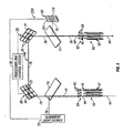
- FIG. 1 there is shown a diagrammatic representation of an exemplary closed-loop alignment system according to an embodiment of the invention, designated generally at 20, functioning with fiber optic cross-connect switch 23.
- the basic structure of known cross-connect switch 23 comprises respective first and second two-dimensional MEMS mirror arrays 26 and 29, each of which includes a plurality of respective individually tiltable mirrors 32 and 35 pivotally mounted on respective substrates 38 and 41.
- Mirrors 32 and 35 are used to direct a plurality of light beams, represented by signal beam 44 of light (only one signal beam 44 being shown for simplicity), emitted through ends 45 and 46 of a selected one of individual optical fibers 47 and 50 of respective first and second two-dimensional fiber optic arrays 53 and 56, to a desired optical fiber 50, 47 of the respective opposing fiber optic array 56, 53.
- the wavelength range typically used for optical telecommunications is about 1,250 to 1,650 nm, preferably at the infrared range of about 1500 nm.
- Respective first and second lenslet arrays 59 and 62 each comprising respective individual collimating lenslets 65 and 68 corresponding to a respective individual optical fiber 47 and 50, can be used to focus signal beams 44 out of fiber ends 45 and 46 into the respective optical fiber 47 and 50.
- the number of operational mirrors 32 and 35, first and second optical fibers 47 and 50, and lenslets 65 and 68, are equal.
- Lenslets 65 and 68 are optional in this system.
- Fixed mirror 71 is disposed opposite mirrors 32 and 35 between fiber optic arrays 53 and 56. While such cross-connect switches 23, as described thus far, are typically calibrated for temperature, there is no way to adjust them in operation, such as by providing feedback as to the accuracy of the positioning of mirror arrays 26 and 29 relative to optical fibers 47 and 50.
- Closed-loop alignment system 20 of an embodiment of the invention is employed to align the signal beams from the ends of fibers 47 and 50 to the ends of the fibers in the opposite array of optical fibers.
- the alignment system of the invention injects a visible wavelength alignment beam directly into the signal beams and detects visible wavelength combined fiber-ends images to determine the extent of alignment of the signals between the optical fiber arrays.
- This alignment system arrangement by being coincident with the signal beams, compensates for time and temperature drift which can occur in such cross-connect switches.
- the alignment system of Fig. 1 includes respective first and second selectively semi-transparent optical components or beam splitters 74 and 77 which are disposed, respectively, between first fiber optic array 53 and first mirror array 26, and between second fiber optic array 56 and second mirror array 29.
- the beam splitters are preferably dichroic mirrors but other functionally equivalent elements, such as diffraction gratings, could be used.
- Light source 75 emits a probe or alignment beam 76 having a wavelength differing from the signal wavelength by at least 50 nm.
- the wavelength of beam 76 can range from about 400 nm to about 900 nm, and for practical purposes is preferably about 800 nm. Because of the wavelength difference, this visible light beam does not interfere with signal beams 44 when they coincide.
- Light beam 76 intersects with or impinges on first dichroic mirror 74 and at least a portion of this alignment beam is reflected onto fiber ends 45.
- the images of the ends of fibers 47 form a plurality of light beams 78 which are reflected back to and partially through mirror 74.
- These alignment light beams are coincident with signal beams 44, which originate externally to fibers 47 and pass therethrough, and generally unimpeded through mirror 74.
- Dichroic mirror 77 at the output of the alignment system functions in a similar manner, as is explained below.
- Dichroic mirrors 74 and 77 are designed with a known layering scheme (not shown) wherein light at certain predetermined wavelengths (for example, signal beams 44) substantially pass therethrough without significant absorption or reflection. However, about fifty percent of light at other wavelengths, such as alignment beam 76, at an incident angle of, for example, about forty-five degrees, is reflected at a complementary forty-five degree angle (ninety-degree included angle) and the remaining fifty percent passes therethrough. Therefore, first dichroic mirror 74 acts to pass fifty percent of alignment beam 76 therethrough, which is lost, and fifty percent is reflected to optical fibers 47.
- predetermined wavelengths for example, signal beams 44
- alignment beam 76 at an incident angle of, for example, about forty-five degrees
- first dichroic mirror 74 acts to pass fifty percent of alignment beam 76 therethrough, which is lost, and fifty percent is reflected to optical fibers 47.
- An alignment beam 78 reflects off end 45 of an optical fiber 47 and retraces its path as an image thereof to first dichroic mirror 74, again with fifty percent lost (being reflected back toward light source 75), and fifty percent passing therethrough to mirror array 26.
- Alignment beam 78 is reflected from its respective tiltable mirror 32 at the desired angle as controlled by processing and control system 92, off fixed mirror 71, and off a tiltable mirror 35 of second mirror array 29, which is also controlled by processing and control system 92, to second dichroic mirror 77.
- Second dichroic mirror 77 acts to reflect fifty percent of alignment beam 78, which is lost, and pass fifty percent therethrough to optical fibers 50.
- An alignment beam 78 reflects off end 46 of an optical fiber 50 and retraces its path as a combined image of ends 45 and 46 of an optical fibers 47 and 50 to second dichroic mirror 77, with fifty percent passing therethrough, which is lost, and fifty percent being reflected therefrom as beam 79 onto detector array 83 as combined image 101.
- a signal beam 44 may travel both from fiber optic array 53 to 56, and from fiber optic array 56 to 53, simultaneously in both directions in all of the optical fibers since alignment system 20 positions the tiltable mirrors 32 and 35 of mirror arrays 26 and 29 the same, regardless of the direction of travel of signal beam 44.
- the purpose of the alignment is to have near complete overlap of the images of the ends 45, 46 of fibers 47, 50, thereby ensuring optimal coupling of optical signals between the fibers.
- detector array 83 may comprise an array of relatively inexpensive silicon detectors.
- a charge-coupled device (CCD) camera having a plurality of individual photosensitive detectors or sensors 119 such as in a 3000 x 3000 or a 5000 x 5000 array.
- An output signal (OS) of each individual photosensitive sensor 119 is input to processing and control system 92, which includes feedback controller 122 that compares the relative position, size, and shape of combined image 101, each being comprised of an image 123 of end 45 of one optical fiber 47, and an image 124 of end 46 of one optical fiber 50, to an acceptable relative position, size, and shape of a combined image (CI) stored in image memory 128.
- CCD charge-coupled device
- OS output signal
- processing and control system 92 which includes feedback controller 122 that compares the relative position, size, and shape of combined image 101, each being comprised of an image 123 of end 45 of one optical fiber 47, and an image 124 of end 46 of one optical fiber 50, to an acceptable relative position, size
- mirror position correction information is developed by feedback controller 122 and an appropriate feedback signal (FS) is sent to mirror driver 131 which integrates the feedback signal FS with newly arriving optical switching information (OSI) being communicated to mirror driver 131 from master switching controller 134.
- Appropriately corrected drive signals (CDS) are sent from mirror driver 131 to first or second mirror arrays 26 and 29, or both, to properly position respective individual tiltable mirrors 32 and 35 based on the feedback signal FS.
- FIG. 4 therein is shown a diagrammatic representation of closed loop alignment system 220 in accordance with the invention, functioning with second fiber optic cross-connect switch 146.
- Cross-connect switch 146 comprises mirror arrays 26 and 29, but note that there is no fixed mirror 71 disposed opposite the mirrors 32 and 35 between the fiber optic arrays 53 and 56.
- the respective mirror arrays 26 and 29 are tilted inwardly at about a forty-five degree angle to allow direct reflection of signal beams 44 emitted through respective optical fibers 47 and 50 directly from respective mirrors 32 and 35 to the other thereof, and to the desired optical fiber 47 and 50 of the respective opposing fiber optic array 53 and 56.
- the respective, optional, first and second lenslet arrays 59 and 62, having respective individual collimating lenslets 65 and 68, function in the same manner as in the earlier embodiments.
- Closed-loop alignment system 220 includes dichroic mirrors 74 and 77 which are disposed, respectively, between first fiber optic array 53 and first mirror array 26, and between second fiber optic array 56 and second mirror array 29.
- Light source 75 emits the visible wavelength alignment beam 76 which impinges on the first dichroic mirror as previously described with respect to the Fig. 1 embodiment. Except for intermediate fixed mirror 71, the Fig. 4 embodiment operates in the same manner as the Figs. 1-3 embodiment.
- Alignment beams 78 are employed to align respective signal beams 44 without wavelength interference.
- FIG. 5 therein is shown a diagrammatic representation of closed loop alignment system 320, functioning with third fiber optic cross-connect switch 149.
- cross-connect switch 149 comprises the mirror arrays 26 and 29 with the respective tiltable mirrors 32 and 35.
- Mirrors 32 and 35 are used to direct the signal beams 44 emitted through the optical fibers 47 and 50 of the respective fiber optic arrays 53 and 56 to the desired optical fiber 47 and 50 of the opposing fiber optic array 53 and 56.
- Lenslet arrays 59 and 62 function in the same manner as in the previously described embodiments.
- the Fig. 5 embodiment is a different arrangement of the same elements as in Fig. 4 , which elements function in the same manner as before.
- FIG. 6 therein is shown a diagrammatic representation of closed loop alignment system 420, functioning with fourth fiber optic cross-connect switch 152.
- Cross-connect switch 152 differs from the previously described embodiments in that it comprises mirror array 26 with tiltable mirrors 32 but does not include the second tiltable mirror array 29.
- Mirrors 32 are used to direct the signal beams 44 emitted through optical fibers 47 and 50 of fiber optic arrays 53 and 56 to the desired optical fiber 47 and 50 of the opposing fiber optic array 53 and 56.
- the respective, optional, first and second lenslet arrays 59 and 62, having respective individual collimating lenslets 65 and 68 function in the same manner as in the previously described embodiments. Note that this embodiment shows that the alignment system of this invention can function with an optical cross-connect switch having a single mirror array. It also reveals that the relative angles of the components are quite flexible, it only being necessary to direct signal beams from one fiber array to another.
- the alignment apparatus can be arranged to conform to any cross-connect switch configuration.
- This embodiment of closed loop alignment system 420 includes dichroic mirrors 74 and 77 which are disposed, respectively, between first fiber optic array 53 and mirror array 26, and between second fiber optic array 56 and mirror array 26.
- Light source 75 emits the alignment beam 76, as before, which impinges on first dichroic mirror 74.
- Light detector array 83 is affixed adjacent second dichroic mirror 77 to receive reflected light therefrom. As before, signal beams between optical fibers 47 and 50 are aligned when the optical images of ends 45 and 46 of the respective optical fibers are aligned, as detected by detectors 119 on array 83.
- FIG. 7 therein is shown a diagrammatic representation of closed loop alignment system 520, functioning with fifth fiber optic cross-connect switch 161.
- Cross-connect switch 161 comprises mirror array 26 and mirror array 164, comprising single mirror element 35 pivotally mounted on substrate 167.
- Mirrors 32 and 35 are used to direct signal beams 44, emitted through optical fibers 47 of fiber optic array 53, and optical fiber array 56, containing single second optical fiber 50, to a desired optical fiber 47 and 50 of the respective opposing fiber optic array 56 and single optical fiber 50.
- Respective, optional, lenslet arrays 59 and 62 function in the same manner as in the previously described embodiments.
- Closed loop alignment system 520 includes dichroic mirrors 74 and 77 which are disposed, respectively, between first fiber optic array 53 and first mirror array 26, and between second fiber optic array 56 (optical fiber 50) and second mirror array 164 (mirror 35).
- Light source 75 emits visual alignment beam 76 which impinges on first dichroic mirror 74.
- Light detector array 83 is affixed adjacent second dichroic mirror 77 to receive reflected light therefrom.
- the optical alignment system operates in the same manner as has been previously described with respect to other embodiments of the cross-connect switch. The primary difference is that one optical fiber array consists of a plurality of fibers and the other array is a single fiber.
- all signal beams from optical fiber array 53 are aligned with single fiber 50.
- One purpose for this optical switch is to mulitplex a selectable subset of different wavelength signals from different optical fibers 47 into single fiber 50.
- cross-connect switch can function as a demultiplexer where the optical signals enter through the single optical fiber and are dispersed as multiple signals through the array of multiple fibers. Appropriate changes as to the relative locations of the alignment beam source and the detector array can be made as needed.
- the alignment system of the invention is external to and can be adapted to any optical fiber cross-connect switch, and any practical combination of angles can be accommodated. It is even possible to employ the present alignment system with a cross-connect switch having the input and the output optical fibers bundled together in adjacent arrays. The ends of the fibers could all be oriented in the same direction or they could be oriented so that the coupling ends of the input and output fibers are 180° apart, with the fibers all in parallel.
- probe or alignment beam source 75 can be any of several different types. It could be an arc lamp, a laser diode, an LED, or an incandescent lamp, among others. Where there are unwanted wavelengths a filter can be employed at the output of the light source. Beam 76 is preferably collimated. It could be a coherent light beam, but that is not necessary.
- the wavelength of the probe beam should be matched with the most efficient detection wavelength of detector 83. Silicon sensors are preferred because they are effective and inexpensive, and a light beam at about 800 nm is easily detected by them. In reality it is envisioned that the probe beam can range in wavelength from the visible to the near-infrared.
- the beam splitters pass the signal beams with only nominal or insignificant losses in intensity.
- processing and control system 92 can be any suitable device such as a microcomputer or a PC, among others. It need only be able to accomplish the functions described and no specific device or element is necessary for this invention.
Landscapes
- Physics & Mathematics (AREA)
- General Physics & Mathematics (AREA)
- Optics & Photonics (AREA)
- Mechanical Light Control Or Optical Switches (AREA)
- Use Of Switch Circuits For Exchanges And Methods Of Control Of Multiplex Exchanges (AREA)
Claims (13)
- Commutateur (23, 146, 149, 152, 161) d'interconnexion optique permettant de coupler des signaux optiques d'un premier ensemble de longueurs d'onde à partir des extrémités (45) de fibres optiques (47) dans un premier réseau de fibres optiques (53) jusqu'aux extrémités (46) de fibres optiques (50) dans un deuxième réseau de fibres optiques (56), le commutateur d'interconnexion comportant au moins un premier réseau (26) de miroirs qui comprend au moins un miroir (32) pouvant être incliné et commandé individuellement, positionné de façon à diriger les faisceaux de signaux émis depuis l'extrémité d'une fibre optique dans un réseau de fibres optiques jusqu'à l'extrémité d'une autre fibre optique dans l'autre réseau de fibres optiques, et système d'alignement en boucle fermée comprenant :une source (75) d'un faisceau lumineux d'alignement comportant une deuxième longueur d'onde différente du premier ensemble de longueurs d'onde ;un réseau (83) de détecteurs comportant des signaux de sortie ;un moyen (74) d'injecter le faisceau d'alignement dans les faisceaux de signaux, le faisceau d'alignement étant réfléchi depuis les extrémités (45) des fibres optiques (47) dans le premier réseau (53) de fibres optiques et retraçant son trajet comme une image de celui-ci, et étant réfléchi depuis les extrémités (46) des fibres optiques (50) dans le deuxième réseau (56) de fibres optiques et retraçant son trajet comme une image combinée des extrémités (45, 46) des fibres optiques dans les premier et deuxième réseaux de fibres optiques ; etun moyen (77) de diriger l'image combinée réfléchie des extrémités des fibres optiques dans les premier et deuxième réseaux de fibres optiques sur ledit réseau de détecteurs, les signaux de sortie dudit réseau de détecteurs indiquant l'alignement relatif des images des extrémités des fibres à la fois des premier et deuxième réseaux de fibres optiques ;dans lequel ledit moyen d'injection comprend un composant optique sélectivement semi-transparent qui est transparent pour le premier ensemble de longueurs d'onde et semi-transparent pour la deuxième longueur d'onde.
- Commutateur d'interconnexion selon la revendication 1, et comprenant en outre un moyen (92) de traitement et de commande recevant les signaux de sortie dudit réseau de détecteurs, ledit moyen de traitement et de commande étant couplé aux commandes de miroir dans l'au moins un premier réseau de miroirs et fournissant des signaux pour déplacer les miroirs individuels parmi les miroirs inclinables dans ledit au moins un premier réseau de miroirs de façon à maintenir la coïncidence des images des extrémités des fibres optiques dans le premier réseau de fibres optiques.
- Commutateur d'interconnexion selon la revendication 1 ou 2, dans lequel ledit moyen de direction comprend un composant optique sélectivement semi-transparent qui est transparent pour le premier ensemble de longueurs d'onde et semi-transparent pour la deuxième longueur d'onde.
- Commutateur (23, 146, 149, 152, 161) d'interconnexion optique selon la revendication 1, dans lequel
le moyen d'injection est un premier composant optique (74) sélectivement semi-transparent configuré et positionné pour injecter le faisceau lumineux d'alignement dans les faisceaux de signaux ;
le moyen de diriger est un deuxième composant optique (77) sélectivement semi-transparent configuré et positionné pour réfléchir les images combinées des extrémités des fibres dans le premier réseau de fibres optiques superposé sur les extrémités des fibres dans le deuxième réseau de fibres optiques sur ledit réseau de détecteurs, les signaux de sortie dudit réseau de détecteurs indiquant le degré de coïncidence de chevauchement des images des extrémités des fibres à la fois des premier et deuxième réseau de fibres optiques ; et
dans lequel lesdits composants optiques sélectivement semi-transparents sont transparents pour le premier ensemble de longueurs d'onde et semi-transparents pour la deuxième longueur d'onde. - Commutateur d'interconnexion selon la revendication 4, et comprenant en outre un système (92) de traitement et de commande couplé aux commandes de miroir dans l'au moins un premier réseau de miroirs, ledit système de traitement et de commande fournissant des signaux pour déplacer individuellement les miroirs dans l'au moins un premier réseau de miroirs en réponse aux signaux de sortie provenant dudit réseau de détecteurs de façon à maintenir la coïncidence des images et ainsi l'alignement des signaux entre les fibres respectives dans les premier et deuxième réseaux de fibres optiques.
- Commutateur d'interconnexion optique selon la revendication 4 ou 5, dans lequel lesdits premier et deuxième composants optiques sélectivement semi-transparents sont sélectionnés parmi le groupe composé d'un miroir dichroïque et un réseau de diffraction.
- Commutateur d'interconnexion selon l'une des revendications 4 à 6, dans lequel ledit réseau de détecteurs comprend une pluralité d'éléments (119) de détection en silicium.
- Commutateur d'interconnexion selon l'une des revendications 4 à 7, dans lequel ledit réseau de détecteurs comprend un dispositif (83) à couplage de charge comportant une pluralité d'éléments (119) de détection, comportant chacun un signal de sortie couplé audit système de traitement et de commande, ledit système de traitement et de commande comprenant :une mémoire (128) d'images stockant des positions, tailles et formes relatives acceptables pour les images combinées ;un dispositif (122) de commande à rétroaction qui compare les positions, tailles et formes relatives des images combinées aux images combinées acceptables dans ladite mémoire d'images, ledit dispositif de commande à rétroaction comportant des signaux de commande de sortie ; etun dispositif (131) de commande de mise en miroir qui positionne individuellement les miroirs dans ledit au moins un premier réseau de miroirs conformément aux signaux de commande provenant dudit dispositif de commande à rétroaction.
- Commutateur d'interconnexion selon l'une des revendications 1 à 8, dans lequel ledit réseau de détecteurs comprend une caméra munie d'un dispositif à couplage de charge.
- Procédé d'alignement de faisceaux de signaux optiques entre les extrémités (45, 46) de fibres (47, 50) dans les premier et deuxième réseaux (53, 56) de fibres optiques dans un commutateur (23, 146, 149, 152, 161) d'interconnexion à fibre optique, les signaux optiques faisant partie d'un premier ensemble de longueurs d'onde, le commutateur comportant au moins un premier réseau (26) de miroirs comprenant au moins un miroir (32) pouvant être incliné et commandé individuellement, positionné de façon à diriger les faisceaux de signaux émis depuis l'extrémité d'une fibre optique dans un réseau de fibres optiques jusqu'à l'extrémité d'une autre fibre optique dans l'autre réseau de fibres optiques, le procédé consistant à :injecter dans les faisceaux de signaux un faisceau lumineux d'alignement comportant une deuxième longueur d'onde différente du premier ensemble de longueurs d'onde, dans lequel une source (75) de lumière visible et un premier élément optique (74) sélectivement semi-transparent sont employés pour injecter le faisceau d'alignement dans le commutateur d'interconnexion, dans lequel le premier élément optique sélectivement semi-transparent est transparent pour le premier ensemble de longueurs d'onde et est semi-transparent pour la deuxième longueur d'onde ;créer des images combinées avec le faisceau lumineux d'alignement des extrémités des fibres optiques dans les premier et deuxième réseaux de fibres optiques en réfléchissant le faisceau d'alignement depuis les extrémités (45) de fibres optiques (47) dans le premier réseau (53) de fibres optiques avec le faisceau d'alignement retraçant son trajet comme une image de celui-ci, et en réfléchissant le faisceau d'alignement depuis les extrémités (46) des fibres optiques (50) dans le deuxième réseau (56) de fibres optiques avec le faisceau d'alignement retraçant son trajet comme une image combinée des extrémités (45, 46) des fibres optiques dans les premier et deuxième réseaux de fibres optiques ;réfléchir les images combinées des extrémités des fibres dans les premier et deuxième réseaux de fibres optiques sur un réseau (83) de détecteurs ; etfournir des signaux de sortie depuis le réseau de détecteurs, lesquels signaux de sortie indiquent le degré de coïncidence de chevauchement des images des extrémités des fibres à la fois des premier et deuxième réseaux de fibres optiques.
- Procédé selon la revendication 10, et consistant en outre à comparer les signaux de sortie provenant du réseau de détecteurs aux signaux stockés correspondant à des positions, tailles et formes relatives acceptables pour les images combinées.
- Procédé selon la revendication 11, et consistant en outre à ajuster les miroirs pouvant être inclinés et commandés dans le premier réseau de miroirs pour une coïncidence substantielle des positions, tailles et formes des images des extrémités des fibres optiques du premier réseau de fibres optiques avec les images des extrémités des fibres optiques dans le deuxième réseau de fibres optiques.
- Procédé selon l'une des revendications 10 à 12, dans lequel un deuxième élément optique (77) sélectivement semi-transparent est employé pour réfléchir les images combinées des extrémités des fibres à la fois des premier et deuxième réseaux de fibres optiques sur le réseau de détecteurs, dans lequel le deuxième élément optique sélectivement semi-transparent est transparent pour le premier ensemble de longueurs d'onde et est semi-transparent pour la deuxième longueur d'onde.
Applications Claiming Priority (2)
| Application Number | Priority Date | Filing Date | Title |
|---|---|---|---|
| US409271 | 2003-04-07 | ||
| US10/409,271 US6934438B2 (en) | 2003-04-07 | 2003-04-07 | Closed loop alignment system for fiber optic cross-connect switches |
Publications (3)
| Publication Number | Publication Date |
|---|---|
| EP1467231A2 EP1467231A2 (fr) | 2004-10-13 |
| EP1467231A3 EP1467231A3 (fr) | 2004-12-29 |
| EP1467231B1 true EP1467231B1 (fr) | 2010-04-14 |
Family
ID=32869191
Family Applications (1)
| Application Number | Title | Priority Date | Filing Date |
|---|---|---|---|
| EP03026122A Expired - Lifetime EP1467231B1 (fr) | 2003-04-07 | 2003-11-13 | Système d'alignement à boucle fermé pour répartiteur/commutateur à fibres optiques |
Country Status (4)
| Country | Link |
|---|---|
| US (1) | US6934438B2 (fr) |
| EP (1) | EP1467231B1 (fr) |
| JP (1) | JP2004310104A (fr) |
| DE (1) | DE60332089D1 (fr) |
Families Citing this family (35)
| Publication number | Priority date | Publication date | Assignee | Title |
|---|---|---|---|---|
| US7177497B2 (en) * | 2003-10-02 | 2007-02-13 | Trex Enterprises Corp. | Porous silicon filter for wavelength multiplexing or de-multiplexing |
| US7734127B2 (en) * | 2007-03-26 | 2010-06-08 | Trex Enterprises Corp. | Optical switch module |
| JP4493538B2 (ja) * | 2005-03-31 | 2010-06-30 | 富士通株式会社 | 波長選択スイッチ |
| WO2006110723A2 (fr) * | 2005-04-11 | 2006-10-19 | Infotonics Technology Center, Inc. | Systemes et procedes pour le controle sanguin |
| WO2007008800A2 (fr) * | 2005-07-11 | 2007-01-18 | Infotonics Technology Center, Inc. | Cartouche remplacable destinee a systeme de test d'allergie |
| US20070276211A1 (en) * | 2006-05-26 | 2007-11-29 | Jose Mir | Compact minimally invasive biomedical monitor |
| US20100100005A1 (en) * | 2006-07-11 | 2010-04-22 | Infotonics Technology Center, Inc. | Minimally invasive allergy testing system with coated allergens |
| US7356216B1 (en) * | 2006-12-20 | 2008-04-08 | The Boeing Company | Optical cross-connect |
| US7548682B2 (en) * | 2007-03-26 | 2009-06-16 | Trex Enterprises Corp. | Optical fiber array alignment unit |
| US7805080B2 (en) * | 2007-06-22 | 2010-09-28 | Hewlett-Packard Development Company, L.P. | Optical interconnect |
| US8328720B2 (en) * | 2007-08-10 | 2012-12-11 | Infotonics Technology Center, Inc. | MEMS interstitial prothrombin time test |
| US7664348B2 (en) * | 2007-12-21 | 2010-02-16 | Teledyne Scientific & Imaging, Llc | Optical switch with reconfigurable broadcasting and combining capabilities |
| JP2011069923A (ja) * | 2009-09-24 | 2011-04-07 | Fujitsu Ltd | 光学装置の光軸調整システム及び光学装置の光軸調整方法 |
| CN102135645B (zh) * | 2011-02-21 | 2013-11-06 | 华为技术有限公司 | 光开关系统和信号光的反馈控制方法 |
| US10244981B2 (en) * | 2011-03-30 | 2019-04-02 | SensiVida Medical Technologies, Inc. | Skin test image analysis apparatuses and methods thereof |
| US9794016B2 (en) * | 2011-10-05 | 2017-10-17 | University Of Central Florida Research Foundation, Inc. | Systems and methods for processing space-multiplexed optical signals |
| US9335486B2 (en) | 2012-01-20 | 2016-05-10 | Afl Telecommunications Llc | Method and apparatus for aligning a large diameter optical fiber |
| US9143232B2 (en) | 2012-03-29 | 2015-09-22 | Intel Corporation | Trackable wireless optical communication |
| CN104583824B (zh) * | 2012-07-19 | 2018-05-18 | 菲尼萨公司 | 极化不同波长选择开关 |
| CN104181690B (zh) * | 2013-05-28 | 2017-05-10 | 华为技术有限公司 | 一种3d‑mems光开关 |
| CN104635334B (zh) * | 2013-11-15 | 2017-09-12 | 华为技术有限公司 | 一种3d‑mems光开关 |
| US9130906B1 (en) | 2014-05-23 | 2015-09-08 | The United States Of America As Represented By The Secretary Of The Navy | Method and apparatus for automated secure one-way data transmission |
| US10464488B2 (en) | 2016-09-22 | 2019-11-05 | Gentex Corporation | Mirror flipper assembly |
| CN109890660B (zh) | 2016-10-31 | 2022-04-26 | 金泰克斯公司 | 用于镜总成的凸轮驱动的拨动开关 |
| CN110662672B (zh) | 2017-06-12 | 2023-03-24 | 金泰克斯公司 | 自动倾斜离合器机构 |
| US10317626B2 (en) | 2017-06-15 | 2019-06-11 | Google Llc | Inner and outer collimator elements for an optical circuit switch |
| US10596968B2 (en) | 2017-09-20 | 2020-03-24 | Gentex Corporation | Prism toggle spring |
| TWI781243B (zh) * | 2018-10-31 | 2022-10-21 | 國立清華大學 | 級聯鏡列及包含其之掃描系統 |
| US11119195B2 (en) | 2018-12-07 | 2021-09-14 | Beijing Voyager Technology Co., Ltd. | Mirror assembly for light steering |
| US11181621B2 (en) | 2018-12-07 | 2021-11-23 | Beijing Voyager Technology Co., Ltd. | Mirror assembly for light steering |
| WO2020117287A1 (fr) | 2018-12-07 | 2020-06-11 | Didi Research America, Llc | Ensemble miroir pour direction de lumière |
| US10422881B1 (en) | 2018-12-07 | 2019-09-24 | Didi Research America, Llc | Mirror assembly for light steering |
| WO2021247754A1 (fr) * | 2020-06-03 | 2021-12-09 | Intuitive Surgical Operations, Inc. | Guidage de la lumière dans une fibre optique |
| US11561348B2 (en) * | 2020-11-12 | 2023-01-24 | Alpine Optoelectronics, Inc. | Optical alignment systems and methods |
| CN115421311B (zh) * | 2022-11-04 | 2023-01-13 | 中国航天三江集团有限公司 | 高精度光束合成光路辅助对准装置 |
Family Cites Families (9)
| Publication number | Priority date | Publication date | Assignee | Title |
|---|---|---|---|---|
| US6483962B1 (en) | 2000-05-24 | 2002-11-19 | Vlad J. Novotny | Optical cross connect switching array system with optical feedback |
| US6668108B1 (en) | 2000-06-02 | 2003-12-23 | Calient Networks, Inc. | Optical cross-connect switch with integrated optical signal tap |
| US6300665B1 (en) | 2000-09-28 | 2001-10-09 | Xerox Corporation | Structure for an optical switch on a silicon on insulator substrate |
| US6567574B1 (en) * | 2000-10-06 | 2003-05-20 | Omm, Inc. | Modular three-dimensional optical switch |
| US6760505B1 (en) * | 2000-11-08 | 2004-07-06 | Xerox Corporation | Method of aligning mirrors in an optical cross switch |
| US6600849B2 (en) | 2000-11-20 | 2003-07-29 | Jds Uniphase Inc. | Control system for optical cross-connect switches |
| US6591029B1 (en) * | 2001-01-05 | 2003-07-08 | Tellium, Inc | Optical switch and method for aligning optical switch components |
| US6539142B2 (en) | 2001-06-01 | 2003-03-25 | Agilent Technologies, Inc. | System and method for actively aligning mirrors in an optical switch |
| US6947629B2 (en) * | 2002-09-24 | 2005-09-20 | Transoptix, Inc. | 3D image feedback optical beam alignment |
-
2003
- 2003-04-07 US US10/409,271 patent/US6934438B2/en not_active Expired - Fee Related
- 2003-11-13 EP EP03026122A patent/EP1467231B1/fr not_active Expired - Lifetime
- 2003-11-13 DE DE60332089T patent/DE60332089D1/de not_active Expired - Lifetime
-
2004
- 2004-04-05 JP JP2004111284A patent/JP2004310104A/ja not_active Withdrawn
Also Published As
| Publication number | Publication date |
|---|---|
| US20040202407A1 (en) | 2004-10-14 |
| EP1467231A2 (fr) | 2004-10-13 |
| JP2004310104A (ja) | 2004-11-04 |
| DE60332089D1 (de) | 2010-05-27 |
| US6934438B2 (en) | 2005-08-23 |
| EP1467231A3 (fr) | 2004-12-29 |
Similar Documents
| Publication | Publication Date | Title |
|---|---|---|
| US6934438B2 (en) | Closed loop alignment system for fiber optic cross-connect switches | |
| US6798992B1 (en) | Method and device for optically crossconnecting optical signals using tilting mirror MEMS with drift monitoring feature | |
| JP5079088B2 (ja) | 光インターコネクト | |
| US6549692B1 (en) | Optical monitoring of the angular position of micro mirrors in an optical switch | |
| EP2564147B1 (fr) | Test incorporé (bit) d'émetteur/récepteur optique | |
| US6787745B2 (en) | Fiber optic signal detector with two switchable input channels | |
| US6654517B2 (en) | Optical devices engaged to fibers with angle-polished facets | |
| EP1271202B1 (fr) | Commutateur optique MEMS avec système d'imagerie | |
| EP0768542B2 (fr) | Appareil optique pour détermination de distance | |
| US6580846B1 (en) | Actively-controllable optical switches based on optical position sensing and applications in optical switching arrays | |
| US6600849B2 (en) | Control system for optical cross-connect switches | |
| CA2463919C (fr) | Architecture de syteme de matrice de commutation optique | |
| EP1357408B1 (fr) | Matrice de commutation optique comportant un reseau de micro-miroirs et procédé associé | |
| JP4033550B2 (ja) | 光学装置、光電スイッチ、ファイバ型光電スイッチおよび色識別センサ | |
| US20080056723A1 (en) | Multiple access free space laser communication method and apparatus | |
| US6906838B2 (en) | Systems and methods for routing optical beams along optical paths using steerable mirrors | |
| EP0658987A1 (fr) | Dispositif pour communication optique dans l'espace | |
| WO2001096924A1 (fr) | Commutateurs optiques activement reglables reposant sur la detection de position optique et applications relatives aux matrices de commutation optique | |
| JP3192359B2 (ja) | 空間光通信装置 | |
| JPS5926006A (ja) | マルチビ−ム走査装置におけるビ−ム位置検知方法 | |
| US7236709B1 (en) | Multi-input wavelocker for controlling laser wavelengths of multiple lasers | |
| CA2363609A1 (fr) | Systeme de commande de commutateurs d'interconnexion optiques | |
| US8150267B1 (en) | Optical interconnect | |
| JP4127113B2 (ja) | 光ファイバへの入射光モニタ装置及びこれを備えた光伝送装置 | |
| WO2003077592A1 (fr) | Systeme de configuration pour dispositifs de commutation optique |
Legal Events
| Date | Code | Title | Description |
|---|---|---|---|
| PUAI | Public reference made under article 153(3) epc to a published international application that has entered the european phase |
Free format text: ORIGINAL CODE: 0009012 |
|
| AK | Designated contracting states |
Kind code of ref document: A2 Designated state(s): AT BE BG CH CY CZ DE DK EE ES FI FR GB GR HU IE IT LI LU MC NL PT RO SE SI SK TR |
|
| AX | Request for extension of the european patent |
Extension state: AL LT LV MK |
|
| PUAL | Search report despatched |
Free format text: ORIGINAL CODE: 0009013 |
|
| AK | Designated contracting states |
Kind code of ref document: A3 Designated state(s): AT BE BG CH CY CZ DE DK EE ES FI FR GB GR HU IE IT LI LU MC NL PT RO SE SI SK TR |
|
| AX | Request for extension of the european patent |
Extension state: AL LT LV MK |
|
| 17P | Request for examination filed |
Effective date: 20050503 |
|
| AKX | Designation fees paid |
Designated state(s): DE FR GB |
|
| RAP1 | Party data changed (applicant data changed or rights of an application transferred) |
Owner name: AVAGO TECHNOLOGIES FIBER IP (SINGAPORE) PTE. LTD. |
|
| GRAP | Despatch of communication of intention to grant a patent |
Free format text: ORIGINAL CODE: EPIDOSNIGR1 |
|
| GRAS | Grant fee paid |
Free format text: ORIGINAL CODE: EPIDOSNIGR3 |
|
| GRAA | (expected) grant |
Free format text: ORIGINAL CODE: 0009210 |
|
| AK | Designated contracting states |
Kind code of ref document: B1 Designated state(s): DE FR GB |
|
| REG | Reference to a national code |
Ref country code: GB Ref legal event code: FG4D |
|
| REF | Corresponds to: |
Ref document number: 60332089 Country of ref document: DE Date of ref document: 20100527 Kind code of ref document: P |
|
| PLBE | No opposition filed within time limit |
Free format text: ORIGINAL CODE: 0009261 |
|
| STAA | Information on the status of an ep patent application or granted ep patent |
Free format text: STATUS: NO OPPOSITION FILED WITHIN TIME LIMIT |
|
| 26N | No opposition filed |
Effective date: 20110117 |
|
| GBPC | Gb: european patent ceased through non-payment of renewal fee |
Effective date: 20101113 |
|
| REG | Reference to a national code |
Ref country code: FR Ref legal event code: ST Effective date: 20110801 |
|
| PG25 | Lapsed in a contracting state [announced via postgrant information from national office to epo] |
Ref country code: FR Free format text: LAPSE BECAUSE OF NON-PAYMENT OF DUE FEES Effective date: 20101130 |
|
| PG25 | Lapsed in a contracting state [announced via postgrant information from national office to epo] |
Ref country code: GB Free format text: LAPSE BECAUSE OF NON-PAYMENT OF DUE FEES Effective date: 20101113 |
|
| PGFP | Annual fee paid to national office [announced via postgrant information from national office to epo] |
Ref country code: DE Payment date: 20121107 Year of fee payment: 10 |
|
| REG | Reference to a national code |
Ref country code: DE Ref legal event code: R082 Ref document number: 60332089 Country of ref document: DE Representative=s name: DILG HAEUSLER SCHINDELMANN PATENTANWALTSGESELL, DE |
|
| REG | Reference to a national code |
Ref country code: DE Ref legal event code: R082 Ref document number: 60332089 Country of ref document: DE Representative=s name: DILG HAEUSLER SCHINDELMANN PATENTANWALTSGESELL, DE Effective date: 20130702 Ref country code: DE Ref legal event code: R081 Ref document number: 60332089 Country of ref document: DE Owner name: AVAGO TECHNOLOGIES GENERAL IP (SINGAPORE) PTE., SG Free format text: FORMER OWNER: AVAGO TECHNOLOGIES FIBER IP (SINGAPORE) PTE. LTD., SINGAPORE, SG Effective date: 20130702 |
|
| PG25 | Lapsed in a contracting state [announced via postgrant information from national office to epo] |
Ref country code: DE Free format text: LAPSE BECAUSE OF NON-PAYMENT OF DUE FEES Effective date: 20140603 |
|
| REG | Reference to a national code |
Ref country code: DE Ref legal event code: R119 Ref document number: 60332089 Country of ref document: DE Effective date: 20140603 |