EP1467470A2 - Rotor de machine tournante électrique et procédé pour sa fabrication - Google Patents
Rotor de machine tournante électrique et procédé pour sa fabrication Download PDFInfo
- Publication number
- EP1467470A2 EP1467470A2 EP04008254A EP04008254A EP1467470A2 EP 1467470 A2 EP1467470 A2 EP 1467470A2 EP 04008254 A EP04008254 A EP 04008254A EP 04008254 A EP04008254 A EP 04008254A EP 1467470 A2 EP1467470 A2 EP 1467470A2
- Authority
- EP
- European Patent Office
- Prior art keywords
- projections
- sheet
- rotor
- material sheet
- teeth
- Prior art date
- Legal status (The legal status is an assumption and is not a legal conclusion. Google has not performed a legal analysis and makes no representation as to the accuracy of the status listed.)
- Granted
Links
Images



Classifications
-
- H—ELECTRICITY
- H02—GENERATION; CONVERSION OR DISTRIBUTION OF ELECTRIC POWER
- H02K—DYNAMO-ELECTRIC MACHINES
- H02K15/00—Processes or apparatus specially adapted for manufacturing, assembling, maintaining or repairing of dynamo-electric machines
- H02K15/02—Processes or apparatus specially adapted for manufacturing, assembling, maintaining or repairing of dynamo-electric machines of stator or rotor bodies
- H02K15/021—Magnetic cores
- H02K15/026—Wound cores
-
- H—ELECTRICITY
- H02—GENERATION; CONVERSION OR DISTRIBUTION OF ELECTRIC POWER
- H02K—DYNAMO-ELECTRIC MACHINES
- H02K1/00—Details of the magnetic circuit
- H02K1/06—Details of the magnetic circuit characterised by the shape, form or construction
- H02K1/22—Rotating parts of the magnetic circuit
- H02K1/26—Rotor cores with slots for windings
-
- H—ELECTRICITY
- H02—GENERATION; CONVERSION OR DISTRIBUTION OF ELECTRIC POWER
- H02K—DYNAMO-ELECTRIC MACHINES
- H02K23/00—DC commutator motors or generators having mechanical commutator; Universal AC/DC commutator motors
- H02K23/02—DC commutator motors or generators having mechanical commutator; Universal AC/DC commutator motors characterised by arrangement for exciting
- H02K23/04—DC commutator motors or generators having mechanical commutator; Universal AC/DC commutator motors characterised by arrangement for exciting having permanent magnet excitation
-
- H—ELECTRICITY
- H02—GENERATION; CONVERSION OR DISTRIBUTION OF ELECTRIC POWER
- H02K—DYNAMO-ELECTRIC MACHINES
- H02K13/00—Structural associations of current collectors with motors or generators, e.g. brush mounting plates or connections to windings; Disposition of current collectors in motors or generators; Arrangements for improving commutation
- H02K13/006—Structural associations of commutators
-
- Y—GENERAL TAGGING OF NEW TECHNOLOGICAL DEVELOPMENTS; GENERAL TAGGING OF CROSS-SECTIONAL TECHNOLOGIES SPANNING OVER SEVERAL SECTIONS OF THE IPC; TECHNICAL SUBJECTS COVERED BY FORMER USPC CROSS-REFERENCE ART COLLECTIONS [XRACs] AND DIGESTS
- Y10—TECHNICAL SUBJECTS COVERED BY FORMER USPC
- Y10T—TECHNICAL SUBJECTS COVERED BY FORMER US CLASSIFICATION
- Y10T29/00—Metal working
- Y10T29/49—Method of mechanical manufacture
- Y10T29/49002—Electrical device making
- Y10T29/49009—Dynamoelectric machine
-
- Y—GENERAL TAGGING OF NEW TECHNOLOGICAL DEVELOPMENTS; GENERAL TAGGING OF CROSS-SECTIONAL TECHNOLOGIES SPANNING OVER SEVERAL SECTIONS OF THE IPC; TECHNICAL SUBJECTS COVERED BY FORMER USPC CROSS-REFERENCE ART COLLECTIONS [XRACs] AND DIGESTS
- Y10—TECHNICAL SUBJECTS COVERED BY FORMER USPC
- Y10T—TECHNICAL SUBJECTS COVERED BY FORMER US CLASSIFICATION
- Y10T29/00—Metal working
- Y10T29/49—Method of mechanical manufacture
- Y10T29/49002—Electrical device making
- Y10T29/49009—Dynamoelectric machine
- Y10T29/49012—Rotor
-
- Y—GENERAL TAGGING OF NEW TECHNOLOGICAL DEVELOPMENTS; GENERAL TAGGING OF CROSS-SECTIONAL TECHNOLOGIES SPANNING OVER SEVERAL SECTIONS OF THE IPC; TECHNICAL SUBJECTS COVERED BY FORMER USPC CROSS-REFERENCE ART COLLECTIONS [XRACs] AND DIGESTS
- Y10—TECHNICAL SUBJECTS COVERED BY FORMER USPC
- Y10T—TECHNICAL SUBJECTS COVERED BY FORMER US CLASSIFICATION
- Y10T29/00—Metal working
- Y10T29/49—Method of mechanical manufacture
- Y10T29/49002—Electrical device making
- Y10T29/4902—Electromagnet, transformer or inductor
- Y10T29/49071—Electromagnet, transformer or inductor by winding or coiling
Definitions
- the present invention relates to a rotor of a rotary electric machine, particularly a rotor of a commutator-type rotary electric machine, and a method of manufacturing the rotor.
- a d.c. commutating motor is used for the starter motor.
- a yield rate of a rotor core is very low in the starter motor.
- the rotor core is formed by a stack of thin steel sheets. The sheet is produced by stamping a square-shaped steel sheet with a predetermined dimension. When the round-shaped rotor is formed of the square-shaped steel sheet, the yield rate is ⁇ /4. In fact, approximately 40% to 50% of the material is discarded.
- Japanese Patent Publication No. JP-B2-61-11065 proposes a manufacturing method of a rotor of a rotary electric machine for improving the yield rate of the sheet.
- a stator of the rotary electric machine that has a ring-shaped cross-section, especially, a stator core of a revolving-field type electric machine, is produced by helically winding a sheet in a form of belt.
- this method is applied to make the rotor core of a rotary electric machine.
- the belt sheet for the rotor core is in a form of comb and has long teeth.
- the belt sheet is produced from a base metal sheet. In the base metal sheet, two belt sheets are opposed and arranged such that the teeth of a first sheet are intermeshed with the teeth of a second sheet.
- the rotor core is produced by helically winding one of the first and second sheets.
- notches are formed.
- the belt sheets are arranged in the base metal sheet such that the teeth are opposed to each other. That is, the notches of the first sheet do not mate with the notches of the second sheet. As a result, the material around the notches is discarded. Therefore, it is difficult to fully reduce scraps of the material. Also, in a belt sheet used for making a core in which side walls of the teeth defining slots are parallel or a core having a large number of slots such as a rotor core of a starter, especially, a magnet type, it is difficult to arrange two belt sheets in the base metal sheet such that the teeth of the first sheet are intermeshed with the teeth of the second sheet.
- Fig. 10 shows an example of a base metal sheet for a rotor core of a starter.
- the base sheet two sheets are arranged such that the teeth are opposed to each other.
- Each sheet is helically wound as shown in Fig. 11.
- the teeth of the first sheet are not intermeshed with the teeth of the second sheet. Therefore, it is difficult to improve a yield rate in this method. Accordingly, the sheets shown in Fig. 10 are not widely used.
- the sheet used in JP-B2-61-11065 since the projections formed on the side opposite to the teeth are short, it is difficult to helically wind this sheet.
- the present invention is made in view of the foregoing matters, and it is an object of the present invention to provide a rotor of a rotary electric machine in which a rotor core is constructed of a helically wound sheet, which is easily wound and produced with an enhanced yield rate.
- a rotor core is constructed of a helically wound sheet.
- the sheet is substantially in a form of belt.
- the sheet forms teeth extending from a first side of its middle connecting portion in a direction substantially perpendicular to a longitudinal direction of the sheet and projections projecting from a second side of the middle connecting portion in the direction opposite to the teeth.
- the projections are spaced and defines recesses between them.
- Each of the teeth has a substantially trapezoidal shape or a substantially rectangular shape.
- Each of the projections and each of the recesses have substantially the same dimension with respect to a centerline equidistant between a first line passing through the tops of the projections and a second line passing through the bottoms of the recesses. That is, the dimension of the tooth top is equal to the dimension of the tooth base.
- the sheet is helically wound in a condition that the projections and recesses are located in a radially inside. Accordingly, a yield rate of the sheet is improved and the sheet is easily wound with a less force.
- a rotor core of a rotor of a rotary electric machine of the embodiment is produced by helically winding a material sheet.
- the material sheet is one of a pair of material sheets 1, 2 included in a base sheet 10 shown in Fig. 1.
- each of the material sheets 1, 2 has teeth 11, an intermediate connecting portion 15, and fixing projection and recess portions 20.
- the teeth 11 extend from a first side of the connecting portion 15.
- Each of the teeth 11 has a substantially trapezoidal shape or a substantially rectangular shape.
- the tooth 11 has nails 12 at its end for restricting conductors from coming out from the rotor core.
- the nails 12 are formed into a substantially V-shape with respect to a longitudinal line of the tooth 11 that is coincident with a radial line of the rotor core when the material sheet 1, 2 is wound.
- the teeth 11 and the connecting portion 15 define magnetic paths in a rotor core.
- the projections and recess portions 20 includes a plurality of projections 21.
- the projections 21 extend in a direction opposite to the teeth 11 from a second side of the connecting portion 15.
- the projections 21 are spaced in a longitudinal direction of the material sheet 1, 2, so that recesses 22 are formed between the adjacent projections 21.
- two material sheets 1, 2 are combined in a condition that the projection and recess portions 20 are intermeshed.
- the projections 21 and the recesses 22 are formed to have the same shapes or dimensions with respect to a centerline A-A. That is, the dimension of a tooth top is substantially the same as the dimension of a tooth base with respect to the centerline A-A.
- the centerline A-A is equidistant between a first line passing through the tops of the projections 21 and a second line passing through the bottoms of the recesses 22.
- the intermeshed portions can be formed to completely mate with each other by a method such as pressing.
- small gaps can be allowed between the intermeshed portions of the two sheets 1, 2. It is less likely to affect to the present invention. Also, it is not always necessary that the number of teeth 11 is the same as the number of the projections 21 or the recesses 22 in the material sheet 1, 2.
- the material sheet 1, 2 is helically wound and therefore, the rotor core 30 is produced.
- the material sheet 1, 2 is wound such that the projections 21 and the recesses 22 are located in a radially inside.
- gaps 23 are formed between the projections 21 that are arranged adjacent in a circumferential direction of the rotor core 30.
- the material sheets 1, 2 are formed in a single base sheet 10 by stamping such as by pressing. Two material sheets 1, 2 produced from the single base sheet 10 are separated and helically wound. Thus, two separate cores 30 are produced.
- the material sheet 1, 2 is wound such that the projections 21 are located radially inside and the teeth 11 are located radially outside of the core 30.
- the teeth 11 forms slots between them on the outer periphery of the core 30.
- each projection 21 forms an arc portion 24 at its top, which is illustrated in a circle B in Fig. 1.
- the arc portion 24 has a curvature corresponding to a curvature of an outer circumferential surface of a rotor shaft, which is fixed in the radially inside of the rotor core 30.
- the arc portions 24 provide a sufficient holding force for holding the rotor shaft inside the rotor core 30.
- the teeth 11, the projections 21 and the connecting portion 15 have a following dimensional relation. As shown in Fig. 1, a tooth height H and a total dimension T of the projection 21 and the connecting portion 15 with respect to a direction perpendicular to the longitudinal direction of the material sheet 1, 2 satisfy a relation 2 x H ⁇ T.
- the rotor core 30 and the rotor shaft 31 constitute a rotor 100 of a rotary electric machine.
- a plurality of upper conductors 41 and lower conductors 42 are fixed in the slots formed between the teeth 11 on the radially outside of the rotor core 30.
- the upper conductors 41 and the lower conductors 42 generally extend in the slots in an axial direction of the rotor 100 and substantially perpendicularly bend at the axial ends of the rotor core 30.
- the ends of the upper conductors 41 and the lower conductor 42 form outer conductor portions 41a and inner conductor portions 42a extending in the radial direction of the rotor core 30 along axial end surfaces of the core 30.
- outer conductor portions 41a and the lower conductor portions 42a are electrically and mechanically connected at the respective ends 51 located radially inside of the rotor core 30.
- a first insulating plate 43 is provided between the outer conductor portions 41a and the inner conductor portions 42a.
- a second insulating plate 44 is provided between the inner conductor portions 42a and the axial end surface of the core 30.
- the upper conductor 41 and the outer conductor portions 41a form a substantially U-shaped conductor
- the lower conductor portion 42 and the inner conductor portions 42a form a substantially U-shaped conductor.
- the U-shaped conductors are mounted on the core 30 such that the rotor core 30 is sandwiched by the outer and inner conductor portions 41a, 42a in the axial direction.
- the nails 12 formed at the ends of the teeth 11 are bend in the radially inward direction to restrict the conductors 41, 42 from coming out from the slots or expanding in the radially outward direction, as shown in Fig. 3B.
- the nails 12 have dimensions such that a distance S between the nail 12 of a first tooth 11 and the nail 12 of an adjacent second tooth 11 is smaller than a circumferential width W of the conductor 41, 42 mounted between the first tooth 11 and the second tooth 11, in a condition where the nails 12 are bend.
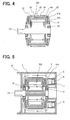
- the rotor 100 shown in Fig. 4 is employed to a permanent-magnet rotary electric machine shown in Fig. 5.
- a permanent-magnet rotary electric machine shown in Fig. 5.
- the rotor shaft 31 is held between a front end 3a of the yoke 3 and an end plate 9 through bearings 61.
- Brushes 6 are slidably held in brush holders 5 fixed to the inside surface of the end plate 9.
- the brushes 6 are biased toward the axial end face of the outer conductor portions 41a of the rotor 100 by springs 7 housed inside the brush holders 6.
- the yoke 3 connects to a fixing housing 8, which is partly illustrated in Fig. 5.
- Fig. 6 shows the base sheet 10 of the second embodiment.
- the shapes of the projections 21 and the recesses 22 of the fixing projection and recess portions 20 are different from those of the first embodiment shown in Fig. 1.
- the shapes or areas of the projections 21 and the recesses 22 are different with respect to the centerline A-A between a first line passing through the tops of the projections 21 and a second line passing through the bottoms of the recesses 22.
- the shapes of the intermeshed portions 20 are different between the two material sheets 1, 2.
- two material sheets 1, 2 having different shapes are produced from the single base sheet 10 at the same time.
- each material sheet 1, 2 has engaging means such as stamped projections 20a.
- the engaging means are used for engaging or associating sheet segments after the material sheet 1, 2 is helically wound.
- the stamped projection 20a is embossed by half-shearing the material sheet 1, 2 in a direction that a thickness of the sheet is measured, as shown in Fig. 8.
- the projections 20a are formed within the projections 21, not in the connecting portion 15.
- the stamped projections 20a overlap and engage one another between the sheet segments, which are layered in the axial direction and engage, as shown in Fig. 9.
- the material sheets 1, 2 are arranged in the base sheet 10 such that the fixing projection and recess portions 20 are opposed and intermeshed with each other. Therefore, a yield rate is increased higher than a base sheet in which the material sheets are arranged such that teeth thereof are opposed. In the base sheet in which the teeth are opposed between the material sheets, a yield rate is 60%. On the other hand, in the base sheet 10 of the first and second embodiments, the yield rate is increased to 80%. Further, when the projections 21 of the two material sheets 1, 2 are formed to completely mate, a yield at the intermeshed portions is 100%. By this, the yield rate is further improved.
- the projection and recess portions 20 can have different shapes in two material sheets 1, 2, as in the second embodiment.
- two rotors having different specifications or characteristics can be produced at the same time with a high yield rate. Accordingly, the production efficiency is improved in producing multiple types or models of rotors.
- the shape of core is different according to a winding specification of the rotary electric machine.
- a rotor in which a pair of upper and lower conductors is mounted in the slot so called in a single turn-type rotor, the teeth are low.
- a rotor core for such rotor is produced by helically winding the material sheet, since the dimension of the connecting portion is relatively large, it is difficult to helically wind such material sheet. To solve this problem, it is required to increase a diameter of the rotor shaft.
- the teeth 11, the projections 21 and the connecting portion 15 are formed such that the height H of the teeth 11 is equal to or less than the half dimension T of the projection 21 and the connecting portion 15 (2 x H ⁇ T). Accordingly, the material sheet 1, 2 can be easily wound without requiring the increase in the diameter of the rotor shaft 31.
- the material sheets 1, 2 are formed such that the teeth 11 are located at the sides of the base sheet 10. That is, the teeth 11 extend to the outside of the base sheet 10. If the nails 12 are formed to extend straight from the teeth 11, the yield rate at the sides of the base sheet 10 is reduced.
- the nails 12 are formed to extend substantially V-shapes. That is, the nails 12 are inclined with respect to the radial line of the core 30. Accordingly, the dimension of the nails 12 are reduced in the radial direction, as compared with the straight nails. Therefore, the width of the base sheet 10 can be reduced. Accordingly, the yield rate at the nails 12 is improved. Furthermore, the nails 12 are bend after the conductors are fixed in the slots. Because the nails 12 are formed to extend in the radially outward direction, it is possible to ensure a required length and strength.
- the helically wound sheet is held by a jig after helically wound, and then the layered sheet segments are fixed by such as welding throughout the layered sheet segments.
- the layered sheet segments are easily displaced when holding by the jig. If the sheet segments are largely displaced, it is likely to be difficult to mounted the conductors on the core.
- the substantially U-shaped conductors 41, 42 are mounted such that the core 30 is sandwiched in the axial direction. Therefore, the layered sheet segments of the core are not easily separated in the axial direction. As a result, the displacement of the sheet segments is reduced.
- the stamped projections 20a are formed on the material sheets 1, 2 as the engaging means.
- the sheet segments are engaged in the direction that the sheet segments are layered while the material sheet 1, 2 is helically wound. Accordingly, the sheet segments can be further securely fixed.
- the engaging projections 20a are formed in the connecting portion 15 in which the magnetic paths are formed, the engaging projections 20a are likely to be deformed when the material sheet 1, 2 is helically wound. As a result, it is difficult to engage between the sheet segments. In the embodiments, since the engaging projections 20a are formed within the projections 21, it is less likely that the engaging projections 20a will be deformed. Therefore, the sheet segments are easily engaged. With this, the displacement of the sheet segments is reduced.
- the U-shaped conductors 41, 42 are mounted such that the rotor core 30 is sandwiched in the axial direction, the strength of the core 30 can be increased without using additional fixing means for securing the helically wound material sheets.
- the projections 21 forms gaps 23 between them. The gaps 23 define air passages during the rotation of the rotor 100. Accordingly, the cooling efficiency of the rotary electric machine is enhanced.
- the number of slots is larger and the amount of the magnetic paths is smaller than those of the winding-type rotary electric machine.
- the feature of helical winding of the present invention adapts to the features of the magnet-type rotary electric machine.
- the width of the connecting portion 15 is reduced. Accordingly, the rotor core 30 is produced at low costs and the material sheet 1, 2 is easily wound with a less force. Further, the yield rate is highly improved.
Landscapes
- Engineering & Computer Science (AREA)
- Power Engineering (AREA)
- Manufacturing & Machinery (AREA)
- Manufacture Of Motors, Generators (AREA)
- Iron Core Of Rotating Electric Machines (AREA)
Applications Claiming Priority (2)
| Application Number | Priority Date | Filing Date | Title |
|---|---|---|---|
| JP2003107591A JP4042612B2 (ja) | 2003-04-11 | 2003-04-11 | 回転電機の回転子およびその製造方法 |
| JP2003107591 | 2003-04-11 |
Publications (3)
| Publication Number | Publication Date |
|---|---|
| EP1467470A2 true EP1467470A2 (fr) | 2004-10-13 |
| EP1467470A3 EP1467470A3 (fr) | 2005-07-06 |
| EP1467470B1 EP1467470B1 (fr) | 2006-08-16 |
Family
ID=32866790
Family Applications (1)
| Application Number | Title | Priority Date | Filing Date |
|---|---|---|---|
| EP04008254A Expired - Lifetime EP1467470B1 (fr) | 2003-04-11 | 2004-04-05 | Rotor de machine tournante électrique et procédé pour sa fabrication |
Country Status (4)
| Country | Link |
|---|---|
| US (2) | US7009322B2 (fr) |
| EP (1) | EP1467470B1 (fr) |
| JP (1) | JP4042612B2 (fr) |
| DE (1) | DE602004001901T2 (fr) |
Cited By (4)
| Publication number | Priority date | Publication date | Assignee | Title |
|---|---|---|---|---|
| DE102007001829A1 (de) * | 2007-01-12 | 2008-07-17 | Siemens Ag | Rotorblechpaket aus einer Vielzahl von im Wesentlichen ringförmigen Rotorblechen sowie Verfahren zur Herstellung eines Rotorblechpaketes |
| FR3054740A1 (fr) * | 2016-07-28 | 2018-02-02 | Valeo Equipements Electriques Moteur | Corps de stator pour machine electrique tournante |
| CN110165844A (zh) * | 2019-04-22 | 2019-08-23 | 横店集团英洛华电气有限公司 | 转子压合叠装设备 |
| EP3937348A1 (fr) * | 2020-07-09 | 2022-01-12 | Siemens Aktiengesellschaft | Segment de paquet de tôles et son procédé de fabrication |
Families Citing this family (6)
| Publication number | Priority date | Publication date | Assignee | Title |
|---|---|---|---|---|
| DE50305865D1 (de) * | 2002-09-20 | 2007-01-11 | Bosch Gmbh Robert | Streifenförmige lamelle sowie ständerblechpaket für eine elektrische maschine |
| US7262540B2 (en) * | 2004-02-26 | 2007-08-28 | Lg Electronics Inc. | Stator of outer rotor type motor for drum type washing machine |
| KR101033580B1 (ko) * | 2004-03-03 | 2011-05-11 | 엘지전자 주식회사 | 스파이럴 코어의 구조 및 이의 제조방법 |
| KR101275210B1 (ko) * | 2006-06-16 | 2013-06-18 | 엘지전자 주식회사 | 와인딩 타입 스테이터 코어를 갖는 스테이터 및 이를포함한 세탁장치 |
| DE102008003135B4 (de) * | 2008-01-02 | 2018-01-25 | Wahl Gmbh | Antriebseinheit für eine Haarschneidemaschine |
| CN103069696B (zh) * | 2010-07-01 | 2016-09-21 | 艾里逊变速箱公司 | 用于冷却混合动力电机的方法 |
Family Cites Families (22)
| Publication number | Priority date | Publication date | Assignee | Title |
|---|---|---|---|---|
| DE2629532A1 (de) * | 1975-07-03 | 1977-01-27 | Sev Alternateurs | Verfahren und vorrichtung fuer einen stator oder rotor einer elektrischen rotationsmaschine |
| JPS53128702A (en) | 1977-06-03 | 1978-11-10 | Nippon Denso Co Ltd | Fabrication of armature for rotary machine |
| US4206621A (en) * | 1978-09-27 | 1980-06-10 | Nippondenso Co., Ltd. | Method of making a wound armature core structure |
| JPS5549955A (en) * | 1978-10-04 | 1980-04-11 | Nippon Denso Co Ltd | Method of manufacturing rotor core of rotary electric machine |
| GB2030896B (en) | 1978-10-06 | 1982-10-13 | Nippon Denso Co | Mehtod of making a laminated armature core |
| JPS6037736B2 (ja) * | 1978-11-30 | 1985-08-28 | 住友電気工業株式会社 | 管状臓器補綴材 |
| JPS6111065A (ja) | 1984-06-27 | 1986-01-18 | 横浜ゴム株式会社 | ゴルフボ−ル |
| JPH0813182B2 (ja) * | 1986-10-01 | 1996-02-07 | 株式会社日立製作所 | 回転電機用固定子の製造方法 |
| US4894905A (en) * | 1987-03-12 | 1990-01-23 | Mitsubishi Denki Kabushiki Kaisha | Method of forming armature core of electric rotating machine |
| JPS63224652A (ja) * | 1987-03-12 | 1988-09-19 | Mitsubishi Electric Corp | 回転電機の電機子コア形成方法 |
| JPH0223048A (ja) | 1988-07-08 | 1990-01-25 | Tamagawa Seiki Co Ltd | 電機用鉄芯の製造方法 |
| US5173629A (en) * | 1989-11-13 | 1992-12-22 | A. O. Smith Corporation | Electric motor stator assembly with square edged stator plates |
| JP2977915B2 (ja) * | 1991-01-31 | 1999-11-15 | 株式会社日立製作所 | モータの電機子 |
| US5489811A (en) * | 1992-06-11 | 1996-02-06 | Generac Corporation | Permanent magnet alternator |
| JPH0779551A (ja) | 1993-09-09 | 1995-03-20 | Sankyo Seiki Mfg Co Ltd | 電機用鉄心の製造方法 |
| AU674784B2 (en) * | 1993-10-15 | 1997-01-09 | Nippondenso Co. Ltd. | Electric rotating machine |
| JPH07135755A (ja) * | 1993-11-10 | 1995-05-23 | Tamagawa Seiki Co Ltd | ステータ又はロータの製造方法 |
| JP3787980B2 (ja) * | 1997-09-18 | 2006-06-21 | 株式会社デンソー | 回転電機の電機子 |
| JP3718351B2 (ja) * | 1998-08-31 | 2005-11-24 | 株式会社東芝 | ステータコアの製造方法 |
| JP3656733B2 (ja) * | 2000-04-14 | 2005-06-08 | 株式会社デンソー | 車両用回転電機の固定子、およびその製造方法 |
| DE10236942A1 (de) * | 2002-08-12 | 2004-03-04 | Siemens Ag | Blechpaket für eine elektrische Maschine |
| DE10248129A1 (de) | 2002-10-15 | 2004-04-29 | Klinger, Friedrich, Prof. Dr.-Ing. | Verfahren zur Herstellung ringförmiger Blechpakete für vielpolige elektrische Maschinen |
-
2003
- 2003-04-11 JP JP2003107591A patent/JP4042612B2/ja not_active Expired - Fee Related
-
2004
- 2004-03-30 US US10/812,069 patent/US7009322B2/en not_active Expired - Lifetime
- 2004-04-05 EP EP04008254A patent/EP1467470B1/fr not_active Expired - Lifetime
- 2004-04-05 DE DE602004001901T patent/DE602004001901T2/de not_active Expired - Lifetime
-
2005
- 2005-12-22 US US11/314,237 patent/US7284314B2/en not_active Expired - Lifetime
Cited By (7)
| Publication number | Priority date | Publication date | Assignee | Title |
|---|---|---|---|---|
| DE102007001829A1 (de) * | 2007-01-12 | 2008-07-17 | Siemens Ag | Rotorblechpaket aus einer Vielzahl von im Wesentlichen ringförmigen Rotorblechen sowie Verfahren zur Herstellung eines Rotorblechpaketes |
| FR3054740A1 (fr) * | 2016-07-28 | 2018-02-02 | Valeo Equipements Electriques Moteur | Corps de stator pour machine electrique tournante |
| CN110165844A (zh) * | 2019-04-22 | 2019-08-23 | 横店集团英洛华电气有限公司 | 转子压合叠装设备 |
| CN110165844B (zh) * | 2019-04-22 | 2024-04-09 | 浙江联宜电机有限公司 | 转子压合叠装设备 |
| EP3937348A1 (fr) * | 2020-07-09 | 2022-01-12 | Siemens Aktiengesellschaft | Segment de paquet de tôles et son procédé de fabrication |
| WO2022008664A1 (fr) | 2020-07-09 | 2022-01-13 | Flender Gmbh | Segment de noyau stratifié et son procédé de production |
| US12381425B2 (en) | 2020-07-09 | 2025-08-05 | Flender Gmbh | Laminated core segment and method for producing same |
Also Published As
| Publication number | Publication date |
|---|---|
| EP1467470B1 (fr) | 2006-08-16 |
| US7284314B2 (en) | 2007-10-23 |
| US7009322B2 (en) | 2006-03-07 |
| US20060096080A1 (en) | 2006-05-11 |
| JP4042612B2 (ja) | 2008-02-06 |
| US20040201304A1 (en) | 2004-10-14 |
| DE602004001901D1 (de) | 2006-09-28 |
| JP2004320833A (ja) | 2004-11-11 |
| EP1467470A3 (fr) | 2005-07-06 |
| DE602004001901T2 (de) | 2007-03-15 |
Similar Documents
| Publication | Publication Date | Title |
|---|---|---|
| EP1146624B1 (fr) | Noyau statorique de machine rotative pour véhicule et son procédé de fabrication | |
| US8581468B2 (en) | Stator for electric rotating machine | |
| CN101416370B (zh) | 用于多相位电机的定子以及制造该定子的方法 | |
| JP4654103B2 (ja) | 配電部材 | |
| EP1404003B1 (fr) | Culasse de stator pour un moteur à collecteur | |
| KR100385681B1 (ko) | 차량용 교류발전기의 고정자 | |
| US11424659B2 (en) | Electric machine with reduced housing resonance | |
| US9735636B2 (en) | Rotor and dynamo-electric machine having the same | |
| CN102971941B (zh) | 特别地用于机动车辆起动器的旋转电机 | |
| CN102369651B (zh) | 电机的定子 | |
| JP5557058B2 (ja) | 回転電機の固定子及びその製造方法 | |
| US8179015B2 (en) | Dynamoelectric machine | |
| JP2003088021A (ja) | 交流発電機の固定子およびその製造方法 | |
| US7009322B2 (en) | Rotor of rotary electric machine and method of manufacturing the rotor | |
| CN103262390A (zh) | 旋转电机的层叠铁芯及其制造方法 | |
| JP4697545B2 (ja) | ステータ及び回転電機 | |
| US8256100B2 (en) | Stator manufacturing apparatus | |
| KR20210006220A (ko) | 고정자 어셈블리용 웨지부재 및 헤어핀 권선모터의 고정자 어셈블리 | |
| JP6061832B2 (ja) | 回転電機およびその製造方法 | |
| WO2022097062A1 (fr) | Machine électrique et procédé de production | |
| JPH10225027A (ja) | ヘリカルステータコア及びその製造方法 | |
| US20070267936A1 (en) | Electric machine rotor pole piece with anti coil rotation | |
| JP4548381B2 (ja) | インシュレータ、回転電機およびその製造方法ならびに電動車両 | |
| KR20260054006A (ko) | 전기 기계의 고정자, 자동차 | |
| KR101228453B1 (ko) | 전기 모터 |
Legal Events
| Date | Code | Title | Description |
|---|---|---|---|
| PUAI | Public reference made under article 153(3) epc to a published international application that has entered the european phase |
Free format text: ORIGINAL CODE: 0009012 |
|
| AK | Designated contracting states |
Kind code of ref document: A2 Designated state(s): AT BE BG CH CY CZ DE DK EE ES FI FR GB GR HU IE IT LI LU MC NL PL PT RO SE SI SK TR |
|
| AX | Request for extension of the european patent |
Extension state: AL HR LT LV MK |
|
| PUAL | Search report despatched |
Free format text: ORIGINAL CODE: 0009013 |
|
| AK | Designated contracting states |
Kind code of ref document: A3 Designated state(s): AT BE BG CH CY CZ DE DK EE ES FI FR GB GR HU IE IT LI LU MC NL PL PT RO SE SI SK TR |
|
| AX | Request for extension of the european patent |
Extension state: AL HR LT LV MK |
|
| 17P | Request for examination filed |
Effective date: 20050711 |
|
| GRAP | Despatch of communication of intention to grant a patent |
Free format text: ORIGINAL CODE: EPIDOSNIGR1 |
|
| GRAC | Information related to communication of intention to grant a patent modified |
Free format text: ORIGINAL CODE: EPIDOSCIGR1 |
|
| GRAJ | Information related to disapproval of communication of intention to grant by the applicant or resumption of examination proceedings by the epo deleted |
Free format text: ORIGINAL CODE: EPIDOSDIGR1 |
|
| GRAP | Despatch of communication of intention to grant a patent |
Free format text: ORIGINAL CODE: EPIDOSNIGR1 |
|
| AKX | Designation fees paid |
Designated state(s): DE FR IT |
|
| RAP1 | Party data changed (applicant data changed or rights of an application transferred) |
Owner name: DENSO CORPORATION |
|
| GRAS | Grant fee paid |
Free format text: ORIGINAL CODE: EPIDOSNIGR3 |
|
| GRAA | (expected) grant |
Free format text: ORIGINAL CODE: 0009210 |
|
| AK | Designated contracting states |
Kind code of ref document: B1 Designated state(s): DE FR IT |
|
| PG25 | Lapsed in a contracting state [announced via postgrant information from national office to epo] |
Ref country code: IT Free format text: LAPSE BECAUSE OF FAILURE TO SUBMIT A TRANSLATION OF THE DESCRIPTION OR TO PAY THE FEE WITHIN THE PRESCRIBED TIME-LIMIT;WARNING: LAPSES OF ITALIAN PATENTS WITH EFFECTIVE DATE BEFORE 2007 MAY HAVE OCCURRED AT ANY TIME BEFORE 2007. THE CORRECT EFFECTIVE DATE MAY BE DIFFERENT FROM THE ONE RECORDED. Effective date: 20060816 |
|
| REF | Corresponds to: |
Ref document number: 602004001901 Country of ref document: DE Date of ref document: 20060928 Kind code of ref document: P |
|
| ET | Fr: translation filed | ||
| PLBE | No opposition filed within time limit |
Free format text: ORIGINAL CODE: 0009261 |
|
| STAA | Information on the status of an ep patent application or granted ep patent |
Free format text: STATUS: NO OPPOSITION FILED WITHIN TIME LIMIT |
|
| 26N | No opposition filed |
Effective date: 20070518 |
|
| PGRI | Patent reinstated in contracting state [announced from national office to epo] |
Ref country code: IT Effective date: 20080601 |
|
| PGFP | Annual fee paid to national office [announced via postgrant information from national office to epo] |
Ref country code: IT Payment date: 20090421 Year of fee payment: 6 |
|
| PG25 | Lapsed in a contracting state [announced via postgrant information from national office to epo] |
Ref country code: IT Free format text: LAPSE BECAUSE OF NON-PAYMENT OF DUE FEES Effective date: 20100405 |
|
| REG | Reference to a national code |
Ref country code: FR Ref legal event code: PLFP Year of fee payment: 13 |
|
| REG | Reference to a national code |
Ref country code: FR Ref legal event code: PLFP Year of fee payment: 14 |
|
| REG | Reference to a national code |
Ref country code: FR Ref legal event code: PLFP Year of fee payment: 15 |
|
| PGFP | Annual fee paid to national office [announced via postgrant information from national office to epo] |
Ref country code: DE Payment date: 20190418 Year of fee payment: 16 |
|
| PGFP | Annual fee paid to national office [announced via postgrant information from national office to epo] |
Ref country code: FR Payment date: 20190418 Year of fee payment: 16 |
|
| REG | Reference to a national code |
Ref country code: DE Ref legal event code: R119 Ref document number: 602004001901 Country of ref document: DE |
|
| PG25 | Lapsed in a contracting state [announced via postgrant information from national office to epo] |
Ref country code: DE Free format text: LAPSE BECAUSE OF NON-PAYMENT OF DUE FEES Effective date: 20201103 Ref country code: FR Free format text: LAPSE BECAUSE OF NON-PAYMENT OF DUE FEES Effective date: 20200430 |