EP1467815B1 - Cuve de reaction destinee a la mise en oeuvre de procedes d'analyse - Google Patents
Cuve de reaction destinee a la mise en oeuvre de procedes d'analyse Download PDFInfo
- Publication number
- EP1467815B1 EP1467815B1 EP03704410A EP03704410A EP1467815B1 EP 1467815 B1 EP1467815 B1 EP 1467815B1 EP 03704410 A EP03704410 A EP 03704410A EP 03704410 A EP03704410 A EP 03704410A EP 1467815 B1 EP1467815 B1 EP 1467815B1
- Authority
- EP
- European Patent Office
- Prior art keywords
- reaction vessel
- library
- reaction
- probe
- array
- Prior art date
- Legal status (The legal status is an assumption and is not a legal conclusion. Google has not performed a legal analysis and makes no representation as to the accuracy of the status listed.)
- Expired - Lifetime
Links
- 0 BC1OC(COS)C(*P(*CC2OC(B)CC2OS)(*2CC2)=O)C1 Chemical compound BC1OC(COS)C(*P(*CC2OC(B)CC2OS)(*2CC2)=O)C1 0.000 description 1
Images






Classifications
-
- C—CHEMISTRY; METALLURGY
- C12—BIOCHEMISTRY; BEER; SPIRITS; WINE; VINEGAR; MICROBIOLOGY; ENZYMOLOGY; MUTATION OR GENETIC ENGINEERING
- C12Q—MEASURING OR TESTING PROCESSES INVOLVING ENZYMES, NUCLEIC ACIDS OR MICROORGANISMS; COMPOSITIONS OR TEST PAPERS THEREFOR; PROCESSES OF PREPARING SUCH COMPOSITIONS; CONDITION-RESPONSIVE CONTROL IN MICROBIOLOGICAL OR ENZYMOLOGICAL PROCESSES
- C12Q1/00—Measuring or testing processes involving enzymes, nucleic acids or microorganisms; Compositions therefor; Processes of preparing such compositions
- C12Q1/68—Measuring or testing processes involving enzymes, nucleic acids or microorganisms; Compositions therefor; Processes of preparing such compositions involving nucleic acids
- C12Q1/6813—Hybridisation assays
- C12Q1/6834—Enzymatic or biochemical coupling of nucleic acids to a solid phase
- C12Q1/6837—Enzymatic or biochemical coupling of nucleic acids to a solid phase using probe arrays or probe chips
-
- B—PERFORMING OPERATIONS; TRANSPORTING
- B01—PHYSICAL OR CHEMICAL PROCESSES OR APPARATUS IN GENERAL
- B01L—CHEMICAL OR PHYSICAL LABORATORY APPARATUS FOR GENERAL USE
- B01L3/00—Containers or dishes for laboratory use, e.g. laboratory glassware; Droppers
- B01L3/50—Containers for the purpose of retaining a material to be analysed, e.g. test tubes
-
- B—PERFORMING OPERATIONS; TRANSPORTING
- B01—PHYSICAL OR CHEMICAL PROCESSES OR APPARATUS IN GENERAL
- B01L—CHEMICAL OR PHYSICAL LABORATORY APPARATUS FOR GENERAL USE
- B01L3/00—Containers or dishes for laboratory use, e.g. laboratory glassware; Droppers
- B01L3/50—Containers for the purpose of retaining a material to be analysed, e.g. test tubes
- B01L3/508—Rigid containers without fluid transport within
- B01L3/5082—Test tubes per se
-
- B—PERFORMING OPERATIONS; TRANSPORTING
- B01—PHYSICAL OR CHEMICAL PROCESSES OR APPARATUS IN GENERAL
- B01L—CHEMICAL OR PHYSICAL LABORATORY APPARATUS FOR GENERAL USE
- B01L7/00—Heating or cooling apparatus; Heat insulating devices
- B01L7/52—Heating or cooling apparatus; Heat insulating devices with provision for submitting samples to a predetermined sequence of different temperatures, e.g. for treating nucleic acid samples
-
- G—PHYSICS
- G01—MEASURING; TESTING
- G01N—INVESTIGATING OR ANALYSING MATERIALS BY DETERMINING THEIR CHEMICAL OR PHYSICAL PROPERTIES
- G01N21/00—Investigating or analysing materials by the use of optical means, i.e. using sub-millimetre waves, infrared, visible or ultraviolet light
- G01N21/17—Systems in which incident light is modified in accordance with the properties of the material investigated
- G01N21/25—Colour; Spectral properties, i.e. comparison of effect of material on the light at two or more different wavelengths or wavelength bands
- G01N21/251—Colorimeters; Construction thereof
- G01N21/253—Colorimeters; Construction thereof for batch operation, i.e. multisample apparatus
-
- G—PHYSICS
- G01—MEASURING; TESTING
- G01N—INVESTIGATING OR ANALYSING MATERIALS BY DETERMINING THEIR CHEMICAL OR PHYSICAL PROPERTIES
- G01N33/00—Investigating or analysing materials by specific methods not covered by groups G01N1/00 - G01N31/00
- G01N33/48—Biological material, e.g. blood, urine; Haemocytometers
- G01N33/50—Chemical analysis of biological material, e.g. blood, urine; Testing involving biospecific ligand binding methods; Immunological testing
- G01N33/53—Immunoassay; Biospecific binding assay; Materials therefor
- G01N33/543—Immunoassay; Biospecific binding assay; Materials therefor with an insoluble carrier for immobilising immunochemicals
- G01N33/54366—Apparatus specially adapted for solid-phase testing
-
- B—PERFORMING OPERATIONS; TRANSPORTING
- B01—PHYSICAL OR CHEMICAL PROCESSES OR APPARATUS IN GENERAL
- B01J—CHEMICAL OR PHYSICAL PROCESSES, e.g. CATALYSIS OR COLLOID CHEMISTRY; THEIR RELEVANT APPARATUS
- B01J2219/00—Chemical, physical or physico-chemical processes in general; Their relevant apparatus
- B01J2219/00274—Sequential or parallel reactions; Apparatus and devices for combinatorial chemistry or for making arrays; Chemical library technology
- B01J2219/00277—Apparatus
- B01J2219/00279—Features relating to reactor vessels
- B01J2219/00281—Individual reactor vessels
- B01J2219/00283—Reactor vessels with top opening
-
- B—PERFORMING OPERATIONS; TRANSPORTING
- B01—PHYSICAL OR CHEMICAL PROCESSES OR APPARATUS IN GENERAL
- B01J—CHEMICAL OR PHYSICAL PROCESSES, e.g. CATALYSIS OR COLLOID CHEMISTRY; THEIR RELEVANT APPARATUS
- B01J2219/00—Chemical, physical or physico-chemical processes in general; Their relevant apparatus
- B01J2219/00274—Sequential or parallel reactions; Apparatus and devices for combinatorial chemistry or for making arrays; Chemical library technology
- B01J2219/00277—Apparatus
- B01J2219/00497—Features relating to the solid phase supports
- B01J2219/00527—Sheets
- B01J2219/00529—DNA chips
-
- B—PERFORMING OPERATIONS; TRANSPORTING
- B01—PHYSICAL OR CHEMICAL PROCESSES OR APPARATUS IN GENERAL
- B01J—CHEMICAL OR PHYSICAL PROCESSES, e.g. CATALYSIS OR COLLOID CHEMISTRY; THEIR RELEVANT APPARATUS
- B01J2219/00—Chemical, physical or physico-chemical processes in general; Their relevant apparatus
- B01J2219/00274—Sequential or parallel reactions; Apparatus and devices for combinatorial chemistry or for making arrays; Chemical library technology
- B01J2219/00277—Apparatus
- B01J2219/0054—Means for coding or tagging the apparatus or the reagents
-
- B—PERFORMING OPERATIONS; TRANSPORTING
- B01—PHYSICAL OR CHEMICAL PROCESSES OR APPARATUS IN GENERAL
- B01J—CHEMICAL OR PHYSICAL PROCESSES, e.g. CATALYSIS OR COLLOID CHEMISTRY; THEIR RELEVANT APPARATUS
- B01J2219/00—Chemical, physical or physico-chemical processes in general; Their relevant apparatus
- B01J2219/00274—Sequential or parallel reactions; Apparatus and devices for combinatorial chemistry or for making arrays; Chemical library technology
- B01J2219/00583—Features relative to the processes being carried out
- B01J2219/00585—Parallel processes
-
- B—PERFORMING OPERATIONS; TRANSPORTING
- B01—PHYSICAL OR CHEMICAL PROCESSES OR APPARATUS IN GENERAL
- B01J—CHEMICAL OR PHYSICAL PROCESSES, e.g. CATALYSIS OR COLLOID CHEMISTRY; THEIR RELEVANT APPARATUS
- B01J2219/00—Chemical, physical or physico-chemical processes in general; Their relevant apparatus
- B01J2219/00274—Sequential or parallel reactions; Apparatus and devices for combinatorial chemistry or for making arrays; Chemical library technology
- B01J2219/00583—Features relative to the processes being carried out
- B01J2219/00596—Solid-phase processes
-
- B—PERFORMING OPERATIONS; TRANSPORTING
- B01—PHYSICAL OR CHEMICAL PROCESSES OR APPARATUS IN GENERAL
- B01J—CHEMICAL OR PHYSICAL PROCESSES, e.g. CATALYSIS OR COLLOID CHEMISTRY; THEIR RELEVANT APPARATUS
- B01J2219/00—Chemical, physical or physico-chemical processes in general; Their relevant apparatus
- B01J2219/00274—Sequential or parallel reactions; Apparatus and devices for combinatorial chemistry or for making arrays; Chemical library technology
- B01J2219/0068—Means for controlling the apparatus of the process
- B01J2219/00702—Processes involving means for analysing and characterising the products
- B01J2219/00707—Processes involving means for analysing and characterising the products separated from the reactor apparatus
-
- B—PERFORMING OPERATIONS; TRANSPORTING
- B01—PHYSICAL OR CHEMICAL PROCESSES OR APPARATUS IN GENERAL
- B01J—CHEMICAL OR PHYSICAL PROCESSES, e.g. CATALYSIS OR COLLOID CHEMISTRY; THEIR RELEVANT APPARATUS
- B01J2219/00—Chemical, physical or physico-chemical processes in general; Their relevant apparatus
- B01J2219/00274—Sequential or parallel reactions; Apparatus and devices for combinatorial chemistry or for making arrays; Chemical library technology
- B01J2219/00718—Type of compounds synthesised
- B01J2219/0072—Organic compounds
- B01J2219/00722—Nucleotides
-
- B—PERFORMING OPERATIONS; TRANSPORTING
- B01—PHYSICAL OR CHEMICAL PROCESSES OR APPARATUS IN GENERAL
- B01L—CHEMICAL OR PHYSICAL LABORATORY APPARATUS FOR GENERAL USE
- B01L2300/00—Additional constructional details
- B01L2300/06—Auxiliary integrated devices, integrated components
- B01L2300/0627—Sensor or part of a sensor is integrated
- B01L2300/0636—Integrated biosensor, microarrays
-
- B—PERFORMING OPERATIONS; TRANSPORTING
- B01—PHYSICAL OR CHEMICAL PROCESSES OR APPARATUS IN GENERAL
- B01L—CHEMICAL OR PHYSICAL LABORATORY APPARATUS FOR GENERAL USE
- B01L2300/00—Additional constructional details
- B01L2300/08—Geometry, shape and general structure
- B01L2300/0848—Specific forms of parts of containers
- B01L2300/0851—Bottom walls
-
- C—CHEMISTRY; METALLURGY
- C40—COMBINATORIAL TECHNOLOGY
- C40B—COMBINATORIAL CHEMISTRY; LIBRARIES, e.g. CHEMICAL LIBRARIES
- C40B40/00—Libraries per se, e.g. arrays, mixtures
- C40B40/04—Libraries containing only organic compounds
- C40B40/06—Libraries containing nucleotides or polynucleotides, or derivatives thereof
-
- C—CHEMISTRY; METALLURGY
- C40—COMBINATORIAL TECHNOLOGY
- C40B—COMBINATORIAL CHEMISTRY; LIBRARIES, e.g. CHEMICAL LIBRARIES
- C40B60/00—Apparatus specially adapted for use in combinatorial chemistry or with libraries
- C40B60/14—Apparatus specially adapted for use in combinatorial chemistry or with libraries for creating libraries
-
- C—CHEMISTRY; METALLURGY
- C40—COMBINATORIAL TECHNOLOGY
- C40B—COMBINATORIAL CHEMISTRY; LIBRARIES, e.g. CHEMICAL LIBRARIES
- C40B70/00—Tags or labels specially adapted for combinatorial chemistry or libraries, e.g. fluorescent tags or bar codes
Definitions
- the invention relates to a reaction vessel, a device and a method for the detection of specific interactions between molecular target and probe molecules.
- Biomedical tests are often based on the demonstration of an interaction between a molecule that is present in a known amount and position (the molecular probe) and a detected, unknown molecule or to be detected, unknown molecules (the molecular target or Target molecules).
- the probes are in the form of a Substance library on carriers, the so-called micro-arrays or chips stored so that a sample is analyzed in parallel on several probes simultaneously Lockhart, E.A. Winzeler, Genomics, Gene Expression and DNA arrays; Nature 2000, 405, 827-836).
- the probes usually in a predetermined manner on a suitable, immobilized, for example, in WO 00/12575 (see e.g. US 5,412,087, WO 98/36827) or synthetically produced (see, for example, US 5,143,854).
- the detection of an interaction between the probe and the target molecule usually takes place as follows: After fixing the probe or the Probes in a predetermined manner on a specific matrix in the form of a Micro-arrays contact the targets in a solution with the probes brought and incubated under defined conditions. As a result of incubation finds a specific interaction takes place between the probe and the target. The case occurring binding is much more stable than the binding of target molecules Probes that are not specific for the target molecule. To remove Target molecules that have not been specifically bound become involved in the system washed or heated to appropriate solutions.
- the demonstration of the specific interaction between a target and its Probe can then be made by a variety of methods, usually from Depending on the nature of the marker, before, during or after the interaction of the marker Target molecule has been introduced with the micro-array in target molecules.
- markers are fluorescent groups, so that specific target-probe interactions with high spatial resolution and in the Compared to other conventional detection methods, especially mass-sensitive methods, fluorescence optically read with little effort (Marshall, J. Hodgson, DNA chips: An array ofpossibilities, Nature Biotechnology 1998, 16, 27-31; G. Ramsay, DNA Chips: State of the art, Nature Biotechnology 1998, 16 ,, 40-44).
- substance libraries that are immobilized on micro-arrays or chips may include antibody libraries, receptor libraries, peptide libraries and nucleic acid libraries in question.
- the nucleic acid libraries are by far the most important. It these are micro-arrays on which deoxyribonucleic acid (DNA) Molecules or ribonucleic acid (RNA) molecules are immobilized.
- DNA deoxyribonucleic acid
- RNA ribonucleic acid
- a fluorescent group for example labeled target molecule in the form of a DNA or RNA molecule to a Nucleic acid probe of the micro-array
- both target molecule as well Probe molecule in the form of a single-stranded nucleic acid. Just between such molecules can be an efficient and specific hybridization occur.
- Single-stranded nucleic acid target and nucleic acid probe molecules One usually obtains by heat denaturation and optimal choice of parameters such as temperature, ionic strength and concentration helixdestabil ist is optimal choice of parameters such as temperature, ionic strength and concentration helixdestabil is helixdestabil is helixdestabil is. This ensures that only probes with almost perfect complementary, i. corresponding sequences with the target sequence paired (A.A. Leitch, T. Schwarzacher, D. Jackson, I.J. Leitch, 1994, In vitro hybridization, Spektrum Akademischer Verlag, Heidelberg, Heidelberg Oxford).
- a typical example of the use of micro-arrays in biological Test method is the detection of microorganisms in samples in the biomedical diagnostics. It makes use of the fact that the Genes for ribosomal RNA (rRNA) are ubiquitously distributed and over Have sequence sections that are characteristic of each species. These species-characteristic sequences are in the form of single-stranded DNA oligonucleotides applied to a micro-array.
- the to be examined Target DNA molecules are first isolated from the sample to be examined and provided with markers, such as fluorescent markers. Subsequently The labeled target DNA molecules in a solution with those on the Micro-array applied probes incubated, nonspecifically occurring Interactions are removed by appropriate washing steps and specific interactions by fluorescence optical evaluation demonstrated.
- micro-arrays or chips in fixed closed chambers which have inlets and outlets for changing the for the Wash steps and hybridization steps necessary fluids have.
- Sequence analysis of DNA will usually be surface-bound DNA libraries used, which are applied to slides. To carry out The hybridization reaction on these slides has so far become special Hybridization chambers or incubation chambers used. To the Tempering and mixing the hybridization solution in these so far To ensure known chambers is one for the device used specially adapted and therefore complex and expensive equipment required.
- WO 01/02094 describes a cartridge comprising a DNA chip.
- This cartridge can perform both a PCR and a hybridization reaction a DNA chip.
- WO 95/33846 is a body with a Well described in which a substrate with nucleic acid molecules known Sequence is built on defined areas. The body has one closed cavity into which the sample liquid can be injected. The filling channels are sealed via septa and with suitable Puncture cannulas are opened to fill the body or the cartridge.
- the Use of the cartridges described above also requires special dedicated devices.
- No. 5,545,531 describes a process for producing microtiter plates, whose bottom is a wafer, at each point at which a depression in the Microtiter plate is located, having a sample die.
- US 5,874,219 is a Described method for the competitive performance of biological tests, in which a plurality of reaction vessels are contiguous next to each other are arranged and each vessel is provided with a molecular sample die.
- This biological chip reaction vessel plate is designed so that the Interactions at the molecular sample template with corresponding Readers can be read. That way, a bunch of biological samples side by side and in parallel with molecular sample matrices to be examined. For carrying out individual tests that is there described reaction vessel plate not suitable. The production of such Reaction vessel plate is described in US 5,545,531.
- WO 99/35499 describes a device in which substance libraries addressable mounted on a disc that is a modern compact disc (CD) is similar. By rotating the disc, a specific substance can be on the Be approached disc. The reading head of the reader is then along the Radius of the disc movable. The position of the disc can be integrated with a standard CD player readable tracks are determined.
- the Interaction of the sample with a target substance can by Absorption measurements and fluorescence measurements in transmitted or incident light respectively.
- magnetic particles can be stored, which with a magnetic read head can be detected.
- To visualize the Interaction reaction is in particular a staining by Proposed silver precipitate, whose deposition on a streptavidin / biotin-gold Konjungat is taught.
- the present invention is therefore based on the object, a device for Implementation of array methods to provide by simple Construction, easy handling and thus cost-effective production distinguished.
- Another object of the present invention is to Reaction vessel to be provided in such a device can be used and also by easy handling as well through compatibility with equipment commonly used in laboratories such as table centrifuges and pipettes.
- an apparatus for performing array method to provide the use of detection methods with relative low technical effort allowed.
- a reaction vessel which is provided a tube is and a typical shape for a tube and typical size and a filling volume of 100 ⁇ l to 2.5 ml and having on one of its bases a Carrier element immobilized thereon on predetermined areas Probe molecules is arranged.
- reaction vessel for the detection of specific interactions between molecular target and Probe molecules offers the significant advantage that the purchase of additional equipment or additional equipment for the implementation of Detection reactions are not required, as commonly used in laboratories, especially for laboratory laboratories used in biological laboratories, such as table centrifuges and pipettes, for Use can come.
- Reaction vessel is that a separate incubation chamber is unnecessary, since the Reaction vessel also serves as a hybridization chamber.
- the Surface of the support with the probe molecules immobilized thereon through the for conventional laboratory reaction vessels typical lid lock, for example the Safe-Lock lid lock on Eppendorf tubes Protected against contamination and other adverse external influences.
- reaction vessels are understood as disposable reaction vessels. in the standard version 1.5 ml, in, in particular biological or molecular biology, laboratories commonly used become. Such laboratory reaction vessels are also called Tubes and, after the most important manufacturers, in particular as Eppendorf Tubes or "Eppis” (Hamburg, Germany). So are laboratory reaction vessels with a typical shape and size of Eppendorf as standard tubes or Safe-Lock tubes offered.
- reaction vessels from manufacturers such as Greiner (Frickenhausen, Germany), Millipore (Eschborn, Germany), Heraeus (Hanau, Germany) and BIOplastics (Landgraaf, The Netherlands) and other manufacturers which are of a shape and size as used in laboratory reaction vessels is particularly typical of Eppendorf. Examples of laboratory reaction vessels with a typical shape and size are shown in Figure 21.
- the reaction vessel according to the invention differs from the above said reaction vessels in that on one of its bases a Carrier element immobilized thereon on predetermined areas Probe molecules is arranged.
- a Carrier element immobilized thereon on predetermined areas Probe molecules is arranged on one of its bases.
- Such a support element with it on Predetermined areas of immobilized probe molecules will be discussed below also referred to as a chip or affinity matrix.
- the predetermined areas on the Carriers are also referred to below as array elements.
- the reaction vessel has one for a laboratory reaction vessel typical shape and / or size.
- the reaction vessel according to the invention has thus, a rotationally symmetrical shape, in particular a cylindrical or in Essentially cylindrical shape.
- a rotationally symmetrical shape in particular a cylindrical or in Essentially cylindrical shape.
- Reaction vessel conceivable forms is also one of the cylindrical basic shape deviating conical shape, wherein the taper is preferably in Direction of the affinity matrix occurs.
- Typical shapes are also combinations of cylindrical or substantially cylindrical areas and conical Areas (see, inter alia, Figures 1-4 and 21).
- the inventive Reaction vessel is suitable for centrifugation in conventional table centrifuges.
- usual maximum outside diameter for standard laboratory reaction vessels and therefore also for the reaction vessel according to the invention are in the range of 0.8 cm to 2 cm, preferably 1.0 cm to 1.5 cm and more preferably 1.1 cm to 1.3 cm. Further preferred outer diameters are up to 0.9 cm, to 1.2 cm, to 1.4 cm, to 1.6 cm and up to 1.7 cm.
- the height of the reaction vessel according to the invention is usually 1.5 cm to 5.0 cm, preferably 2.0 cm to 4.0 cm, especially preferably 2.5 cm to 3.5 cm, and most preferably 2.8 cm to 3.2 cm. Further preferred heights are to 2.6 cm, to 2.7 cm, to 2.9 cm, to 3.0 cm, to 3.1 cm, to 3.3 cm and up to 3.4 cm. In special embodiments, the height can also be 1.0 cm or more.
- the reaction vessel according to the invention is in the usual Centrifuges can be centrifuged and thus, for example, in conventional Table centrifuges like a standard table centrifuge with standard rotor of Eppendorf as well as in usual racks and holders for reaction vessels like For example, a tube rack from Eppendorf can be used. For introduction the sample to be tested and others for carrying out the detection reaction required reagents in the reaction vessel, conventional pipettes or Syringes such as Eppendorf variable volume and fixed volume pipettes be used.
- the arrangement of the chip in the reaction vessel according to the invention enables the Detection of the interaction reaction between target and probe molecules by conventional methods such as by fluorescence detection or radiochemical methods. Particularly advantageous is the application of Absorption measurements proved to be particularly cost effective are. Such absorption measurement can be achieved by using a reactive Dyeing method that takes place at the surface areas where a Interaction reaction has taken place, much improved and cheapened become.
- the deposition of silver has to Gold nanospheres labeled target molecules proven (see DE 100 33 334.6 and WO 02/02810).
- a device can be used to detect silver deposition be that one or more light emitting diodes of any emission wavelength than Light source used and, for example, a CCD camera for spatially resolved Detecting the interaction reaction on the predetermined areas of the chip having.
- a probe array is in the context of the present invention, a Arrangement of molecular probes on a surface understood, the Position of each probe is determined separately.
- the array comprises defined locations or predetermined areas, so-called array elements, the particularly preferably arranged in a particular pattern, each Array element usually includes only one species of probes.
- a probe or a probe molecule is within the scope of the present Invention understood a molecule that is used to detect other molecules by a specific, characteristic binding behavior or a specific reactivity is used.
- a molecule that is used to detect other molecules by a specific, characteristic binding behavior or a specific reactivity is used.
- Molecules in question which can be coupled to solid surfaces and a have specific affinity.
- the probes are particularly preferably nucleic acids and / or Nucleic acid analogs. Nucleic acids can be both DNA and RNA molecules be used. For example, it may be at the
- a target or a target molecule is used in the present Invention understood to be detected by a molecular probe molecule.
- a preferred embodiment of the present invention is in the case of the targets to be detected, nucleic acids.
- the inventive Probe array can be analogous to the detection of protein / probe interactions, Antibody / probe interactions, etc. are used.
- an array element or a predetermined area is in the context of present invention intended for the deposition of a molecular probe Area on a surface understood, which is sum of all occupied array elements the probe array.
- a marking in the context of the present invention denotes a detectable moiety, such as a fluorophore or an anchor group, to which a detectable unit can be coupled.
- dissolved molecule present or a combination of Understood molecules with the aid of a catalyst or a Crystallization nuclei and / or a reacting agent is deposited locally.
- the converting agent may, for example, a reducing agent as in the Silver deposition or an oxidizing agent as in the production of a Dye by enzymatic oxidation.
- a solid on which the probe array is constructed Under a support element or carrier is in the context of the present Invention understood a solid on which the probe array is constructed.
- the Carrier element with the probes arranged thereon is also referred to as Chip may be referred to and may in particular embodiments of the present Invention also include a primitive on which the actual chip is arranged.
- the carrier element can be arranged in the reaction vessel according to the invention, by simply being inserted or clamped in a laboratory reaction vessel, Preferably, by the chip surface is designed so that they fit into a Laboratory reaction vessel, for example, in the lid, inserted or clamped can be. Alternatively, a base of the laboratory reaction vessel is such flattened, that the support element can be mounted on it. Should it require technical reasons, so the carrier or the chip in the Side walls of the reaction vessel according to the invention are installed.
- the base preferably the Bottom of the laboratory reaction vessel, however, a recess for receiving the Carrier on.
- the carrier or chip for example, from glued inside and / or outside and / or clamped and / or screwed and / or welded, in particular by laser welding, and / or engaged become.
- the reaction vessel according to the invention a typical for a laboratory reaction vessel shape and size and as a mount shaped aperture for receiving the affinity matrices, in particular of surface-bound substance libraries. Examples of such Embodiments of the reaction vessel according to the invention are in the Figures 1 to 4 indicated. In addition to the variants shown there are Of course, further combinations of the type of attachment of the carrier conceivable.
- the installation of the carrier or chip from the inside has the advantage that the carrier or Chip even at higher internal pressure, e.g. when used in a centrifuge or when heating the sample liquid to temperatures near the boiling point, in Reaction vessel can not be pushed out of its attachment to the outside.
- the installation requires more effort than the installation from the outside.
- Clamp connections or threads or grids provide for a non-positive and liquid-impermeable connection between the reaction vessel and carrier or chip.
- the benefits of insertion of the carrier or chip from the inside into the reaction vessel with those of a simplified assembly combined.
- a disadvantage is a further connection point, e.g. the clamping connection and the higher number of components.
- reaction vessel In the preparation of the reaction vessel according to the invention is usually from an injection-molded standard laboratory reaction vessel, in particular of one of the aforementioned manufacturers. This will be at the Capped bottom and then in a specially designed device remelted. Such a method is particularly suitable for smaller Quantities. For large quantities, it is advisable to the reaction vessel directly into injection-molding one of the aforementioned embodiments.
- reaction vessel To protect the affinity matrix from the outside from dirt, it is advantageous to the Underneath the reaction vessel to open or stick a protective film, which is withdrawn shortly before use of the reaction vessel.
- the base on which the carrier element with the on it predetermined areas immobilized probe molecules is arranged, the Bottom of the reaction vessel according to the invention.
- the carrier may also be mounted in the lid of the reaction vessel.
- the installation of the carrier element or the chip surface in the lid of the Reaction vessel is particularly advantageous if the affinity matrix sensitive to the conditions of one or more of the Reaction steps for preparing and / or performing the detection reaction responding.
- Such reaction steps can in this embodiment of the Reaction vessel according to the invention in the upright reaction vessel be carried out, whereby the affinity matrix or the chip with the Reaction and sample solutions comes into contact and is protected.
- Carrying out the detection reaction is the reaction vessel according to the invention then turned on the lid or placed so that the sample with the Surface-bound probes comes into contact. In this way, the thermal and chemical strains on the affinity matrix or the chip reduced.
- the carrier element of the reaction vessel according to the invention is preferably in Area of the detection surface optically transparent and / or or non-fluorescent. Under detection surface is the area of the support member to understand on the predetermined areas probe molecules are immobilized. In a preferred Embodiment of the invention are the probe molecules directly on the Carrier element applied, without the carrier element another basic element includes.
- the probe molecules are on one preferably optically transparent and / or non-fluorescent chip applied, in turn, fixed to a primitive, preferably optically transparent at least in the detection area defined by the chip and / or non-fluorescent.
- the dimensions of the chip are smaller than the dimensions of the primitive.
- the form the Probe molecules carrying the chip and the primitive together Carrying member.
- the base of the detection surface of the support element in the opposite the detection area corresponding area also optically transparent and / or not fluorescent.
- a probe array according to the present invention comprises a Carrier that allows the formation of arrays with probes on its surface.
- a Carrier that allows the formation of arrays with probes on its surface.
- One Such carrier can be made inter alia from materials selected from the group consisting of glass, filters, electronic devices, Polymers, metallic materials and the like. as well as any combination of these Materials.
- the carrier element preferably consists of optically transparent and / or non-fluorescent materials.
- Such materials are, for example, glass, Borofloat 33 (for example available from Schott, Jena, Germany), quartz glass, monocrystalline CaF 2 (available for example from Schott), monocrystalline silicon, phenylmethyl methacrylate and / or polycarbonate
- the chip likewise preferably consists of optically transparent and / or non-fluorescent materials.
- the materials are, in particular, glass, borofloat 33, quartz glass, monocrystalline CaF 2 , monocrystalline silicon, phenylmethyl methacrylate and / or polycarbonate.
- fluorescent materials for the carrier element or the chip are conventional filter, ceramic, metal, semi-metal and / or Plastic materials conceivable.
- ceramic, metal, semi-metal and / or Plastic materials conceivable.
- DNA libraries manufactured nylon membranes are used as support materials.
- the material of the container of the reaction vessel corresponds to the usual for Laboratory reaction vessels used materials and is for example selected from the group consisting of glass, glass ceramic, plastic coated glass and Plastics or organic polymers such as polypropylene, polyethylene, Polystyrene, polycarbonate, PVC, polymethyl methacrylate, silicone plastic, Rubber, polytetrafluoroethylene and / or nylon.
- plastics or organic polymers such as polypropylene, polyethylene, Polystyrene, polycarbonate, PVC, polymethyl methacrylate, silicone plastic, Rubber, polytetrafluoroethylene and / or nylon.
- the reaction vessel has a typical size for a laboratory reaction vessel. Typical filling volumes range from 100 ⁇ l to 2.5 ml. Particularly preferred the reaction vessel for a standard Eppendorf tube usual filling volume of up to 1.5 ml. Further preferred filling volumes are up to 0.4 ml, up to 0.5 ml, until 0.7 ml, to 1.0 ml or to 2.0 ml.
- the immobilized probe molecules are on the Carrier element around a substance library.
- a Substaraz library is in the Under the present invention, an accumulation of different Substances immobilized on a surface are understood.
- the order The substances on the surface are such that each substance has a specific, clearly identifiable location is assigned and that every substance is perfect is immobilized separately from the others.
- the substance libraries may be protein substance libraries, peptide substance libraries and nucleic acid libraries.
- protein substance libraries may in particular be antibody, receptor molecule and membrane protein libraries.
- Conceivable peptide libraries are in particular receptor ligand libraries, pharmacologically active peptide libraries and peptide hormone libraries.
- Nucleic acid substance libraries are in particular DNA and RNA molecule libraries.
- DNA molecule libraries particular preference may be given ribosomal DNA sequences of microorganisms on the support element to be appropriate.
- it may be nucleic acid substance libraries for SNP analysis act.
- protein or nucleic acid substance libraries which allow so-called "expression profiling”. Another Alternative are combinatorial substance libraries.
- the substance libraries are applied to the carrier element so that they Contact the sample chamber of the reaction vessel.
- the carrier element of The reaction vessel is thus preferably characterized in that it is on its Surface has a detection surface with a substance library and is optically transparent at least in the detection area.
- a further advantageous embodiment of the invention is that the resulting Reaction vessel is dense and aqueous samples to temperatures of up to 100 ° C. can be heated for hours without causing leakage of liquid comes or the samples evaporate. That the reaction vessels according to the invention can be used in wide temperature ranges and are freezing in liquid nitrogen (at -196 ° C) as well as in boiling Water bath. Likewise, they are suitable, for example, for 15 minutes autoclaving at 121 ° C. Furthermore, the reaction vessels according to the invention are preferably chemically resistant to acids, bases and organic solvents such as alcohols, acetone or phenol.
- the reaction vessel according to the invention preferably has the customary in Laboratory reaction vessels used lid or lid locks on how for example the Easy-to-Open systems (Biozym, Oldendorf, Germany), Safe-Lock (Eppendorf) and the like. In this way, the tightness as well as the ensures easy, especially one-handed opening of the reaction vessel.
- the carrier element is inserted into a recess of the reaction vessel, is a sufficient tightness of the reaction vessel usually characterized achieved that the support member glued and / or clamped in the recess Is and optionally then a sealing material to the required Areas is applied.
- the adhesives are usually made with commercially available dispensers applied.
- the preferred adhesives are platinum-crosslinking polydimethylsiloxanes like Sylgard 182 or Sylgard 184 (Dow Corning, Midland, Michigan, USA).
- other adhesives such as Silicone glue, polyurethane glue, epoxy resin glue, cyanoacrylate glue, acrylic glue and / or heating glue can be used.
- sealing materials can be different Rubbers such as silicone rubber and / or rubber materials and the like be used.
- the carrier element arranged in the reaction vessel is one called DNA chip.
- a DNA chip is a for example, on a glass surface bound DNA library with unique Assignment of the DNA sequences to predetermined areas of the surface.
- probe arrays used in the context of the present invention with at In general, immobilized probes can be made conventionally known methods are produced.
- DNA chips are preferably through common spotting methods or by special spatially resolved synthesis methods produced. Alternative methods such as Synthesis method via a light-guided DNA synthesis in question.
- Procedure for Production of probe arrays or chips, especially of DNA chips are the Known in the art and, inter alia, in DE 197 06 570, EP 0 969 918 and WO 98/36827.
- the probe arrays alternatively become two in principle produced different methods.
- probes for example Oligonucleotides
- scoffers which are site-specific Ensure depositing smallest amounts of liquid on surfaces applied and covalently or not covalently linked to this. The procedure works serially. Each spot is individually equipped with the probe.
- probe arrays are generated by site-specific in situ synthesis of the probes, such as the oligonucleotide probes.
- the synthesis takes place in parallel, for example on a wafer scale.
- Suitable reagents for activating the array surface or suitable protective groups for the probe synthesis on the array surface are known to the person skilled in the art.
- the immobilization of molecules on the array surface can either specific or nonspecific.
- the specific immobilization sets one Selectivity of the interaction of certain chemical functions of the immobilizing molecule with the surface of the substrate ahead.
- the binding is biotin-labeled Nucleic acid to a streptavitin coated substrate.
- amino-modified Nucleic acids can be specifically determined by the reaction of Amino group with an epoxide, a carboxy function or an aldehyde immobilize.
- the immobilization is via a terminal Phosphate group of the probe or the monomer component of a biopolymer probe an aminated surface performed.
- Site-specific immobilization occurs through a variety of mechanisms and chemical functions and may be both covalent and non-covalent.
- An example of this is the immobilization of nucleic acids on a poly-L-lysine modified substrate surface, but also the immobilization of chemical unmodified nucleic acids on epoxidized, aminated or with aldehyde functions occupied substrate surfaces.
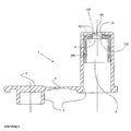
- the reaction vessel (1) in Figure 1 has substantially the dimensions of commercially available reaction vessels and is preferably similar to a 1.5 ml Standard reaction vessel made of polypropylene as it is manufactured in high volumes becomes. It has a breakthrough (in the context of the present invention as well Recess referred to (8,10), which is provided with a socket in which the Affinity matrix (100) can be inserted.
- the version generally includes a bearing surface (6, 11) for the affinity matrix (100), a Liquid breakthrough (8) to the surface-bound substance library (102) to bring into contact with the sample, as well as a visual breakthrough (10) to to allow the transmitted light detection.
- the breakthrough (8,10) be provided with an adhesive edge (7, 9) to the bonding of the affinity matrix in to simplify the reaction vessel (2).
- special quick-release closures can be provided become. The sealing effect can be achieved by seals.
- the reaction vessel can be closed by a cover (3).
- the incorporated into the socket affinity matrix (100) can be at different Positions are in the reaction vessel (2). So it is possible the affinity matrices as shown in Figures 1 to 4 at the bottom of the reaction vessel to Fasten. In this case, the affinity matrix (100) is always the sample substance exposed.
- the matrix can also be installed in the lid (3) become.
- the necessary conditioning steps of the sample are then included carried out upright reaction vessel (1), wherein the affinity matrix does not come into contact with the sample and is thus protected.
- the reaction vessel is then turned upside down, so that the sample with the surface-bound substance library (102) comes into contact. This would the thermal and chemical strains of the affinity matrix (100) reduce.
- the affinity matrices (100) can be used in different ways with the Reaction vessel (2) are connected.
- the affinity matrix from the outside in a liquid breakthrough (8) on a Edition (6) laid.
- adhesive edge (7) adhesive is given, which by flow and capillary action encloses the affinity matrix (100) and with the reaction vessel (2) liquid-tight and thermally stable connects
- the Affinity matrix (100) also with the reaction vessel (2), for example by laser welding be welded.
- the affinity matrix (100) thus becomes the Reaction vessel incorporated that the surface-bound substance library (102) can come into contact with the sample solution.
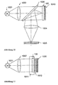
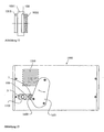
- After incorporation of the affinity matrix (100) is equivalent to an optical transmitted light detection with the readers (1000) Figures 5 to 15 possible.
- the affinity matrix (100) can also be incorporated from the inside, as in Figure 2 shown.
- the support surface and the Adhesive sand in the reaction chamber of the reaction vessel This has the advantage that the Affinity matrix (100) even at higher internal pressure, e.g. when used in one Centrifuge or when heating the sample liquid to temperatures near the Boiling point, the reaction space can not be pushed out of its holder.
- the assembly requires a higher cost.
- FIG 3 a variant is shown in which the affinity matrix (100) into a Chip carrier is installed. Subsequently, the chip carrier (200) on the Reaction vessel (2) pressed. Provide a clamp connection or thread (201) for a frictional and liquid-impermeable connection between Reaction vessel (2) and chip carrier (200).
- This variant combines the advantages of a from the inside inserted affinity matrix (100) in the reaction vessel with a simplified assembly.
- the disadvantage is another connection point like e.g. the clamping connection and the higher number of components.
- FIG 4 a variant is shown in which the affinity matrix (100) by an internally inserted clamping sleeve (300) between the reaction vessel (2) and Clamping sleeve (300) is clamped so that the bonding of the affinity matrix (100) with the reaction vessel (2) is unnecessary.
- this requires Execution a very high manufacturing precision of clamping sleeve (300) and Reaction vessel (2) to a liquid-tight clamping of the affinity matrix (100).
- the clamping sleeve (300) can in a further variant in the reaction vessel (2) are screwed.
- the targets to be examined may be in any type of sample, preferably in one biological sample.
- the targets become prior to their detection and quantification by the method of the invention isolated, purified, copied and / or amplified.
- the amplification is usually carried out by conventional PCR methods.
- the amplification is a multiplex PCR in a two-stage Process executed (see also WO 97/45559).
- a first stage becomes a Multiplex PCR was performed by using fusion primers whose 3 'ends are gene-specific and their 5 'ends represent a universal region. The latter is common to all forward and reverse primers used in the multiplex reaction equal.
- the amount of primer is limiting. Thereby All multiplex products can be up to a uniform molar level are amplified, provided that the number of cycles is sufficient for all Products Primer Limitation to achieve.
- a second stage become universal Present primers that are identical to the 5 'regions of the fusion primers. It Amplification takes place up to the desired amount of DNA.
- the detection is preferably carried out by in that the bound targets are provided with at least one marking, which in Step c) is detected.
- those on the probe array include arranged probe molecules that prove the molecular Interactions with the target molecules serve, at least one label and at least one predetermined breaking point, i. a labile or selectively fissile Binding that can be specifically destabilized or cleaved.
- the between the Marking and the position of the connection of the probes with the array surface arranged selectively cleavable bond allows the marking or detectable entity also for specific detection of molecular Interaction between probes and targets can be used. It is the Predetermined breaking point or selective cleavable bond within the probe molecule so positioned a breakage of the bond to peel off the detectable entity or the anchor group with the detectable entity from the array surface leads.
- the selectively cleavable bonds are preferred in this embodiment such that they are effectively fissile even if the probes at the Be immobilized array surface.
- the selectively cleavable bond can preferably selectively cleaved by chemical and / or physical methods become. An efficient cleavage on the surface is in particular due to agents to a lesser extent, such as atoms and ions.
- the labile bond therefore selectively cleavable by simple chemical agents, for example, by adding ions, more preferably acid anions, Base cations, fluoride and / or heavy metal ions such as mercury and / or Silver ions.
- the selectively cleavable linkage be in a nucleic acid that can be prepared by conventional DNA or RNA synthesis.
- the probe molecules of the probe array according to the invention particularly preferably comprise a nucleic acid of the formula A 1 -SA 2 , where S is a nucleic acid or a nucleotide unit which comprises at least one selectively cleavable bond, and A 1 and A 2 are any nucleic acids or Nucleic acid analogs are. Via one of the two nucleic acids or nucleic acid analogs A 1 and A 2 , the probe molecule is immobilized on the surface of the probe array according to the invention, while the other has at least one marker.
- S is preferably a nucleotide dimer bridged by a selectively cleavable bond.
- X and Y can be selected independently of one another from the group preferably consisting of O, NH and S, where X and Y are not simultaneously O.
- B stands for a nucleobase such as the purine derivatives adenine and guanine as well as the Pyrimidines Cytosine and thymine.
- the selectively cleavable bond within the nucleotide sequence of such Oligonucleotide probes is preferably a phosphorothioate linkage or a Phosphoramidate.
- the phosphothioate bond replaces i.e. a sugar O-P-S sugar bond has a phosphodiester bond, i. a Sugar-O-P-O-sugar bond of an unmodified oligonucleotide.
- a sugar O-P-S sugar bond has a phosphodiester bond, i. a Sugar-O-P-O-sugar bond of an unmodified oligonucleotide.
- a phosphothioate bond are two nucleosides by a phosphothioate bond connected.
- the selectively cleavable bond within the nucleotide sequence may also be another sulfur or nitrogen modified ester bond such as be a phosphonothioate bond.
- Binding can be used in the probe molecules. So can the selectively fissile Binding be cleaved, for example, photolytically selectively. nucleotide, which comprise a photolytically selectively cleavable bond and for the synthesis of Probe molecules of the probe array according to the invention can be used, are described for example in US 5,367,066, US 5,552,538 and US 5,578,717.
- RNA nucleotide building blocks comprising a chemically or physically selectively cleavable bond
- X and Y can be selected independently of one another from the group preferably consisting of O, NH and S, where X and Y are not simultaneously O, if PG is not a labile protecting group.
- PG is preferably selected from the group consisting of H and labile protecting groups such as
- B in formula II stands for a nucleobase such as the purine derivatives adenine and guanine as well as the pyrimidines cytosine and uracil.
- probe molecules with selectively cleavable bonds are stable under normal atmospheric, temperature, and light conditions.
- the labile bond is selectively through enzymatic methods cleavable.
- nucleotide building blocks such include labile bonds are described in US 4,775,619 and US 4,876,187.
- Enzymatic methods for cleavage of the selectively cleavable bond are however, less preferred within the scope of the present invention enzymatic activities due to the proximity of the selectively cleavable bond to Surface is severely hampered due to the immobilization of the probe molecules become. Consequently, an enzymatic cleavage reaction has only a very low Efficiency on, resulting in an undesirable high signal background incorrectly results in positive results.
- selectively cleavable bond can not be selectively cleaved by enzymatic methods.
- the selectively cleavable bond is located approximately midway between the location of the immobilization of the probe on the array surface and the position the marking of the probe. This will ensure that the probability the interaction of the target with the immobilized probe fragment, which the remainder of the probe remaining on the surface after bond cleavage corresponds, is substantially reduced or almost excluded. Is the however, selectively cleavable bond too close to the array surface, so is the Complex of probe and target molecule after cleavage is no longer sufficient stabilized, as the hybridization of the target with the at the surface of the array immobilized probe fragment is not stable enough. This would be too incorrectly lead to negative results.
- the label is attached to the targets or probes is coupled, preferably a detectable unit or via a Anchor group to the targets or probes coupled detectable entity.
- a detectable unit or via a Anchor group to the targets or probes coupled detectable entity.
- inventive method extremely flexible. So is the invention Processes with a variety of physical, chemical or biochemical Detection method compatible. The only requirement is that the detecting unit or structure directly to a probe or a target, for example, an oligonucleotide coupled or via a with the oligonucleotide Coupling anchor group can be linked.
- the detection of the label can be based on fluorescence, magnetism, charge, mass, Affinity, enzymatic activity, reactivity, gold labeling and the like. based.
- the label may be labeled using fluorophore Structures or building blocks based.
- the marker can be any of the targets or probes during or be coupled after their synthesis dye. Examples of these are cy dyes (Amersham Pharmacia Biotech, Uppsala, Sweden), Alexa Dyes, Texas Red, Fluorescein, rhodamine (Molecular Probes, Eugene, Oregon, USA), lanthanides such as Samarium, Ytterbium and Europium (EG & G, Wallac, Freiburg, Germany).
- fluorescent markers can be used in the context of the present invention as Marking or as a detection unit, which is coupled to the targets or probes, also luminescence markers, metal markers, enzyme markers, radioactive markers and / or polymeric markers are used.
- nucleic acid can be used as tag (tag), by Hybridization with a labeled reporter can be detected (sandwich hybridization). Use to prove the tag find various molecular biological detection reactions such as primer extension, ligation and RCA.
- anchor groups are biotin, digoxygenin and the like.
- the Anchor group are in a subsequent reaction with specific binding Components, such as streptavidin conjugates or antibody conjugates implemented, which are detectable themselves or trigger a detectable reaction.
- specific binding Components such as streptavidin conjugates or antibody conjugates implemented, which are detectable themselves or trigger a detectable reaction.
- anchor groups can be detectable in the implementation of anchor groups Units before, during or after addition of the sample comprising the targets or, if appropriate, before, during or after cleavage of the selectively cleavable bond in the probes respectively.
- the marking can according to the invention also by interaction of a labeled molecule with the probe molecules.
- the Labeling by hybridization of a labeled as described above Oligonucleotide with an oligonucleotide probe or an oligonucleotide target respectively.
- Detection method used which resulted in an adduct with a specific Solubility product, which has a precipitation result.
- substrates which are sparingly soluble, usually dyed product can be implemented.
- Labeling reaction enzymes are used, which are the turnover of a substrate in catalyze a sparingly soluble product.
- a number of eligible Reactions that are suitable to precipitate on array elements too lead, as well as possibilities for the detection of the precipitation are for example in International Patent Application WO 00/72018 and International Patent application WO 02/02810, the contents of which are expressly incorporated herein by reference Reference is made.
- the bound targets are provided with a mark that the Reaction of a soluble substrate to a sparingly soluble precipitate on the Array element catalyzes at which a probe / target interaction has taken place or as a seed for the conversion of a soluble substrate to a sparingly soluble precipitate on the array element acts on which a probe / target interaction has taken place.
- the use of the method according to the invention allows in this way simultaneous qualitative and quantitative analysis of a large number of probe / target interactions, wherein individual array elements with a size of ⁇ 1000 ⁇ m, preferably of ⁇ 100 microns and more preferably of ⁇ 50 microns are realized can.
- Arrays consists in the use of metal markings.
- metal markings for example colloidal gold or defined gold clusters coupled to the targets, possibly over certain mediator molecules such as streptavidin.
- the by the gold mark resulting staining is preferably by subsequent reaction with less noble Metals such as e.g. Silver reinforced, with the coupled with the targets Gold marking as a crystallization nucleus or catalyst, for example for the Reduction of silver ions to a silver precipitate acts.
- Gold marks coupled targets are also referred to as Gold conjugates called.
- the method according to the invention can also be a relative quantification of the probe / target interaction.
- the Ratio of bound target to gold particle 1 1.
- Embodiments of the present invention may be a multiple or even amount to a fraction of it.
- the detection in this embodiment of the invention Detection method is thus carried out by measuring the transmitted light absorption or Reflected reflection caused by the precipitate deposited on the Array elements where a probe / target interaction occurred, by the catalytic action of those coupled to the bound targets Mark is generated.
- the light absorption is in the case of the coupling of colloidal gold or defined gold cluster with the targets already by the presence of these caused by metallic markings.
- To enhance the light absorption is however, preferably catalytically by such interaction hybrids, i. those with a mark such as colloidal gold or defined Gold clusters provided targets, a non-transparent precipitate deposited.
- a non-transparent precipitate deposited.
- the following is the qualitative and / or quantitative detection of the probe / target interaction by measuring the transmitted light absorption by means of a Example explained.
- the following is described Do not proceed to the silver / gold coloration described above limited, but can be applied accordingly to all detection methods in which the bound targets are marked with the reaction of a soluble substrate to a sparingly soluble precipitate catalyzes the array element at which a probe / target interaction has taken place or as a seed for the conversion of a soluble substrate to a sparingly soluble precipitate on the array element acts on which a probe / target interaction has taken place.
- the target molecule is e.g. biotinylated by PCR.
- the PCR product is against a substance library (102), for example a DNA library, hybridized.
- the reaction vessel (1) according to the invention Streptavidin-functionalized gold beads added to those biotinylated Hybrids, such as DNA hybrids react.
- the Surface bound gold beads can be produced a silver precipitate, by, for example, silver nitrate with hydroquinone under the catalytic action of gold (see, inter alia, WO 00/72018, DE 100 33 334.6, M. A. Hayat, Immunogold-Silver Staining, CRC Press, New York, 1995).
- I is the light intensity after absorption
- I 0 is the light intensity before absorption
- a is an absorption coefficient multiplied by the shading per unit area b by the silver precipitate.
- the measured quantities are intensity I and time t. These measured quantities are obtained by illuminating the carrier element with the substance library and recording the transmitted light with a camera (see Figure 19). This photograph is repeated at regular intervals while the silver deposition is carried out. The brightness values of the individual library regions (spots) are evaluated for each shot, whereby the intensity I of each spot is obtained. These brightness values can be automatically calculated using standard software, such as IconoClust® (Clondiag, Jena, Germany). By plotting I / I 0 against time t, the curves shown in Figure 20 are obtained. The Lambert-Beer law corresponding to the equation (I) can be related to the silver deposition time series thus obtained in the following manner.
- the shading per unit area b by the silver precipitate is proportional to the number of silver beads per unit area N, the shading area per silver bead F, and a constant k .
- N N * F * k
- I i I 0 i * (exp ( -a ' i * t 2 ) + exp ( -a ' H * t 2 )) + O i .
- O is a device-dependent offset value.
- the number of gold beads deposited per unit area depends on the one hand on the amount of gold globules marked targets and on the other hand of the binding strength of the targets, for example the target DNA, with the Probes, for example, the spot DNA from. If there is no target in the sample, the it interacts with a probe on the corresponding array element also not for the deposition of gold globules on the surface of this array element or spots. If the bond between probe and target is weak, so There will be very few gold beads on the surface of this array element drop.
- a' represents a measure of the concentration of the target DNA and the binding strength of the target DNA on the array element or spot i da.
- Figure 20 shows the silver deposition time series of two spots hybridized against a target DNA.
- the DNA probes of the spots differ by one base so that the target DNA is perfectly complementary to the probe of one spot while mismatching with the probe of the other spot.
- the silver absorption constant a ' can be calculated from the two measurement curves by non-linear regression using equation (VI). In the case of the Perfect Match it is 2.566 x 10 -6 sec -2 and in the case of the mismatch 4.83 x 10 -7 sec -2 (see also Example 2).
- the two constants differ by almost a power of ten.
- the calculation of the constant a ' can be used as a significant measure of the binding strength and the concentration of the target DNA at a spot.
- the regression can be used to determine I 0 and O as further parameters.
- I 0 illumination inhomogeneities of the DNA library can be corrected.
- a flat field correction of all further images taken for the time series at a later time can be undertaken.
- the validity of a measurement can be estimated by means of parameter O.
- Method is thus in step c) the time course of precipitation formation the array elements detected in the form of signal intensities. In this way can be an accurate determination of the relative quantitative amount of bound Targets are guaranteed. Such an approach is detailed in the international patent application WO 02/02810.
- the targets are preferably with markings provided that the reaction of a soluble substrate to a sparingly soluble Precipitate on the array element where a probe / target interaction has occurred, catalyze, or crystallization for such reactions Act.
- the targets be provided directly with such markings.
- Another preferred way of coupling the targets with a label represents the synthetic or enzymatic addition of a homopolymeric region,
- a polyA sequence to the targets to form a continuous sequence as described for example in US 6,103,474.
- labeling is preferably by sandwich hybridization labeled with a complementary to the homopolymer sequence Oligonucleotide with the variations described above.
- a signal amplification by amplification of parts of the target attached homopolymer sequence with simultaneous incorporation of labeled bases especially preferred via an RCA mechanism by using a circular single-stranded templates that complement the Homopolymer sequence.
- the targets are with a catalyst, preferably provided an enzyme, the conversion of a catalyzed soluble substrate in an insoluble product.
- the reaction to the Forming a precipitate on the array elements leads in this case to the Conversion of a soluble substrate into an insoluble product in the presence of a catalyst coupled to the targets, preferably enzyme.
- the enzyme will preferably selected from the group consisting of horseradish peroxidase, alkaline phosphatase and glucose oxidase.
- the soluble substrate becomes preferably selected from the group consisting of 3,3'-diaminobenzidine, 4-chloro-1-naphthol, 3-amino-9-ethylcarbazole, p-phenylenediamine HCl / pyrocatechol, 3,3 ', 5,5'-tetramethylbenzidine, naphthol / pyronine, bromochloroindoyl phosphate, Nitrotetraazolium blue and phenazine methosulfate.
- a colorless soluble hydrogen donor e.g. 3,3'-diaminobenzidine
- the enzyme Horseradish peroxidase transfers hydrogen ions from the donors Hydrogen peroxide to form water.
- a precipitate on the array elements is the Reaction that leads to the formation of a precipitate on the array elements, the Formation of a metallic precipitate.
- a silver compound preferably silver nitrate, silver lactate, Silver acetate or silver tartrate, to elemental silver.
- a reducing agent preferably formaldehyde and / or hydroquinone used.
- the precipitation of the metallic compound takes place in The presence of metal clusters or colloidal clusters coupled to the targets Metal particles, in particular gold clusters or colloidal gold particles. That in In this case, the metal clusters or colloidal metal particles with the Targets coupled markers dar.
- metal clusters or colloidal metal particles with the Targets coupled markers dar.
- silver nitrate in implemented elemental silver wherein silver ions from the solution of gold as Incubate seed and in a second step with the help of a Reducing agent such. Formaldehyde or hydroquinone can be reduced. This results in an insoluble precipitate of elemental silver.
- the precipitation of the metallic takes place Compound in the presence of polyanions coupled to the targets. If it If the target itself is not a poly anion, then there is the Possibility to use such for nucleation. That with a poly-anion For example, labeled target is exposed to a silver nitrate solution. Store it the silver cations on the poly-anion selectively. After that, be with one Reducing agent converted silver ions into elemental silver.
- the coupling of enzymes or catalysts or metal clusters or colloidal Metal particles or polyanions to the targets can be directly or via to the targets coupled anchor molecules take place. Basically there is no need that Target directly with the markers described above. It exists also the possibility of using suitable anchor molecules, e.g. Streptavidin, attached to the Target coupled, a subsequent coupling of the marker to to reach.
- suitable anchor molecules e.g. Streptavidin
- a conjugate consisting of the respective catalyst or crystallization seed and a specific binding partner for the anchor molecule also allows the Implementation of the procedures described above.
- the reaction leading to education precipitation at the array elements, then the bond of a specific binding partner to an anchor molecule coupled to the target represents.
- binding partner / anchor molecule pairs are preferably selected from the group consisting of biotin / avidin or streptavidin or anti-biotin antibodies, Digoxigenin / Antidigoxigenin Immunoglobulin, FITC / Anti-FITC Immunoglobulin and DNP / anti-DNP immunoglobulin.
- catalytically soluble substrate converted into an insoluble and precipitating product. by virtue of Close to the surface, the product becomes directly on the surface deposited and forms a solid, insensitive to various washes Rainfall.
- the Markers in particular the enzymes or metal clusters or colloidal ones Metal particles or polyanions, to the targets before, during or after the Interaction can be coupled with the probes.
- the interaction between the target and the probe is a hybridization between two nucleotide sequences.
- the hybridization of the targets with the probes arranged on a probe array takes place according to one of the known standard protocols (see, inter alia, Lottspeich and Zorbas, 1998).
- the resulting hybrids can be stabilized by covalent bonding, for example via psoralen intercalation and subsequent cross-linking, or as described in US Pat. No. 4,599,303, by noncovalent binding, for example by binding of intercalators.
- the interaction between the target and the probe is one Reaction between an antigenic structure and the corresponding antibody or a hypervariable section thereof or a reaction between a receptor and a corresponding ligand.
- the binding or recognition of targets by specific probes is common a spontaneous non-covalent reaction under optimal conditions. Of which includes are also non-covalent chemical bonds.
- the composition of the Medium and other chemical and physical factors affect the Speed and strength of binding. Thus, for example, at the Nucleic acid detection has a lower stringency and higher temperatures Rate and strength of bond between two not perfectly complementary strands.
- the optimization of the binding conditions is for antigen / antibody or Ligand / receptor interactions also required However, binding conditions are usually less specific.
- Evidence of the presence of a precipitate on an array element is made in one embodiment of the present invention by reflection, absorption or diffusion of a light beam, preferably a laser beam or a LED, by the precipitation. Modified due to its granular form the precipitate is the reflection of a ray of light. Furthermore, the precipitation leads to a strong light diffusion through conventional detection devices can be recorded. If the precipitation such as the Silver precipitate appears as a dark surface, can also reduce the absorption of Light detected and recorded. The resolution of the detection then depends from the number of pixels of the camera.
- detection of the presence of a precipitate occurs an array element in which the light source scanning the array elements with a Sampling speed is homogeneously illuminated, the scanning speed particularly preferably ensures that an exposure time of the receiving Camera all signals of the sample combined into one image.
- the detection of the amplified by the specific reaction Areas by means of a very simple optical structure in transmitted light (contrast by shading) or reflected light (contrast by reflection).
- the Detected intensity of the shaded area is directly proportional to Occupancy density with markings such as gold particles and the Nucleation state of the particles.
- the electrical measurements can be made by means of conductivity measurements Microelectrode array arrangements or via an array of Micro capacitance sensors or via potential measurements by means of field-effect transistor arrays (FET arrays) take place.
- FET arrays field-effect transistor arrays
- For conductivity measurements by means of Microelectrodes will change the electrical resistance between two Electrodes in a deposition reaction (E. Braun, Y. Eichen, U. Sivan, G. Ben-Yoseph, Nature, 775, vol 391, 1998).
- For dielectric measurements with Microcapacity sensors will change the capacity of two to each other arranged electrodes (M. Madou, Fundamentals of Microfabrication, CRC Press, Boca Raton, 1997).
- For potential measurements using FET arrays the Change in the potential on the sensor surfaces measured (M. Madou, Fundamentals of Microfabrication, CRC Press, Boca Raton, 1997).
- the Evidence of the presence of a precipitate on an array element Scanning Electron Microscopy, Electron Probe Microanalysis (EPMA), Magneto-optical Kerr microscopy, magnetic force microscopy (MFM), atomic force microscopy (AFM), measurement of the mirage effect, scanning tunneling microscopy (STM) and / or ultrasound reflection tomography.
- EPMA Electron Probe Microanalysis
- MFM magnetic force microscopy
- AFM atomic force microscopy
- STM scanning tunneling microscopy
- STM scanning tunneling microscopy
- magneto-optical Kerr microscopy When using a substrate that is magnetic or with magnetic particles Marked, the detection of the reaction by magneto-optical Kerr microscopy or MFM.
- magneto-optic Kerr microscopy is the rotation of the polarization plane of the light by magnetic fields (Kerr and Faraday effect) (A. Hubert, R. Shufer, Magnetic Domains, Springer, 1998).
- the change in optical density through the substrate on the surface as a result of Reaction can be detected by means of the Mirrage effect.
- Mirrage effect is the local heating of a surface by absorption of a bundled Laser beam over the associated refractive index change measured. By Scanning the surface gives you a picture of the local Surface Absorption Properties (A. Mandelis, Progress in Photothermal and Photoacoustic Science and Technology, Volume 1, Elsevier, New York 1992).
- One Another thermal spatially resolved method for the detection of Interaction reaction through the substrate is an array arrangement of Microthermophiles containing the enthalpies of crystallization of the Substrate deposits (J.M. Köhler, M. Zieren, Thermochimica acta, 25, vol 310, 1998).
- STM and AFM are also suitable for detecting reaction by substrate.
- AFM atomic force microscope
- a micro- or nano-tip feels its way Surfaces, thereby measuring the surface topography (E. Braun, Y. Eichen, U. Sivan, G. Ben-Yoseph, Nature, 775, vol 391, 1998).
- the magnetic force microscope MFM detects local magnetic via a nanotip Susceptibility differences (A.Hubert, R. Schfer, Magnetic Domains, Springer, 1998).
- the scanning tunneling microscop STM the nano tip of the Tunnel current measured to determine nano-surface topography (O. Marti, M. Amrein, STM and SFM in biology, Academic Press Inc., San Diego, 1993)
- Exotic procedures such as ultrasound reflection tomography can also be used.
- the tomographies are Procedures in which a 3-dimensional picture is collected piecemeal (F. Natterer, Mathematical Methods of Computer Tomography, Westdt. Vlg., Wiesbaden, 1997).
- the Measurement of the ultrasound reflection used to generate the tomogram V. Fleischer, F. Bergner, DGZfP NDT Conference Dresden 1997.
- the device according to the invention in a detection method used, as described above, the detection of a reaction takes place, which leads to a precipitation at the array elements, where a Interaction between probes and targets has taken place.
- Reaction vessel used in the detection device or the reader can be formed on some array elements due to the specific Interaction of the sample or the target with the probes Interaction products in the form of a precipitate. These Interaction products have a different absorption coefficient than the pure substances. By appropriate reactions, this effect can be significantly enhanced as described above.
- the detection device is preferably a camera, in particular a CCD or CMOS camera or similar cameras, usually the entire Area of the probe array records. Alternatively, you can also scan Method for the detection device for reading the reaction vessel be used.
- the device according to the invention comprises Detection device additionally a readout optics.
- the device according to the invention comprises additionally at least one light source.
- a light source in the context of The present invention preferably ensures a homogeneous illumination of the Carrier.
- the light source is selected from the group, consisting of lasers, light-emitting diodes (LED), surface radiators and High pressure lamps.
- a homogeneous illumination of the carrier can in this embodiment, be ensured by the fact that the light source is more diffuse radiating light sources, their superposition in a homogeneous Lighting results.
- diffuse-scattering LEDs which allow are arranged in a matrix, a homogeneous at short distances to the sample Lighting.
- the homogeneity of the lighting can be also by an appropriate Structuring of the lid of the reaction vessel according to the invention achieved become. In this way, the lid of the invention takes over Reaction vessel the function of a lens.
- the light source is in a Swivel arm installed, which is used to insert the reaction vessel into the device can be swung to the side. Then he is on the reaction vessel pivotable to illuminate the affinity matrix. That way that can Reaction vessel are pressed into a reaction vessel holder, so that the Substance library is in the correct image plane. A refocusing The imaging optics or readout optics is thereby superfluous. Alternatively, you can the reading device or the detection device with a focusing device be equipped to accommodate different types of reaction vessels to be able to.
- a Justiervertiefung pressed into the lid of the reaction vessel can be. This avoids distortion of the affinity matrix.
- the components of an exemplary construction of an inventive Apparatus for the optical detection of a precipitate formation consist of a low power (500 mcd) light source, e.g. an LED, to the homogeneous Lighting and a detector, e.g. a CCD camera. Due to the Enhancement effect on the catalytic deposition of the substrate, in particular When using a gold / silver system, the changes are the optical Properties of the surface are so pronounced that a simple flatbed scanner, a slide scanner or similar device for the detection of precipitation sufficient.
- a low power (500 mcd) light source e.g. an LED
- a detector e.g. a CCD camera
- Typical detection times are well under one second, while comparable sensitive CCD systems for the detection of fluorescence about 10-18 Seconds, so that inexpensive consumer cameras are used whose signal transmission corresponds to the video standard.
- the device additionally includes optical filters.
- Such filters allow for one is the spectral confinement of homogeneous illumination and the other the Illumination of samples with different wavelengths.
- the device according to the invention additionally comprises filter changer. With These filter changers, the optical filters can be changed quickly and thus possible misinformation, e.g. due to contamination, be clearly recognized and eliminated.
- the device additionally comprises a semipermeable Mirror between light source and carrier element.
- a semipermeable Mirror between light source and carrier element.
- a surface mirror on the underside of the support element is located in a preferred embodiment for measuring the reflectivity.
- a surface mirror on the underside of the support element is located in this embodiment.
- the sample is in a cuvette, the by means of a read-out optics direct contact to the sensor of a CCD camera Has.
- the readout optics or the coupling medium is between the cuvette and camera preferably a fiberboard, available for example from the company Schott, or a picture cable.
- the inventive Reaction vessel a cuvette of two plane-parallel plates with intermediate sample volume. The chip with the surface-bound Substance library is used in this cuvette and can be similar to cuvettes in be read out a spectrometer.
- the device according to the invention additionally has a temperature control unit which ensures that the sample is during the Measurement is stored temperature stable. This ensures the reproducibility the Results.
- reaction vessels are in the Device arranged so that ensures a sequential detection is. For example, a time-shifted, consecutive reading by Arrangement of the samples in the form of magazines or a carousel in the Device to be achieved according to the invention.
- a group of Pixels understood to be an illustration of the measured signal intensities for represents a probe array and directly to, for example, a screen or a printer can be sent for recording.
- the dynamic Resolution of the measurement data even when using an 8-bit detection technique extremely increase.
- the structure of a device necessary for this differs through the mechanical uptake of a reaction chamber and a modified one Acquisition software.
- the software for example the software Iconoclust® (Clondiag), is characterized by the successive processing Recordings allowed. For this, the over the individual Probe array elements determined gray values at each time. For all Array elements becomes the virtual signal intensity depending on the precipitation formation calculated from the time.
- Miniatur Deutschenspotential of such a structure is very high, so that the entire system designed as an autonomous hand-held device for field use can. Furthermore, the device according to the invention in a particular preferred embodiment realized as a highly integrated autonomous unit become. Thus, highly sensitive applications of micro-arrays such as e.g. medical diagnostics, forensics, bacterial screening and the like independent of lay medical or biological laboratories.
- the reaction vessel according to the invention thus comprises a standard laboratory reaction vessel or standard microtube with one at one of the base areas, z. At the top or in the lid of a conventional reaction vessel, e.g. a commercial Eppendorff tube, inserted carrier or array.
- a conventional reaction vessel e.g. a commercial Eppendorff tube, inserted carrier or array.
- This design allows a much easier handling and a higher Reproducibility. Solutions can easily in the inventive Be pipetted and used in almost every especially in molecular biological laboratories existing Microtube equipment incubated and processed, for. B. be centrifuged.
- Figures 5 to 12 illustrate various optical principles, for reading surface-bound substance libraries (102) can be used.
- the detection or Reader finds a specific interaction of the sample or of the target with probes of some library members of the substance library (102) instead, causing interaction products to form on some surfaces.
- FIGs 5 to 12 were used to better illustrate the Auslesekins the representation of the reaction vessel (1) on the representation of surface-bound substance library (100).
- FIGs 13 to 17 are two concrete embodiments for mapping a precipitate on surface-bound substance libraries (100).
- Imaged reading devices (1000) can also scan methods for reading the Reaction vessel (1) are used.
- Figure 5 to 17 is based on Use of DNA chips (100) in conjunction with the one described above Silver deposition reaction, but is of course not limited to these.
- FIG 5 is the basic arrangement of the device according to the invention for reading the reaction vessel (1) shown.
- Light of an incoherent Light source (1001) illuminates by means of a lighting optical system (1002) surface-bound DNA library on a library chip (100), the in a tube (1).
- a readout optics (1004) the signal becomes taken by a CCD camera (1005).
- Figure 6 shows the same arrangement as that of Figure 5, with the Variant, by introducing optical filters (1006) in the Illumination beam path to narrow the spectral range of illumination.
- Light from an incoherent light source (1001) illuminates by means of illumination optics (1002) the surface-bound DNA library on a library chip (100) out, which is located in a reaction vessel (1).
- illumination optics (1002) illuminates by means of illumination optics (1002) the surface-bound DNA library on a library chip (100) out, which is located in a reaction vessel (1).
- readout optics (1004) the signal is picked up by a CCD camera (1005).
- the possibility, to quickly change this filter by means of filter changer (1007), has for the Evaluate the benefit, possible misinformation, e.g. by Impurities occur, clearly detect and eliminate.
- the point light source (1001) is passing through replaced a lighting array (1008).
- Light of a lighting array (1008) lights up by means of illumination optics (1002) the surface-bound DNA library (102) on a library chip (100) located in a reaction vessel (1) is homogeneous.
- the signal from a CCD camera (1005) taken.
- a compact reader 1000
- the CCD sensor (1005) of the camera is contacted directly with the affinity matrix (100).
- This contact can also by the use of a fiberboard (1012) or at even greater distances through A picture guide cable can be made if direct contact is not possible is.
- Light of an incoherent light source 1001 lights up by means of a Illumination optics (1002) the surface-bound DNA library on a Libraries chip (100) located in a reaction vessel (1).
- the Signal from the sample is taken directly from a CCD camera (1005).
- the samples are reflected light measure.
- the reflectivity of the DNA library (102) measured.
- Light from an incoherent light source (1001) is lit. by means of a lighting optical system (1002) through a semitransparent mirror the surface-bound DNA library on a library chip (100), the is in a reaction vessel (1).
- the half-transparent mirror (1009) the reflected signal is redirected to the readout optics (1004) and canceled by this is shown on a CCD camera (1005).
- Incident light measurements are advantageous in the arrangement shown in FIG.
- Light one incoherent light source (1001) illuminates by means of illumination optics (1002) through a semitransparent mirror, the surface-bound DNA library (102) on a library chip (100) located in a reaction vessel (1) located.
- the semitransparent mirror (1009) Through the semitransparent mirror (1009), the reflected signal on the readout optics (1004) deflected and from this to a CCD camera (1005) displayed.
- the disadvantage of poor reflection of the sample is due to Transmission effects complemented by the illumination light through a mirror layer (1010) behind the sample, either as a separate mirror or as on the Back of the sample carrier applied layer, is reflected.
- Figure 11 shows the possible arrangement of the device according to the invention in a transparent sample space, preferably in a cuvette (1011) through the optically plan outer surfaces a good coupling of the receiver by means of Allow fiber board (1012) to the sample space.
- Light of an incoherent Light source (1001) illuminates by means of a lighting optical system (1002) transparent wall of the cuvette on the surface-bound DNA library (102) a library chip (100).
- a lighting optical system 1002
- transparent wall of the cuvette becomes the signal from the sample is taken directly from a CCD camera (1005).
- Coupling medium between cuvette and CCD camera can be a fiber board (1012) or an image guide cable can be used.
- the device shown in Figure 12 provides a very compact arrangement of the reader (1000) shown in Figure 11.
- diffuse area radiators (1013) e.g. on electroluminescence or Cold cathode fluorescence methods are based
- the signal of the sample is taken directly from a CCD camera (1005) taken.
- FIGs 13 and 14 an embodiment in the plan and as Sectional drawing of a reader (1000) shown.
- the working principle corresponds that of the device shown in Figure 1.
- a deflection mirror was installed between the affinity matrix (100) and the imaging optics (1004).
- the light from the light source (1008) lights up in the reaction vessel (1) and then through the DNA chip (100) to a Deflecting mirror. From there, the image of the DNA chip (100) over the Imaging optics (1004) projected onto a CCD camera (1005).
- the light source (1008) consists of light emitting diodes, which are built into a swivel arm, which is used for Insertion of the reaction vessel (1) in the reader (1000) pivoted to the side can be.
- Figure 15 shows a reader (1000) that is different from the one in the Figure 13 differs in that the swivel arm (1101) by a Slider (1300) is replaced.
- the slide (1300) is driven by a linear bearing (1310) pushed over the reaction vessel (1).
- a carriage (1320) pushes through four Compression springs (1321) the reaction vessel (1) in the reaction vessel holder (1100).
- One Justierspalt (1322) engages around the lid (3) of the reaction vessel (1) such that by the sliding movement of the slide (1300), the reaction vessel (1) in his correct position is rotated and fixed.
- Figure 17 shows the location of the Slider (1300) to the reaction vessel (1) with the reader open.
- the Carriage (1300) moves along the arrow shown there and closes characterized the the reaction vessel (1).
- the light source (1008) over the reaction vessel (1) pushed so that measured with the reader (1000) can be.
- the carriage (1320) lies between
- the carriage therefore has a Detedgingmaschineffuung (1323) to illuminate the affinity matrix (100) can.
- Example 2 Detection and Specificity of the Hybridization of Nucleic Acids in Reaction vessel (1) by means of silver detection
- the human cyp2D6 gene encodes a human cytochrome P450. This enzyme plays an important role in the metabolism of various drugs and drugs. Mutations in the cyp2D6 gene can lead to hypersensitivity or intolerance to certain drugs. At least 14 such mutations (point mutations and deletions) are described for cyp2D6 . For a selection of these mutations (G1749C, dT1795, G1934A, G2064A) it should be tested whether the respective wild type or mutation is present in a sample to be analyzed.
- epoxidized glass surface (slide size: 75 mm x 25 mm) (101) were used with a MicroGrid II arrayer (BioRobotics, Cambridge, Great Britain) 40 amino-modified oligonucleotides (probes) with a length of 21-25 nucleotides deposited at defined sites and covalently immobilized (Library or array elements).
- the probes were divided into pairs of Library elements, the first being wild-type and the second being the wild-type Represents mutation.
- sequences of the oligonucleotides were as follows (sequence in 5'-3 'direction with 5'-NH 2 modification):
- Each of the 40 oligonucleotide probes was in triple repetition on the DNA library (102) filed (to the arrangement for the library elements, see Figure 18).
- the library elements had one Distance of 0.2 mm, the entire DNA library (102) covered an area of 2.4mm x 2.4mm. Overall, this allowed more than 100 slides per slide identical DNA libraries (102) are generated.
- each of the chips (100) contained exactly one 2.4 mm x 2.4 mm DNA library (102). Subsequently, the chips (100) were inserted into the reaction vessel (1) in the manner shown in Figure 1 and glued with polydimethylsiloxane, which was placed in the adhesive edge (7).
- the chip (100) in the reaction vessel (1) for 10 min in 2x SSC / 0.2% SDS (500 ul at 30 ° C), 2x SSC (500 ul at 20 ° C) and 0.2x SSC (500 ⁇ l at 20 ° C) with shaking.
- the reader (1000) consists of a sample holder with Temperature control, the readout distance and a swivel arm (1101) with the Lighting (see figures 13 and 14).
- the samples were in transmission Illuminated by means of a diffused luminous array of several LED (1008).
- One additional diffuser allowed the homogeneous illumination of the samples Deviations of less than 10% from the maximum.
- the sample was read in transmission.
- the samples were in the provided recording inserted.
- the storage accuracy of the samples was ensured by a special shape of the receptacle (1102).
- the Reaction vessel (1) inserted with open closure.
- the lid of the Reaction vessel (1) leaves in this position no twists of Affinity matrix (100) too. Only in Lagerinter is the swinging the Illumination into the measuring position possible. In the measuring position fixes the Swivel arm simultaneously the reaction vessel (1) and thus the affinity matrix.
- the silver developing solution was prepared by mixing equal parts of initiator and enhancer solution. During the 20 minute incubation at 25 ° C ( ⁇ 0.1 ° C) was the time course of silver amplification through a series of photos (all 10 s a picture) documented (see Figure 19)
- Figure 20 shows the time series for element G1934A + 4 (mutation) and G2064A-WT (wild-type).
- a reaction vessel (2) In the bottom of a reaction vessel (2) has an opening or a recess (8) is incorporated with a support surface (6) on which the affinity matrix (100) can be placed from the outside.
- the affinity matrix (100) is bonded by placing the adhesive in a suitable adhesive tape (7).
- a reaction vessel (2) In the bottom of a reaction vessel (2) has an opening (10) is incorporated with a support surface (11) on which the affinity matrix (100) can be placed from the inside.
- the affinity matrix (100) is bonded by placing the adhesive in a designated adhesive tape (9).
- the bottom of a reaction vessel (2) is connected to a clamping connection (201) Mistake.
- a chip carrier (200) On this clamping connection (201), a chip carrier (200) be pressed liquid-tight.
- the chip carrier has an opening (10), placed in the affinity matrix (100) on a support surface provided for this purpose and then can be glued.
- the affinity matrix (100) becomes between the reaction vessel (2) and a clamping sleeve (300) liquid-tight jammed, so that a bond is not absolutely necessary.
- Figure 5 shows a basic arrangement for reading an array in the reaction vessel according to the invention.
- Light from an incoherent light source (1001) illuminates the surface-bound DNA library by means of illumination optics (1002) on a library chip (100), which is in a tube, homogeneous.
- illumination optics (1002) illuminates the surface-bound DNA library by means of illumination optics (1002) on a library chip (100), which is in a tube, homogeneous.
- a readout optics (1004) the signal from a CCD camera (1005).
- Figure 6 shows the same arrangement as Figure 5, with the variant by Introducing optical filters (1006) into the illumination beam path to narrow the spectral range of lighting.
- optical filters 1006
- the possibility of this filter quick to change by means of filter changer (1007) has the Advantage, possible misinformation, e.g. due to contamination, clearly recognizable and eliminate.
- the classic lighting is through Illumination array (1008) replaced.
- Illumination array 1008
- diffusely scattering LED, matrix-shaped arranged allow a homogeneous at short distances to the sample Lighting.
- Figure 8 shows a compact form of the arrangement of Figure 1, in which the CCD sensor (1005) of the camera directly with the affinity matrix (100) is contacted. This contact can also be achieved by using a fiber board (1012). or be made at even greater distances by a Schmleittiv, if direct contact is not possible.
- Figure 9 shows an arrangement for reading the samples in incident light.
- a semi-transparent mirror (1009) is used.
- Figure 11 shows an arrangement in a transparent sample space, preferably in a cuvette (1011) passing through the optically planar outer surfaces a good coupling of the receiver by means of fiber board (1012) to the sample space enable.
- diffuse surface radiators (1013) e.g. on Electroluminescent or cold cathode fluorescence methods are based, can be realize very compact sensors, as shown in Figure 8.
- Figure 12 shows a very compact arrangement of the one shown in Figure 11 illustrated reading device (1000).
- Sectional drawing of a reader which corresponds to the one in Figure 7 illustrated principle works, with the difference that between the Affinity matrix (100) and the imaging optics (1004) a deflection mirror was installed in order to come to compact device dimensions.
- the light source (1008) consists of light emitting diodes, which are installed in a pivot arm (1101), the to insert the reaction vessel (1) in the reader to the side swung can. Thereafter, it is pivoted over the reaction vessel (1) to the To illuminate affinity matrix (100).
- Figure 14 corresponds to Figure 13, only as a top view (from the operator side). On the top there is a Justierverkiefung (1102), in which the lid of the Reaction vessel (1) is pressed. This will cause a twist of the Affinity matrix avoided.
- a reader (1000) is shown that is different from the one shown in Figure 13 characterized in that the pivot arm (1101) by a slide (1300) is replaced.
- the slide (1300) is a linear bearing (1310) on the Pushed reaction vessel (1).
- a carriage (1320) presses the reaction vessel (1) into the reaction vessel holder (1100).
- the carriage (1320) of the slider (1300) is shown in plan view.
- the sled (1320) is pressed by four compression springs (1321) on the reaction vessel (1).
- One Justierspalt (1322) engages around the lid (3) of the reaction vessel (1) such that the Reaction vessel (1) is rotated in its correct position and fixed.
- the position of the slide (1300) is in cross section for Reaction vessel (1) shown with the reader open.
- the carriage (1300) moves along the arrow and thereby closes the reader.
- the slide consists of the compression springs (1321) which press down the carriage (1320), the one Detection opening (1323) through which the light of the light source (1001) can radiate.
Landscapes
- Health & Medical Sciences (AREA)
- Chemical & Material Sciences (AREA)
- Life Sciences & Earth Sciences (AREA)
- Immunology (AREA)
- General Health & Medical Sciences (AREA)
- Engineering & Computer Science (AREA)
- Analytical Chemistry (AREA)
- Biochemistry (AREA)
- Physics & Mathematics (AREA)
- Molecular Biology (AREA)
- Hematology (AREA)
- Organic Chemistry (AREA)
- Clinical Laboratory Science (AREA)
- Chemical Kinetics & Catalysis (AREA)
- Proteomics, Peptides & Aminoacids (AREA)
- Wood Science & Technology (AREA)
- Zoology (AREA)
- Biotechnology (AREA)
- Microbiology (AREA)
- Pathology (AREA)
- Biomedical Technology (AREA)
- General Physics & Mathematics (AREA)
- Urology & Nephrology (AREA)
- Bioinformatics & Cheminformatics (AREA)
- Genetics & Genomics (AREA)
- General Engineering & Computer Science (AREA)
- Biophysics (AREA)
- Cell Biology (AREA)
- Food Science & Technology (AREA)
- Medicinal Chemistry (AREA)
- Spectroscopy & Molecular Physics (AREA)
- Apparatus Associated With Microorganisms And Enzymes (AREA)
- Measuring Or Testing Involving Enzymes Or Micro-Organisms (AREA)
- Investigating Or Analysing Materials By Optical Means (AREA)
- Investigating Or Analyzing Non-Biological Materials By The Use Of Chemical Means (AREA)
- Physical Or Chemical Processes And Apparatus (AREA)
- Superconductors And Manufacturing Methods Therefor (AREA)
- Signal Processing For Digital Recording And Reproducing (AREA)
- Analysing Materials By The Use Of Radiation (AREA)
- Mechanical Treatment Of Semiconductor (AREA)
Claims (37)
- Récipient réacteur pour prouver l'interaction spécifique entre des molécules moléculaires cible et de sonde, dans lequel il s'agit d'un tube présentant une forme et une taille typiques et présentant une capacité de remplissage de 100 µl à 2,5 ml, dans lequel un élément support (100) est disposé sur l'une de ses surfaces de base, comportant des molécules de sonde immobilisées dans des zones prédéfinies.
- Récipient réacteur selon la revendication 1,
caractérisé en ce que la surface de base du récipient réacteur de laboratoire présente un évidement pour recevoir l'élément support. - Récipient réacteur selon la revendication 1 ou 2,
caractérisé en ce que l'élément support est optiquement perméable dans la zone d'une surface de détection. - Récipient réacteur selon l'une quelconque des revendications précédentes,
caractérisé en ce que la surface de base figurant en face de la surface de détection est optiquement transparente. - Récipient réacteur selon l'une quelconque des revendications précédentes,
caractérisé en ce que le matériau de l'élément support est du verre et/ou du silicium et, de préférence, sélectionné dans le groupe se composant de Borofloat 33, de verre de quartz, de CaF2 monocristallin et de silicium monocristallin. - Récipient réacteur selon l'une quelconque des revendications précédentes,
caractérisé en ce que le matériau du récipient est sélectionné dans le groupe se composant du verre, de la céramique de verre, de verre recouvert de matière plastique, de matières plastiques tels que le polypropylène, le polyéthylène, le polystyrol, le polycarbonate, le PVC, le polyméthylméthacrylate, de matières plastiques à base de silicone, le caoutchouc, le polytétrafluoréthylène et/ou le Nylon et des métaux tels que les aciers inoxydables, le platine et/ou l'aluminium. - Récipient réacteur selon l'une quelconque des revendications précédentes,
caractérisé en ce qu'il présente un volume de remplissage de 1,5 ml. - Récipient réacteur selon l'une quelconque des revendications précédentes,
caractérisé en ce que dans le cas des molécules de sonde immobilisées, il s'agit d'une bibliothèque de substances sélectionnée dans le groupe se composant de bibliothèques de protéines, de bibliothèques de peptides et de bibliothèques d'acides nucléiques. - Récipient réacteur selon la revendication 8,
caractérisé en ce que la bibliothèque de protéines est une bibliothèque d'anticorps, une bibliothèque de protéines de récepteur et/ou une bibliothèque de protéines de membrane. - Récipient réacteur selon la revendication 8,
caractérisé en ce que la bibliothèque de peptides est une bibliothèque de ligands de récepteur, une bibliothèque de peptides pharmacologiquement actifs et/ou une bibliothèque d'hormones de peptide. - Récipient réacteur selon la revendication 8,
caractérisé en ce que la bibliothèque d'acides nucléiques est une bibliothèque de molécules d'ADN et/ou une bibliothèque de molécules d'ARN. - Dispositif pour prouver l'interaction spécifique entre des molécules moléculaires cible et de sonde, comprenant :a) au moins un récipient réacteur selon l'une quelconque de revendications 1 à 11 ; etb) un dispositif de détection pour prouver l'interaction spécifique.
- Dispositif selon la revendication 12,
caractérisé en ce que le dispositif de détection comprend une caméra et, le cas échéant, une optique de filtrage. - Dispositif selon la revendication 13,
caractérisé en ce que la caméra est une caméra CCD ou CMOS. - Dispositif selon l'une quelconque des revendications 12 à 14,
caractérisé en ce qu'il comprend en outre une source lumineuse. - Dispositif selon la revendication 15,
caractérisé en ce que la source lumineuse assure une illumination homogène du support. - Dispositif selon la revendication 15 ou 16,
caractérisé en ce que la source lumineuse est un réseau d'illumination qui comprend plusieurs sources lumineuses de rayonnement diffus qui par superposition assurent l'illumination homogène du support. - Dispositif selon l'une quelconque des revendications 15 à 17,
caractérisé en ce que la source lumineuse est sélectionnée dans le groupe se composant de lasers, de diodes électroluminescentes (DEL), de projecteurs plats et de lampes haute pression. - Dispositif selon l'une quelconque des revendications 12 à 18,
caractérisé en ce que le couvercle du récipient réacteur est structuré pour assurer une illumination homogène. - Dispositif selon l'une quelconque des revendications 12 à 19,
caractérisé en ce qu'il comprend en outre des filtres optiques et, le cas échéant, un changeur de filtre. - Dispositif selon l'une quelconque des revendications 12 à 20,
caractérisé en ce qu'il comprend en outre un miroir semi-transparent entre source lumineuse et support. - Dispositif selon l'une quelconque des revendications 12 à 21,
caractérisé en ce que le récipient réacteur est en contact immédiat avec le dispositif de détection. - Dispositif selon l'une quelconque des revendications 12 à 22,
caractérisé en ce que plusieurs récipients réacteur sont disposés de manière telle qu'une détection successive soit assurée. - Dispositif selon l'une quelconque des revendications 12 à 23,
caractérisé en ce qu'il comprend en outre une unité de commande de température. - Dispositif selon l'une quelconque des revendications 12 à 24,
caractérisé en ce qu'il comprend en outre un ordinateur, qui est programmé pour :collecter les intensités du signal enregistrées par le dispositif de détection ; etle cas échéant, assurer la conversion des intensités virtuelles du signal en une image analogique. - Procédé pour prouver l'interaction spécifique entre des molécules moléculaires cible et de sonde, comprenant les étapes suivantes :a) fourniture d'un récipient réacteur selon l'une quelconque des revendications 1 à 11 ou d'un dispositif selon l'une quelconque des revendications 12 à 25 ;b) interaction des cibles avec les sondes disposées dans des zones prédéterminées ou des éléments en réseau ; etc) détection de l'interaction.
- Procédé selon la revendication 26,
caractérisé en ce qu'une réaction est réalisée pour détecter l'interaction qui conduit à une précipitation aux éléments de réseau auxquels une interaction s'est produite. - Procédé selon la revendication 27,
caractérisé en ce que dans l'étape c) le déroulement temporel de la formation d'un précipité aux éléments de réseau est détecté sous la forme d'intensités de signal. - Procédé selon la revendication 27 ou 28,
caractérisé en ce que la réaction qui conduit à la formation d'un précipité aux éléments de réseau est la transformation d'un substrat soluble en un précipité métallique. - Procédé selon la revendication 29,
caractérisé en ce que la réaction conduisant à la formation d'un précipité aux éléments de réseau est la réduction chimique d'un composé d'argent, de préférence de nitrate d'argent, de lactate d'argent, d'acétate d'argent ou de tartrate d'argent, en argent élémentaire. - Procédé selon la revendication 30,
caractérisé en ce que le réducteur est sélectionné dans le groupe se composant de formaldéhyde et d'hydroquinone. - Procédé selon l'une quelconque des revendications 29 à 31,
caractérisé en ce que la transformation d'un substrat soluble en un précipité métallique s'effectue en présence de clusters métalliques ou de particules de métal colloïdales couplés aux cibles. - Procédé selon la revendication 32,
caractérisé en ce que la transformation d'un substrat soluble en un précipité métallique s'effectue en présence de clusters d'or ou de particules d'or colloïdales. - Procédé selon l'une quelconque des revendications 29 à 33,
caractérisé en ce que le couplage des clusters métalliques ou des particules de métal colloïdales avec les cibles s'effectue directement ou par des molécules d'ancrage couplées aux cibles. - Procédé selon l'une quelconque des revendications 26 à 34,
caractérisé en ce que l'interaction entre la cible et la sonde est une hybridation entre deux séquences de nucléotides. - Procédé selon l'une quelconque des revendications 26 à 35,
caractérisé en ce que la détection de la présence d'un précipité sur un élément de réseau s'effectue par réflexion, absorption ou diffusion d'un rayon lumineux, de préférence d'un rayon laser ou d'une diode lumineuse, par le précipité. - Utilisation d'un dispositif selon l'une quelconque des revendications 1 à 11 ou
d'un dispositif selon l'une quelconque des revendications 12 à 25 pour réaliser des tests reposant sur un micro-réseau.
Priority Applications (2)
| Application Number | Priority Date | Filing Date | Title |
|---|---|---|---|
| EP10158536.2A EP2210665B1 (fr) | 2002-01-16 | 2003-01-16 | Appareil de détection des molecules ciblées |
| EP05022337A EP1642644B1 (fr) | 2002-01-16 | 2003-01-16 | Appareil de détection des molecules ciblées |
Applications Claiming Priority (3)
| Application Number | Priority Date | Filing Date | Title |
|---|---|---|---|
| DE10201463 | 2002-01-16 | ||
| DE10201463A DE10201463B4 (de) | 2002-01-16 | 2002-01-16 | Reaktionsgefäß zur Durchführung von Array-Verfahren |
| PCT/EP2003/000408 WO2003059516A1 (fr) | 2002-01-16 | 2003-01-16 | Cuve de reaction destinee a la mise en oeuvre de procedes d'analyse |
Related Child Applications (2)
| Application Number | Title | Priority Date | Filing Date |
|---|---|---|---|
| EP10158536.2A Division EP2210665B1 (fr) | 2002-01-16 | 2003-01-16 | Appareil de détection des molecules ciblées |
| EP05022337A Division EP1642644B1 (fr) | 2002-01-16 | 2003-01-16 | Appareil de détection des molecules ciblées |
Publications (2)
| Publication Number | Publication Date |
|---|---|
| EP1467815A1 EP1467815A1 (fr) | 2004-10-20 |
| EP1467815B1 true EP1467815B1 (fr) | 2005-10-26 |
Family
ID=7712278
Family Applications (3)
| Application Number | Title | Priority Date | Filing Date |
|---|---|---|---|
| EP10158536.2A Expired - Lifetime EP2210665B1 (fr) | 2002-01-16 | 2003-01-16 | Appareil de détection des molecules ciblées |
| EP03704410A Expired - Lifetime EP1467815B1 (fr) | 2002-01-16 | 2003-01-16 | Cuve de reaction destinee a la mise en oeuvre de procedes d'analyse |
| EP05022337A Expired - Lifetime EP1642644B1 (fr) | 2002-01-16 | 2003-01-16 | Appareil de détection des molecules ciblées |
Family Applications Before (1)
| Application Number | Title | Priority Date | Filing Date |
|---|---|---|---|
| EP10158536.2A Expired - Lifetime EP2210665B1 (fr) | 2002-01-16 | 2003-01-16 | Appareil de détection des molecules ciblées |
Family Applications After (1)
| Application Number | Title | Priority Date | Filing Date |
|---|---|---|---|
| EP05022337A Expired - Lifetime EP1642644B1 (fr) | 2002-01-16 | 2003-01-16 | Appareil de détection des molecules ciblées |
Country Status (8)
| Country | Link |
|---|---|
| US (2) | US9310291B2 (fr) |
| EP (3) | EP2210665B1 (fr) |
| JP (1) | JP4288175B2 (fr) |
| AT (2) | ATE307670T1 (fr) |
| AU (1) | AU2003206736A1 (fr) |
| DE (3) | DE10201463B4 (fr) |
| ES (2) | ES2252655T3 (fr) |
| WO (1) | WO2003059516A1 (fr) |
Families Citing this family (43)
| Publication number | Priority date | Publication date | Assignee | Title |
|---|---|---|---|---|
| EP1419820A1 (fr) * | 2002-11-14 | 2004-05-19 | F. Hoffmann-La Roche Ag | Méthode, dispositif et enceinte de reaction pour le traitement d'échantillons biologiques |
| US8563476B2 (en) | 2002-11-15 | 2013-10-22 | Morehouse School Of Medicine | Anti-CXCL9, anti-CXCL10, anti-CXCL11, anti-CXCL13, anti-CXCR3 and anti-CXCR5 agents for inflammatory disorders |
| DE10336912A1 (de) * | 2003-08-07 | 2005-03-10 | Guenter Schierjott | Meßgerät |
| DE10340902A1 (de) * | 2003-09-02 | 2005-02-03 | Infineon Technologies Ag | Probenkammer zur Vervielfältigung und Charakterisierung von Nukleinsäuren |
| DE10352575B3 (de) * | 2003-11-11 | 2005-05-04 | Leica Microsystems Nussloch Gmbh | Kryostat mit einem Innenbehälter zur Aufnahme eines Mikrotoms |
| DE102004003860A1 (de) | 2004-01-26 | 2005-08-18 | Clondiag Chip Technologies Gmbh | Verfahren zur Geno- und Pathotypisierung von Pseudomonas aeruginosa |
| EP1718411B1 (fr) | 2004-02-11 | 2010-04-07 | PamGene B.V. | Appareil pour analyser l'interaction entre molecules cibles et sonde |
| DE102004056735A1 (de) * | 2004-11-09 | 2006-07-20 | Clondiag Chip Technologies Gmbh | Vorrichtung für die Durchführung und Analyse von Mikroarray-Experimenten |
| WO2006128776A1 (fr) * | 2005-05-30 | 2006-12-07 | Qiagen Gmbh | Dispositif et procede de normalisation de concentrations d'acides nucleiques |
| GB0516145D0 (en) * | 2005-08-05 | 2005-09-14 | Genomica Sau | In vitro diagnostic kit for identification of human papillomavirus in clinical samples |
| US7820428B2 (en) * | 2006-06-29 | 2010-10-26 | General Electric Company | Portable light generation and detection system |
| GB0614620D0 (en) * | 2006-07-24 | 2006-08-30 | Genomica Sau | Assay for diagnosing a predisposition to pathological bone conditions and anticipating response to treatment |
| JP2008139297A (ja) * | 2006-11-08 | 2008-06-19 | Fujifilm Corp | イムノクロマトグラフキット |
| ES2437610T3 (es) | 2008-07-17 | 2014-01-13 | Ikfe Institut Für Klinische Forschung Und Entwicklung Gmbh | Biomarcadores para cardiodiabetes |
| EP2321647B1 (fr) | 2008-07-17 | 2013-09-04 | IKFE Institut für klinische Forschung und Entwicklung GmbH | Biomarqueurs pour l'insulinorésistance et le dysfonctionnement des bêta-cellules |
| DE102008047790A1 (de) * | 2008-09-17 | 2010-04-15 | Qiagen Gmbh | Verfahren zur Normierung des Gehalts von Biomolekülen in einer Probe |
| CA2782776A1 (fr) | 2008-12-04 | 2010-06-10 | Ikfe Gmbh | Marqueurs biologiques de l'atherosclerose |
| AU2009325962A1 (en) | 2008-12-11 | 2011-07-28 | Ikfe Institut Fur Klinische Forschung Und Entwicklung Gmbh | Biomarkers for insulin sensitizer drug response |
| WO2010067208A2 (fr) | 2008-12-11 | 2010-06-17 | Moritz Eidens | Génotypage de la déficience en dihydropyrimidine déshydrogénase |
| EP2382467A1 (fr) | 2008-12-30 | 2011-11-02 | IKFE GmbH | Biomarqueurs de l'activité des tissus adipeux |
| US20100210541A1 (en) | 2009-01-07 | 2010-08-19 | Andreas Pfuetzner | Biomarkers for Appetite Regulation |
| DE102009061008B4 (de) * | 2009-03-20 | 2014-09-25 | Retina Implant Ag | Verwendung einer Testvorrichtung und Verfahren zum Test von Zellen, Zellkulturen und/oder organotypischen Zellverbänden |
| US9041790B2 (en) * | 2009-10-28 | 2015-05-26 | Alentic Microscience Inc. | Microscopy imaging |
| WO2011092596A2 (fr) | 2010-01-26 | 2011-08-04 | Pharmgenomics Gmbh | Génotypage du cytochrome p450 2d6 (cyp2d6) |
| EP2752668A3 (fr) * | 2010-07-23 | 2014-10-15 | Beckman Coulter, Inc. | Système ou procédé comprenant des unités analytiques |
| WO2012021749A1 (fr) | 2010-08-11 | 2012-02-16 | Celula, Inc. | Génotypage d'adn |
| US10016757B2 (en) * | 2011-04-28 | 2018-07-10 | Labcyte Inc. | Sample containers adapted for acoustic ejections and sample preservation and methods thereof |
| US9199080B2 (en) | 2011-09-12 | 2015-12-01 | Okuvision Gmbh | Method for treating an eye |
| RU2602216C2 (ru) | 2011-09-14 | 2016-11-10 | Смс Меер Гмбх | Прокатный стан, а также устройство и способ определения прокатного или направляющего калибра прокатных или направляющих клетей в многоклетевом прокатном стане |
| EP2775987A4 (fr) | 2011-11-10 | 2015-11-25 | Biofire Diagnostics Llc | Chargement de flacons |
| EP2795306B1 (fr) * | 2011-12-22 | 2022-06-15 | Becton, Dickinson and Company | Procédés et appareil pour la détection rapide de microorganismes infectieux |
| SG11201502782YA (en) * | 2012-10-17 | 2015-05-28 | Bio Rad Laboratories | Image capture for large analyte arrays |
| US9146248B2 (en) | 2013-03-14 | 2015-09-29 | Intelligent Bio-Systems, Inc. | Apparatus and methods for purging flow cells in nucleic acid sequencing instruments |
| US9591268B2 (en) | 2013-03-15 | 2017-03-07 | Qiagen Waltham, Inc. | Flow cell alignment methods and systems |
| EP3066219B1 (fr) * | 2013-11-08 | 2018-12-26 | Ionis Pharmaceuticals, Inc. | Procédés permettant de détecter des oligonucléotides |
| KR102535489B1 (ko) | 2014-06-13 | 2023-05-22 | 큐-리네아 에이비 | 미생물 검출 방법 및 특성 규명 방법 |
| DE102014110094A1 (de) * | 2014-07-18 | 2016-01-21 | Funke Dr. N. Gerber Labortechnik Gmbh | Verfahren und Vorrichtung zum Bestimmen des Gefrierpunktes von Flüssigkeiten |
| TWI653465B (zh) | 2014-10-24 | 2019-03-11 | 億觀生物科技股份有限公司 | 顯微鏡模組及顯微鏡裝置 |
| GB201507026D0 (en) | 2015-04-24 | 2015-06-10 | Linea Ab Q | Medical sample transportation container |
| GB2554767A (en) | 2016-04-21 | 2018-04-11 | Q Linea Ab | Detecting and characterising a microorganism |
| TWI657246B (zh) * | 2018-04-09 | 2019-04-21 | 冷泉港生物科技股份有限公司 | 檢測單基因遺傳疾病的自動注液方法及裝置 |
| CN113477291B (zh) * | 2021-05-21 | 2022-07-01 | 遵义医科大学 | 一种带标尺和摄像功能的新型实验托盘 |
| CN117143716B (zh) * | 2023-08-29 | 2024-07-16 | 杭州智灵龙生物科技有限公司 | 检测装置及其光导检测方法 |
Family Cites Families (56)
| Publication number | Priority date | Publication date | Assignee | Title |
|---|---|---|---|---|
| JPS54108693A (en) * | 1978-02-14 | 1979-08-25 | Mitsubishi Chem Ind | Method and device for optically measuring antigennantibody reaction |
| JPS57132038A (en) * | 1981-02-10 | 1982-08-16 | Olympus Optical Co Ltd | Photometric device |
| US4994373A (en) | 1983-01-27 | 1991-02-19 | Enzo Biochem, Inc. | Method and structures employing chemically-labelled polynucleotide probes |
| US4599303A (en) | 1983-12-12 | 1986-07-08 | Hri Associates, Inc. | Nucleic acid hybridization assay employing probes crosslinkable to target sequences |
| US5118605A (en) | 1984-10-16 | 1992-06-02 | Chiron Corporation | Polynucleotide determination with selectable cleavage sites |
| US5430136A (en) | 1984-10-16 | 1995-07-04 | Chiron Corporation | Oligonucleotides having selectably cleavable and/or abasic sites |
| US4775619A (en) | 1984-10-16 | 1988-10-04 | Chiron Corporation | Polynucleotide determination with selectable cleavage sites |
| US5367066A (en) | 1984-10-16 | 1994-11-22 | Chiron Corporation | Oligonucleotides with selectably cleavable and/or abasic sites |
| US4876187A (en) | 1985-12-05 | 1989-10-24 | Meiogenics, Inc. | Nucleic acid compositions with scissile linkage useful for detecting nucleic acid sequences |
| NO870613L (no) | 1986-03-05 | 1987-09-07 | Molecular Diagnostics Inc | Deteksjon av mikroorganismer i en prve inneholdende nukleinsyre. |
| DE3717209A1 (de) * | 1987-05-22 | 1988-12-01 | Diagen Inst Molekularbio | Mittel zur selektiven adsorption von biopolymeren |
| IE64286B1 (en) * | 1988-05-25 | 1995-07-26 | Boehringer Mannheim Gmbh | Process for the determination of an immunologically detectable substance and a suitable vessel therefor |
| US5362624A (en) * | 1988-05-25 | 1994-11-08 | Boehringer Mannheim Gmbh | Process for the determination of an immunologically detectable substance and a suitable reaction vessel therefor |
| US5143854A (en) | 1989-06-07 | 1992-09-01 | Affymax Technologies N.V. | Large scale photolithographic solid phase synthesis of polypeptides and receptor binding screening thereof |
| US5012941A (en) * | 1990-01-12 | 1991-05-07 | Robert S. Abrams | Tamper-proof container and cap assembly |
| US5412087A (en) | 1992-04-24 | 1995-05-02 | Affymax Technologies N.V. | Spatially-addressable immobilization of oligonucleotides and other biological polymers on surfaces |
| CA2092369C (fr) * | 1993-03-24 | 1999-06-01 | Christian Guillot | Fermeture indicatrice d'effraction pour receptacles |
| DE4409705A1 (de) * | 1994-03-22 | 1995-09-28 | Boehringer Mannheim Gmbh | Vorrichtung zur Bearbeitung von Nukleinsäuren in Präparationen |
| DE69527585T2 (de) | 1994-06-08 | 2003-04-03 | Affymetrix, Inc. | Verfahren und Vorrichtung zum Verpacken von Chips |
| US6287850B1 (en) | 1995-06-07 | 2001-09-11 | Affymetrix, Inc. | Bioarray chip reaction apparatus and its manufacture |
| US5784152A (en) * | 1995-03-16 | 1998-07-21 | Bio-Rad Laboratories | Tunable excitation and/or tunable detection microplate reader |
| US5683875A (en) * | 1995-05-04 | 1997-11-04 | Hewlett-Packard Company | Method for detecting a target nucleic acid analyte in a sample |
| JP4066200B2 (ja) * | 1995-06-05 | 2008-03-26 | アクゾ・ノベル・エヌ・ベー | 微生物を検出するデバイスおよび方法 |
| US5545531A (en) * | 1995-06-07 | 1996-08-13 | Affymax Technologies N.V. | Methods for making a device for concurrently processing multiple biological chip assays |
| KR19990022612A (ko) * | 1995-06-08 | 1999-03-25 | 퍼니스 챨스 엠 | 디엔에이 추출방법 및 추출장치 |
| US5856174A (en) | 1995-06-29 | 1999-01-05 | Affymetrix, Inc. | Integrated nucleic acid diagnostic device |
| EP2369007B1 (fr) | 1996-05-29 | 2015-07-29 | Cornell Research Foundation, Inc. | Détection de différences entre des séquences d'acides nucléiques faisant appel à la réaction de détection par ligation en chaîne couplée à la réaction de polymérisation en chaîne |
| US5750356A (en) * | 1996-05-31 | 1998-05-12 | Anergen, Inc. | Method for monitoring T cell reactivity |
| US5853993A (en) | 1996-10-21 | 1998-12-29 | Hewlett-Packard Company | Signal enhancement method and kit |
| CA2276462C (fr) * | 1996-12-31 | 2007-06-12 | High Throughput Genomics, Inc. | Procede et dispositif d'analyse moleculaire multiplexee |
| DE19706570C1 (de) | 1997-02-19 | 1998-02-26 | Inst Physikalische Hochtech Ev | Verfahren zur Herstellung von strukturierten, selbstorganisierten molekularen Monolagen einzelner molekularer Spezies, insbesondere von Substanzbibliotheken |
| GB9718129D0 (en) | 1997-08-27 | 1997-10-29 | Isis Innovation | Branched structures |
| EP1044375B1 (fr) | 1997-12-30 | 2005-12-14 | Remacle, José | Procede mettant en oeuvre une molecule de capture fixee sur la surface d'un disque |
| US5914245A (en) * | 1998-04-20 | 1999-06-22 | Kairos Scientific Inc. | Solid phase enzyme kinetics screening in microcolonies |
| AU3865399A (en) * | 1998-04-23 | 1999-11-08 | Otter Coast Automation, Inc. | Method and apparatus for synthesis of libraries of organic compounds |
| ATE403856T1 (de) * | 1998-05-16 | 2008-08-15 | Applera Corp | Gerät zur überwachung der polymerase-ketten reaktion von dna |
| US6040171A (en) * | 1998-08-21 | 2000-03-21 | Physical Optics Corporation | Apparatus for analyzing biological samples |
| EP1115424A1 (fr) | 1998-08-28 | 2001-07-18 | Febit Ferrarius Biotechnology GmbH | Procede et dispositif de mesure pour la determination d'une pluralite d'analytes dans un echantillon |
| AU5855699A (en) | 1998-08-28 | 2000-03-21 | Jerini Biotools Gmbh | Method for producing polymeric solid phase supporting materials |
| DE19904267A1 (de) * | 1999-02-03 | 2000-08-10 | Michael W Dahm | Verfahren zur Anreicherung von Tumorzellen aus einer Körperflüssigkeit und dazu geeigneter Kit |
| DE60000583T3 (de) * | 1999-05-19 | 2009-04-30 | Eppendorf Array Technologies | Verfahren zur identifizierung und/oder quantifizierung einer zielverbindung |
| IL147227A0 (en) * | 1999-07-02 | 2002-08-14 | Clondiag Chip Tech Gmbh | Microchip matrix device for duplicating and characterizing nucleic acids |
| FR2796571B1 (fr) * | 1999-07-19 | 2001-09-14 | Bio Merieux | Dispositif d'analyse avec une biopuce |
| SE522917C2 (sv) | 1999-09-10 | 2004-03-16 | Ericsson Telefon Ab L M | Mobilkommunikationssystem vilket möjliggör positionsassocierade medelanden |
| US6770441B2 (en) * | 2000-02-10 | 2004-08-03 | Illumina, Inc. | Array compositions and methods of making same |
| CA2412915C (fr) * | 2000-07-01 | 2009-04-21 | Clondiag Chip Technologies Gmbh | Procede de detection qualitative et/ou quantitative d'interactions moleculaires sur des microplaques |
| AU2002230592A1 (en) * | 2000-10-27 | 2002-05-06 | Molecular Devices Corporation | Light detection device |
| US6933109B2 (en) * | 2000-12-22 | 2005-08-23 | Large Scale Proteomics Corporation | Rapid particle detection |
| US7063979B2 (en) * | 2001-06-13 | 2006-06-20 | Grace Bio Labs., Inc. | Interface between substrates having microarrays and microtiter plates |
| EP1281439A1 (fr) * | 2001-07-30 | 2003-02-05 | F. Hoffmann-La Roche Ag | Dispositif pour recevoir un support en forme de puces et procédé d'assemblage d' une pluralité de tels dispositifs |
| US7008788B2 (en) * | 2001-07-30 | 2006-03-07 | Agilent Technologies, Inc. | Containers for supports comprising biopolymers |
| DE10142643A1 (de) | 2001-08-31 | 2003-04-24 | Clondiag Chip Tech Gmbh | Detektion von Wechselwirkungen auf Sonden-Arrays |
| US7390463B2 (en) * | 2001-09-07 | 2008-06-24 | Corning Incorporated | Microcolumn-based, high-throughput microfluidic device |
| DE10149684B4 (de) | 2001-10-09 | 2005-02-17 | Clondiag Chip Technologies Gmbh | Vorrichtung zur Halterung eines Substanzbibliothekenträgers |
| US20030098271A1 (en) * | 2001-11-26 | 2003-05-29 | Ralph Somack | Capsule and tray systems for combined sample collection, archiving, purification, and PCR |
| DE102006015981B4 (de) | 2005-08-19 | 2014-02-13 | Siemens Aktiengesellschaft | Verfahren zum Ermitteln des Verhaltens von zum Zwecke der Bewegung eines Werkzeugs oder einer Werkzeugaufnahme im Verbund bewegbaren Maschinenachsen einer mehrachsigen Maschine |
-
2002
- 2002-01-16 DE DE10201463A patent/DE10201463B4/de not_active Expired - Lifetime
-
2003
- 2003-01-16 ES ES03704410T patent/ES2252655T3/es not_active Expired - Lifetime
- 2003-01-16 AT AT03704410T patent/ATE307670T1/de active
- 2003-01-16 DE DE50312579T patent/DE50312579D1/de not_active Expired - Lifetime
- 2003-01-16 JP JP2003559670A patent/JP4288175B2/ja not_active Expired - Lifetime
- 2003-01-16 DE DE50301487T patent/DE50301487D1/de not_active Expired - Lifetime
- 2003-01-16 EP EP10158536.2A patent/EP2210665B1/fr not_active Expired - Lifetime
- 2003-01-16 WO PCT/EP2003/000408 patent/WO2003059516A1/fr not_active Ceased
- 2003-01-16 AT AT05022337T patent/ATE462492T1/de not_active IP Right Cessation
- 2003-01-16 EP EP03704410A patent/EP1467815B1/fr not_active Expired - Lifetime
- 2003-01-16 AU AU2003206736A patent/AU2003206736A1/en not_active Abandoned
- 2003-01-16 ES ES05022337T patent/ES2343731T3/es not_active Expired - Lifetime
- 2003-01-16 EP EP05022337A patent/EP1642644B1/fr not_active Expired - Lifetime
-
2004
- 2004-07-16 US US10/892,743 patent/US9310291B2/en not_active Expired - Fee Related
-
2016
- 2016-04-11 US US15/096,114 patent/US20170058334A1/en not_active Abandoned
Also Published As
| Publication number | Publication date |
|---|---|
| ATE307670T1 (de) | 2005-11-15 |
| EP2210665A1 (fr) | 2010-07-28 |
| JP2005514632A (ja) | 2005-05-19 |
| JP4288175B2 (ja) | 2009-07-01 |
| ATE462492T1 (de) | 2010-04-15 |
| DE10201463A1 (de) | 2003-07-24 |
| ES2252655T3 (es) | 2006-05-16 |
| EP1467815A1 (fr) | 2004-10-20 |
| EP1642644A1 (fr) | 2006-04-05 |
| AU2003206736A1 (en) | 2003-07-30 |
| DE10201463B4 (de) | 2005-07-21 |
| US20050064469A1 (en) | 2005-03-24 |
| DE50301487D1 (de) | 2005-12-01 |
| US20170058334A1 (en) | 2017-03-02 |
| DE50312579D1 (de) | 2010-05-12 |
| EP1642644B1 (fr) | 2010-03-31 |
| US9310291B2 (en) | 2016-04-12 |
| ES2343731T3 (es) | 2010-08-09 |
| EP2210665B1 (fr) | 2014-07-09 |
| WO2003059516A1 (fr) | 2003-07-24 |
Similar Documents
| Publication | Publication Date | Title |
|---|---|---|
| EP1467815B1 (fr) | Cuve de reaction destinee a la mise en oeuvre de procedes d'analyse | |
| EP2266699B1 (fr) | Appareil pour l'amplification et la détection d'acide nucléique | |
| EP2305383B1 (fr) | Dispositifs pour executer et analyser des experiences a jeu ordonne de micro-echantillons | |
| EP2256478B1 (fr) | Dispositif et procede pour de detecter des interactions moleculaires | |
| EP1299563B1 (fr) | Procede de detection qualitative et/ou quantitative d'interactions moleculaires sur des microplaques | |
| DE10111420A1 (de) | Bestimmung von Analyten durch Fluoreszenz-Korrelationsspektroskopie | |
| EP1533036B1 (fr) | Appareil combiné comprenant un porte-échantillon et un lecteur | |
| HK1146253A (en) | Apparatus for detecting target molecules | |
| WO2002073172A2 (fr) | Determination d'analytes par spectroscopie de correlation par fluorescence |
Legal Events
| Date | Code | Title | Description |
|---|---|---|---|
| PUAI | Public reference made under article 153(3) epc to a published international application that has entered the european phase |
Free format text: ORIGINAL CODE: 0009012 |
|
| 17P | Request for examination filed |
Effective date: 20040721 |
|
| AK | Designated contracting states |
Kind code of ref document: A1 Designated state(s): AT BE BG CH CY CZ DE DK EE ES FI FR GB GR HU IE IT LI LU MC NL PT SE SI SK TR |
|
| AX | Request for extension of the european patent |
Extension state: AL LT LV MK RO |
|
| GRAP | Despatch of communication of intention to grant a patent |
Free format text: ORIGINAL CODE: EPIDOSNIGR1 |
|
| GRAS | Grant fee paid |
Free format text: ORIGINAL CODE: EPIDOSNIGR3 |
|
| GRAA | (expected) grant |
Free format text: ORIGINAL CODE: 0009210 |
|
| AK | Designated contracting states |
Kind code of ref document: B1 Designated state(s): AT BE BG CH CY CZ DE DK EE ES FI FR GB GR HU IE IT LI LU MC NL PT SE SI SK TR |
|
| PG25 | Lapsed in a contracting state [announced via postgrant information from national office to epo] |
Ref country code: SI Free format text: LAPSE BECAUSE OF FAILURE TO SUBMIT A TRANSLATION OF THE DESCRIPTION OR TO PAY THE FEE WITHIN THE PRESCRIBED TIME-LIMIT Effective date: 20051026 Ref country code: SK Free format text: LAPSE BECAUSE OF FAILURE TO SUBMIT A TRANSLATION OF THE DESCRIPTION OR TO PAY THE FEE WITHIN THE PRESCRIBED TIME-LIMIT Effective date: 20051026 Ref country code: FI Free format text: LAPSE BECAUSE OF FAILURE TO SUBMIT A TRANSLATION OF THE DESCRIPTION OR TO PAY THE FEE WITHIN THE PRESCRIBED TIME-LIMIT Effective date: 20051026 Ref country code: CZ Free format text: LAPSE BECAUSE OF FAILURE TO SUBMIT A TRANSLATION OF THE DESCRIPTION OR TO PAY THE FEE WITHIN THE PRESCRIBED TIME-LIMIT Effective date: 20051026 |
|
| REG | Reference to a national code |
Ref country code: GB Ref legal event code: FG4D Free format text: NOT ENGLISH |
|
| REG | Reference to a national code |
Ref country code: CH Ref legal event code: EP |
|
| REG | Reference to a national code |
Ref country code: CH Ref legal event code: NV Representative=s name: BOVARD AG PATENTANWAELTE |
|
| REG | Reference to a national code |
Ref country code: IE Ref legal event code: FG4D Free format text: LANGUAGE OF EP DOCUMENT: GERMAN |
|
| REF | Corresponds to: |
Ref document number: 50301487 Country of ref document: DE Date of ref document: 20051201 Kind code of ref document: P |
|
| GBT | Gb: translation of ep patent filed (gb section 77(6)(a)/1977) |
Effective date: 20051114 |
|
| PG25 | Lapsed in a contracting state [announced via postgrant information from national office to epo] |
Ref country code: GR Free format text: LAPSE BECAUSE OF FAILURE TO SUBMIT A TRANSLATION OF THE DESCRIPTION OR TO PAY THE FEE WITHIN THE PRESCRIBED TIME-LIMIT Effective date: 20060126 Ref country code: DK Free format text: LAPSE BECAUSE OF FAILURE TO SUBMIT A TRANSLATION OF THE DESCRIPTION OR TO PAY THE FEE WITHIN THE PRESCRIBED TIME-LIMIT Effective date: 20060126 Ref country code: BG Free format text: LAPSE BECAUSE OF FAILURE TO SUBMIT A TRANSLATION OF THE DESCRIPTION OR TO PAY THE FEE WITHIN THE PRESCRIBED TIME-LIMIT Effective date: 20060126 Ref country code: SE Free format text: LAPSE BECAUSE OF FAILURE TO SUBMIT A TRANSLATION OF THE DESCRIPTION OR TO PAY THE FEE WITHIN THE PRESCRIBED TIME-LIMIT Effective date: 20060126 |
|
| PG25 | Lapsed in a contracting state [announced via postgrant information from national office to epo] |
Ref country code: MC Free format text: LAPSE BECAUSE OF NON-PAYMENT OF DUE FEES Effective date: 20060131 Ref country code: LU Free format text: LAPSE BECAUSE OF NON-PAYMENT OF DUE FEES Effective date: 20060131 |
|
| PG25 | Lapsed in a contracting state [announced via postgrant information from national office to epo] |
Ref country code: PT Free format text: LAPSE BECAUSE OF FAILURE TO SUBMIT A TRANSLATION OF THE DESCRIPTION OR TO PAY THE FEE WITHIN THE PRESCRIBED TIME-LIMIT Effective date: 20060327 |
|
| PG25 | Lapsed in a contracting state [announced via postgrant information from national office to epo] |
Ref country code: HU Free format text: LAPSE BECAUSE OF FAILURE TO SUBMIT A TRANSLATION OF THE DESCRIPTION OR TO PAY THE FEE WITHIN THE PRESCRIBED TIME-LIMIT Effective date: 20060427 |
|
| REG | Reference to a national code |
Ref country code: ES Ref legal event code: FG2A Ref document number: 2252655 Country of ref document: ES Kind code of ref document: T3 |
|
| ET | Fr: translation filed | ||
| PLBE | No opposition filed within time limit |
Free format text: ORIGINAL CODE: 0009261 |
|
| STAA | Information on the status of an ep patent application or granted ep patent |
Free format text: STATUS: NO OPPOSITION FILED WITHIN TIME LIMIT |
|
| 26N | No opposition filed |
Effective date: 20060727 |
|
| PG25 | Lapsed in a contracting state [announced via postgrant information from national office to epo] |
Ref country code: EE Free format text: LAPSE BECAUSE OF FAILURE TO SUBMIT A TRANSLATION OF THE DESCRIPTION OR TO PAY THE FEE WITHIN THE PRESCRIBED TIME-LIMIT Effective date: 20051026 |
|
| PG25 | Lapsed in a contracting state [announced via postgrant information from national office to epo] |
Ref country code: TR Free format text: LAPSE BECAUSE OF FAILURE TO SUBMIT A TRANSLATION OF THE DESCRIPTION OR TO PAY THE FEE WITHIN THE PRESCRIBED TIME-LIMIT Effective date: 20051026 |
|
| PG25 | Lapsed in a contracting state [announced via postgrant information from national office to epo] |
Ref country code: CY Free format text: LAPSE BECAUSE OF FAILURE TO SUBMIT A TRANSLATION OF THE DESCRIPTION OR TO PAY THE FEE WITHIN THE PRESCRIBED TIME-LIMIT Effective date: 20051026 |
|
| REG | Reference to a national code |
Ref country code: CH Ref legal event code: PFA Owner name: CLONDIAG CHIP TECHNOLOGIES GMBH Free format text: CLONDIAG CHIP TECHNOLOGIES GMBH#LOEBSTEDTER STRASSE 103-105#07749 JENA (DE) -TRANSFER TO- CLONDIAG CHIP TECHNOLOGIES GMBH#LOEBSTEDTER STRASSE 103-105#07749 JENA (DE) |
|
| PGFP | Annual fee paid to national office [announced via postgrant information from national office to epo] |
Ref country code: CH Payment date: 20150114 Year of fee payment: 13 Ref country code: IT Payment date: 20150114 Year of fee payment: 13 Ref country code: IE Payment date: 20150112 Year of fee payment: 13 |
|
| PGFP | Annual fee paid to national office [announced via postgrant information from national office to epo] |
Ref country code: AT Payment date: 20141222 Year of fee payment: 13 |
|
| PGFP | Annual fee paid to national office [announced via postgrant information from national office to epo] |
Ref country code: BE Payment date: 20150112 Year of fee payment: 13 |
|
| REG | Reference to a national code |
Ref country code: FR Ref legal event code: PLFP Year of fee payment: 14 |
|
| PGFP | Annual fee paid to national office [announced via postgrant information from national office to epo] |
Ref country code: ES Payment date: 20151214 Year of fee payment: 14 |
|
| PG25 | Lapsed in a contracting state [announced via postgrant information from national office to epo] |
Ref country code: BE Free format text: LAPSE BECAUSE OF NON-PAYMENT OF DUE FEES Effective date: 20160131 |
|
| REG | Reference to a national code |
Ref country code: CH Ref legal event code: PL |
|
| REG | Reference to a national code |
Ref country code: AT Ref legal event code: MM01 Ref document number: 307670 Country of ref document: AT Kind code of ref document: T Effective date: 20160116 |
|
| PG25 | Lapsed in a contracting state [announced via postgrant information from national office to epo] |
Ref country code: CH Free format text: LAPSE BECAUSE OF NON-PAYMENT OF DUE FEES Effective date: 20160131 Ref country code: LI Free format text: LAPSE BECAUSE OF NON-PAYMENT OF DUE FEES Effective date: 20160131 |
|
| REG | Reference to a national code |
Ref country code: IE Ref legal event code: MM4A |
|
| PG25 | Lapsed in a contracting state [announced via postgrant information from national office to epo] |
Ref country code: AT Free format text: LAPSE BECAUSE OF NON-PAYMENT OF DUE FEES Effective date: 20160116 |
|
| REG | Reference to a national code |
Ref country code: FR Ref legal event code: PLFP Year of fee payment: 15 |
|
| PG25 | Lapsed in a contracting state [announced via postgrant information from national office to epo] |
Ref country code: IT Free format text: LAPSE BECAUSE OF NON-PAYMENT OF DUE FEES Effective date: 20160116 |
|
| PG25 | Lapsed in a contracting state [announced via postgrant information from national office to epo] |
Ref country code: IE Free format text: LAPSE BECAUSE OF NON-PAYMENT OF DUE FEES Effective date: 20160116 |
|
| REG | Reference to a national code |
Ref country code: FR Ref legal event code: PLFP Year of fee payment: 16 |
|
| PG25 | Lapsed in a contracting state [announced via postgrant information from national office to epo] |
Ref country code: ES Free format text: LAPSE BECAUSE OF NON-PAYMENT OF DUE FEES Effective date: 20170117 |
|
| REG | Reference to a national code |
Ref country code: DE Ref legal event code: R082 Ref document number: 50301487 Country of ref document: DE Representative=s name: MAIWALD GMBH, DE Ref country code: DE Ref legal event code: R082 Ref document number: 50301487 Country of ref document: DE Representative=s name: MAIWALD PATENTANWALTS- UND RECHTSANWALTSGESELL, DE |
|
| REG | Reference to a national code |
Ref country code: ES Ref legal event code: FD2A Effective date: 20181114 |
|
| PGFP | Annual fee paid to national office [announced via postgrant information from national office to epo] |
Ref country code: FR Payment date: 20181221 Year of fee payment: 17 Ref country code: GB Payment date: 20181227 Year of fee payment: 17 |
|
| GBPC | Gb: european patent ceased through non-payment of renewal fee |
Effective date: 20200116 |
|
| PG25 | Lapsed in a contracting state [announced via postgrant information from national office to epo] |
Ref country code: GB Free format text: LAPSE BECAUSE OF NON-PAYMENT OF DUE FEES Effective date: 20200116 |
|
| PG25 | Lapsed in a contracting state [announced via postgrant information from national office to epo] |
Ref country code: FR Free format text: LAPSE BECAUSE OF NON-PAYMENT OF DUE FEES Effective date: 20200131 |
|
| PGFP | Annual fee paid to national office [announced via postgrant information from national office to epo] |
Ref country code: NL Payment date: 20211220 Year of fee payment: 20 |
|
| PGFP | Annual fee paid to national office [announced via postgrant information from national office to epo] |
Ref country code: DE Payment date: 20211216 Year of fee payment: 20 |
|
| REG | Reference to a national code |
Ref country code: DE Ref legal event code: R071 Ref document number: 50301487 Country of ref document: DE |
|
| REG | Reference to a national code |
Ref country code: NL Ref legal event code: MK Effective date: 20230115 |
|
| P01 | Opt-out of the competence of the unified patent court (upc) registered |
Effective date: 20230602 |